Testing Darlington Transistors with PEAK Atlas Tester

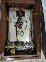
The sound from the right channel of my Sherwood SEL-400 amp dropped out suddenly and had a "hissy" fit, no smoke but I did smell something cooking when I opened up the amp and noticed that a very faint smell seemed to come from the Right channel output transistors.

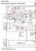
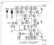
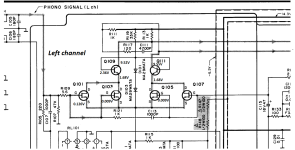
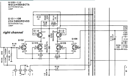
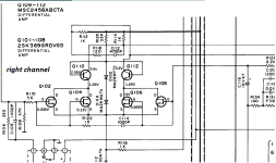
The schematic indicates that output the transistors are SJ1936 & SJ1937, these are present in the Left Channel and they each have a "blue dot".

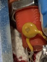
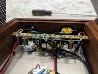
The Right Channel has Motorola SJ1902 & Texas Instrument SJ1903 which are obviously replacements so the amp must have had this problem before.

I pulled the outputs to test them and this is what the PEAK Atlas showed. (Three of them read what is indicated with an asterik*, the fourth does not). My guess is that the Right Channel transistor Texas Instrument SJ1903 is faulty since it is the odd man out. Can someone please confirm this?

Right Channel:

Motorola SJ1902


NPN Darlington Transistor
*Diode Protection between C-E
*Resistor Shunt between B-E
*hfe not accurate due to B-E res
Current gain hfe=27
Test Current Ic=2.50mA
Base-Emitter V Vbe=0.860V
Test Current Ib=4.096mA
Leakage Current Ic=0.000mA

Texas Instrument SJ1903

PNP Darlington Transistor
Current gain hfe=34
Test Current Ic=2.50mA
Base-Emitter V Vbe=1.172V
Test Current Ib=3.785mA
Leakage Current Ic=0.000mA


Left Channel:

Motorola SJ1936


NPN Darlington Transistor
*Diode Protection between C-E
*Resistor Shunt between B-E
*hfe not accurate due to B-E res
Current gain hfe=22
Test Current Ic=2.50mA
Base-Emitter V Vbe=0.807V
Test Current Ib=4.148mA
Leakage Current Ic=0.000mA

Motorola SJ1937

PNP Darlington Transistor
*Diode Protection between C-E
*Resistor Shunt between B-E
*hfe not accurate due to B-E res
Current gain hfe=23
Test Current Ic=2.50mA
Base-Emitter V Vbe=0.841V
Test Current Ib=4.113mA
Leakage Current Ic=0.000mA

Mid-Bass TL

Hi diyers,
I would like to submit this project for a mid-bass transmission line to you. I kindly ask for your help in identifying any errors or improvements.
The desired result was approximately 40-500hz bandwidth and the woofer selected was the Volt RV3143.
I tried to model the line with the Hornresp SW, these are the parameters used:
  • TL section: 800cm^2
  • TL length: 203cm
  • speaker offset: 60cm
  • section filling: 60% short part, 10% long part
The only way I found to replicate the upward extension declared in the speaker graph was to "cheat" on the Le parameter, lowering it quite a bit, but maybe I did something stupid.
I attach some screenshots, and thanks in advance for any help.

Attachments

  • Screenshot 2024-04-09 alle 17.27.11.png
    Screenshot 2024-04-09 alle 17.27.11.png
    49 KB · Views: 106
  • Screenshot 2024-04-09 alle 17.23.52.png
    Screenshot 2024-04-09 alle 17.23.52.png
    71.5 KB · Views: 103
  • Screenshot 2024-04-09 alle 17.23.25.png
    Screenshot 2024-04-09 alle 17.23.25.png
    70.4 KB · Views: 108

Useful infrasonic extension? How low do you go?

What do you think what's a useful infrasonic extension for home theatre? I loved chasing single digit extension but I'm not so sure anymore.

I had the Bag End Infrasub18 that played 8Hz. It sounded nice although only at very low levels.
I built a dual RCF LF18N405 450L ported subwoofer tuned @15hz in my hobby room. This one still puts a smile on my face when played at higher levels.

The problem is this though:

I built a dual B&C 21SW152-8 540L ported subwoofer tuned @11Hz in my living room and I also have a quad Visaton 15" TIW400 sealed subwoofer in there. I did some measurements and the sealed sub quickly drops off under 30Hz. Both ported subs also have a gap between their tuning frequency and the first room mode and I feel that both subs together fall a bit short around 20Hz without EQ. Also the movies with 10Hz content are rare.

I'm thinking of raising the port tuning of the B&C to 15Hz and also rebuild the sealed sub into a ported one also tuned at 15Hz. This way GD only starts to rise under 20Hz so music still sounds tight? The (still low) tuning frequency will also prevent the woofers from over-excursion below tuning?

Your thoughts?

Mark Levinson 33HH opamp upgrade

Hi friends
I need your help regarding upgrading my opamps in my mark levinson 33H
All the modifications that I have made to those amps gives them a new life and the sound became more analog.

However my question is divided for 2 parts:

1. The first part since those 33H has few revisions the earliest version uses AD705 and later version uses OPA277P
I have contact Harman group and they say that instead of the AD705 they use LT1097
I have compere the specs of the OPA277P vs LT1097 and I see any reason why to use LT1097 since the OPA277P is better by all means.
Did I miss something???

2. The second question related to the oscillator board of this amp
Since this amp has an AC regenerator for the input stage.
The oscillator uses NE555N and this connected to a series 3 opamps AD712JN
I was thinking to upgrading those opamps
To an opamps that have better specs of noise rejection to have better cleaner AC
Instead of the AD712JN I saw 2 options
OPA2134
OPA1642
The 1642 has better specs and is much faster than the 2134 and I'm afraid of oscillating problems.
Since I'm not expert in electronics
Please help me to to decide what to do in this case
I'm looking for direct replacement
If you think of better opamps and more suitable please let me know
God bless you all
Thank you

Only one channel with optical/coax connections?

Perhaps I originally posted this question in the wrong forum since I have received no replies. Yamaha receiver, RX V3000, no audio from left channel when using digital/optical input. Analog/RCA inputs work as they should, provide sound from both channels. Different digital cables give the same result. Input is set properly. Burr Brown DACs, 1704. Do these tank over time or could there be another issue? Where do I begin to trouble shoot? I have compared multimeter readings from one good identical Yamaha DSP board to the one in question, and all appears to be consistent. I am stumped. Any ideas?

IMF woofers GT 03

Hi
I've got 2 IMF, 3021 GT 03, I think they were made by Elac, woofers, used in the TL Range, they are in good condition, can provide DAT v3 data.
I used them for a while in a diy tl speaker, but decided to build a new set up, so no longer needed.
Price 125 Euro each, when bought together, total 225 Euro, shipping must be payed by buyer.
Cheers, Tom.

Attachments

  • IMG-20240418-WA0000.jpeg
    IMG-20240418-WA0000.jpeg
    224.3 KB · Views: 78

Bass preamp using flyback 9v - 300v PSU

This is a bass preamp , basically cloning a Gallien-Krueger Fusion 500 tone section . It has a 300 volt B+ feeding two 12ax7s driving active Lo-Mid , Hi-Mid , Bass and Treble controls. The power supply is one I developed from a flash-gun circuit I found online and a little 18mm flyback transformer from an old flashgun along with a 2sc4834 transistor , two polarised caps and a resistor and a couple of diodes. The 2sc4834 was chosen because it seems to have a high power-handling capability , so would be less likely to overheat , I don't know enough about transistors to make a more knowledgeable pick. For so simple a setup it performs remarkably well , I have a voltage regulator taking the 9v wall-wart input down to 6.3 volts and that feeds the heaters and the psu. I used an LD1085 regulator but it does seem to heat up more than others I have used so I would change it next time. The transformer is wound to produce 300 -odd volts from 6v battery supply in the flashgun , so with 6.3v it produces around 320 volts , I had to put a dropping resistor in . (I suspect it could go quite a bit higher if needed) . The voltage on the plates is about 202 v which is close to the G-K schematic. There's no sag I can see or hear , and the waveform of the AC ouput looks reasonable to one who knows very little about these things , the DC doesn't have a measurable ripple on my little handheld oscilloscope , but I'm new to all this and someone with better knowledge and equipment would be better placed to know if that was so. The preamp is quiet , on a frequency analyser the only sign of the switching power is a very tiny peak , mostly below -110db , which comes and goes for reasons I haven't found yet , I think it's probably emitted radiation from the transformer and I've done some shielding but perhaps it needs better. The peak and the switching is at 11kHz , which is far enough above the range of a bass guitar to not interfere , and at least to my ears there is no distortion anywhere (old ears , mind you).
The main problem with making and improving this psu is the fact that most of the flashguns I have taken apart to get more transformers use either smaller ones in the more modern versions and larger ones in the really old style. It seems that with this particular circuit the sweet spot for transformer size is around 18-20mm , to get a high enough frequency and a steady current supply. I have bumped the frequency up towards 20khz but got much more heat than I was happy with from the transistor, and above that it gets very jumpy. (I thought about winding my own and twice sent off for ferrite cores and bobbins from China , both times just got a load of broken ferrite bits in a bag with no bubble-wrap or anything to protect them.) I keep foraging them when I see a job-lot of old guns on the Bay , and one day I'll find which ones have the right size.
The circuit is minimal to say the least , it's possible that someone with more understanding could create a more sophisticated one that could utilize the more easily found smaller transformers , perhaps switching at a higher frequency. And I have learned that if there is noise , there are ways of implementing snubbers before the transformer , but they require pretty complex maths and knowledge of the transformer specs I think.
I had another valve in there at one point , another 12ax7 as an overdrive valve , and it worked fine , but the voltage regulator started to get more than a bit hot supplying the extra heater current so I took it out - I wasn't aware of the transformer having issues with the extra power however.
The resistor size depends on the inductance of the transformer and the target frequency. The multimeter resistance of the windings is about 0.5 ohms for the input winding and the flyback winding , and varies between 150ohms and 350ohms for the output HV winding on different transformers.
In the pictures the psu is crammed into a yellow box at the end , that's because the initial project was "Can I get a valve preamp into a Coleman's Mustard tin?".. the answer was "No" but the psu fitted into the lid OK.
The first frequency trace is with the bass pugged in, no sound, the second with a string plucked and the peak showing bottom right . It appears for maybe twenty seconds then disappears for a few minutes , there's no audilble change to my ears.
The controls on the preamp are : top , bypass switch and Volume control -: front , 3 way switch to alter the bypass cap on the first triode , (no bypass/10uf/ resistor and small cap.) , switch to add "Deep" to low-mid control , Hi-Mid , Low-Mid , Bass , Treble , input and output jacks.

Screen Shot 2024-04-16 at 20.26.06.png
2024-04-17 18.41.42.png
Screen Shot 2024-04-17 at 12.42.22.pngScreen Shot 2024-04-16 at 22.53.27.pngPsu.pngScreen Shot 2024-04-16 at 22.52.37.pngScreen Shot 2024-04-16 at 10.42.34.pngScreen Shot 2024-04-16 at 10.43.17.png

Attachments

  • 2024-04-17 18.41.42.png
    2024-04-17 18.41.42.png
    9.6 KB · Views: 106

Apogee Scintilla - A Project!

LOCAL PICKUP ONLY. NO EXCEPTIONS. Costa Mesa, CA

I have a pair of what appear to be 4 Ohm Apogee Scintillas that are in need of full restoration. My goal here was to follow in AVWERK's footsteps and make this a fun DIY project. I just don't have the time.

I have the following:

1. Pair of beat up Scintillas. They were stored outside by previous owner, they will need full disassembly, cleaning, probably new wood just about everywhere. Crossovers, stands, terminal plates, everything included. Removable covers have warping from water damage. They used to smell like cigarette smoke as well but I've had them in my garage for over a year now and I think that is mostly gone. All ribbons damaged. They stand vertical and look good from afar 😉

2. Roll of wide kapton tape (this wasn't cheap. Sourced on eBay from international seller). 0.025mm x 500MM x 33meters Amber Polyimide Kapton Film With Adhesive Single Side

3. Roll of foil (from Grainger) : Aluminum Foil Roll: 1100, 18 in Overall Wd, 50 ft Roll Lg, 0.001 in Thick, Mill, Full Hard

4. Parts to build corrugation device per AVWERK. This was tough to source, got it from a 4x4 truck parts shop.

The rest is up to you. AVWERK has a great thread in the exotic speaker forum here you can try to follow along.

Asking $1,500 for everything. Must come collect. Just want to recoup my costs. If you're up for a fun project the sky is the limit here 🙂

Please do not do the following:
1. Send me a message to kick the tires.
2. Send me a message to ask about how to go about the project. This is a DIY effort, do your own research
3. Send me a message asking if they are available - I will update this post when they are gone.
4. No pictures - don't ask.

I feel for the price this is a win-win. Price is firm - cash only.

Custom hand crafted Tube integrated Amplifiers

Hello '
I custom hand build single and push pull types of Tube preamplifiers to Intigrated Amplifier's with output tubes ,using El34, KT120, El84 for push pull types out put wattage rated at 10 to 275 watts RMS. And 211 ,845 for the single ended Intigrated amplifier s preamp stages using 12AX7, 12AT7,12AU7 , E188cc types the electronic components are sourced from the best brands all point to point soldering and some with tag pcb soldering.you could email me ' or WhatsApp me on +94777145436

The CAB is your worst enemy! (love it or hate it)

Put it to test how good or bad your expensive speakers are , around 05:00min :

Login to view embedded media (video in german sorry but you can switch to english in the settings , a bit tricky but works!)

Of course how strong the reaction of your speakers are , depends largely on the music you are using for this test! Use the normal playback level or somewhat higher to get a realistic impression of the unwanted noise that disturbs your high fidelity ambitions!

Easy to be done , takes no additional stuff , just some curiousity what's going on in your sound field during listening?

Why hasn't it be done as a standard test way back in history?

My suspicion is - most people fear to know how bad their speakers really are!

No excuse no more - kill all those sound devils that deceives you and take all your money , burning it in hell to torture those sinners down there 🙂

regards - death to all bad cabs 🙂

ps .. using pink noise for testing makes more sense and can be analysed to get a FR graph ...

Attempting to make sense of the HA1452W IC in my vintage Hitachi HCA-6500 preamp

I've had this 1979 amp and preamp pair for several years now, and I've often wondered if i can replace the near prehistoric "stereo preamplifier" ic with a modern opamp.

It sure looks to me like a dual opamp with external compensation and offset zeroing, but the datasheet is less detailed than we expect these days. For example, it says it has a differential amplifier, and does not specify which input is inverting or noninverting.

I've attempted to draw a simplified schematic, using an ne5534 as a stand-in for 1/2 of the ha1452w, and without the rest of the preamplifier input (a jfet pair) or the tone controls, etc.

Does this make sense to anyone?

I attempted to air-wire an adapter to an njm2068L but this just results in a hum at the output.
hca-guess (2).JPG
image-005.jpg

Attachments

Airplay and Android receiver suggestions

Currently fitting some ceiling speakers in my kitchen running to a TPA3118 based amplifier - all good on that side.

What I need is a receiver/device of some sort that will appear as a "Speaker" on an Apple device/Apple Music (so supports Airplay) and can stream from an Android from - generally from Spotify.

I could go down the Bluetooth route but I'd rather not as it would be good not to have to be a close distance to the receiver all the time.

I've got the hardware to setup an RPi Volumio install (Pi + DAC) (or PC + USB DAC) but that felt a little like overkill for this application.
Doesn't need to be Audiophile standard as the setup as a whole isn't.

Some devices I've seen - are they actually any good? Or a waste of money?

Audiocast M5
Wireless Receiver WR320
Arylic S10
IEAST Audiocast Pro M50

Needs to be a "Just Works" solution with good WAF.

Amplifier for Earphones? (in ears monitor)

Hi! first, english is not my main language, im a complete noob in electronics, i realy like to build mi own in ear earphones amplifier, here is my problem:

3.5mm out from a multifx processor (nux mg30) guitar pedalboard --> to a "custom" earphone (only one earphone "speaker", i recycled only one earphone from a bluethoot set and wired it to a 3.5 mm stereo jack (but it's only 1 earphone so it could be mono)

PROBLEM: master output from multifx controls both volumes: guitar outuput and earphone level.
i need independant earphone volume control, i built a passive one (it's basically a 10k logaritmic pot), but it doen't have enough volume at maximum level, i think i need an active volume control for this (an amplifier)

what's the easy and cheap way out of this? what can i build??
i've read multiple threads here, but i dont seem to find what i need since everyone is talking about "HEADphones" not earphones, i think this may be a major difference

Sin título.png

[For Sale] Stunning Live Edge Open Baffle Loudspeakers

As seen at BAF 2022!

Amazing one-of-a-kind live edge dipole loudspeaker pair made from solid slabs of Maple. Hand-crafted (by me) in the San Francisco Bay Area.

These speakers have a huge soundstage, great imaging, and high degree of overall realism. Few speakers outperform these.

This is a bargain: I am selling these at less than the material cost in order to fund (and make room for) further developments. Honestly, these are one of the best speakers I have ever made and will be sad to see them go. Unfortunately, the Eton Arcosia drivers have become difficult to source so I no longer make these.

I consider these demo/prototype units. There are some imperfections in the finish, but that adds to the rustic look. From the listening position, these are stunning to look at and hear.

Come audition in the SF Bay Area, California. Due to their size, I would prefer to sell locally. Shipping would need to be freight at the buyer's expense.

Message me on DIYAudio or buy on US Audiomart: https://www.usaudiomart.com/details...-baffle-loudspeakers-pair-demoprototype-unit/

Details: http://natursound.com/spirit.html

spirit_build.jpg

Attachments

  • spirit_details_1.jpg
    spirit_details_1.jpg
    575.8 KB · Views: 98
  • spirit_details_2.jpg
    spirit_details_2.jpg
    625.3 KB · Views: 89
  • spirit_details_3.jpg
    spirit_details_3.jpg
    392.4 KB · Views: 101
  • spiritbg_1934x1934.jpg
    spiritbg_1934x1934.jpg
    866.7 KB · Views: 90

Dual primaries to 230V: the dot

Up to now, I always had single primary power transformer, thus I am a little discomorted.

Here’s this little xformer, dual primaries, where the dots are on the outer pins.

To make it a 230V transformer, I bridge the outer Pin (dot) with the inner pin (no dot) of the other primary, correct?

Is there a method to measure/test it without connecting it?

Thank you all!

Attachments

  • IMG_6185.jpeg
    IMG_6185.jpeg
    428.4 KB · Views: 125

R-110SW / R-112SW / R-115SW Repair Blog

Hello All

I have been repairing Klipsch subwoofer amps for about 15 years as a hobby. I have decided to start blogging my repairs and eventually do videos of each one. This thread is intended to be a blog and a resource for information. I will try to answer repair questions as best I can. Comments and tips are also welcome, If you do not have the experience or the tools, PLEASE do not attempt any of these repairs. You will only end up damaging the board and it will end up costing more for a tech to repair the damage. If you do not have a high quality vacuum desoldering station (Hakko or Weller) and a current limited mains supply, you should not be working on these amps. These subwoofers do not have any user serviceable parts inside. If you open up the sub or attempt any repair you see in this thread, you are doing so at your own risk!!!


The main issue that I see with these is a thermal failure. The parts were placed too close together and since almost everyone is too lazy to switch them off when not using them the capacitors just cook and then things start to burn up.


ALWAYS REMEMBER TO UNPLUG OR SWITCH OFF YOUR AMPS. CAPACITORS HAVE A LIFESPAN AND WHEN POWER IS APPLIED THE CLOCK IS TICKING. THE AUTO ON/OFF FUNCTION DOES NOT PREVENT THIS ON MOST MODELS!!!!!!!

Line Pre-amp RCA and XLR

Bonjour à tous,

Je vous propose pour analyse ce préamplificateur de ligne, construit avec AOP OPA1611.
L’entrée XLR a un gain de 1, l’entrée RCA a un gain de 2 pour éviter d’avoir une différence de volume lors du passage de RCA <=> XLR.
Les deux interrupteurs sont en fait des relais. Je vais ajouter un relais pour commuter les masses, ce n’est pas sur le schéma.
Puis un potentiomètre de volume 10k et un buffer OAP.
La résistance R21 simule la charge.

Qu’en penses-tu?

Merci pour vos critiques constructives.

Alain

Pre-amp.png

Tannoy autograph mini active monitor cabinet, crossover, HF and LF amp build

I am looking at getting some Tannoy Autograph Mini drivers for £250 and want to build or buy and reuse some good sounding cabinets, crossovers that filter the original signal at 2.3khz, a low frequency and a high frequency amp.

I need suggestions on where to get suitable cabinets or designs to build; crossovers, HF amp and LF amps or recommendations on where to get them as either kits or pre-builtI. I am looking for suggestions and opinions.

Thanks,
Philip

Marantz 7 preamp inspired clone issues

Hi,

I am building a Chinese kit for a friend, I have no experience with tubes or audio so this is quite challenging to debug.
This is almost the same kit that my friend got

https://www.fyfaudio.com/products/h...amplifier-marantz-m7-circuit?VariantsId=10237

The wiring diagram is not very clear but I managed to understand the connections, it doesn't work, the output volume is very low.

1713321801564.png


I measured all the voltages (top caps and pin 1,6, 3 and 8 of tubes) and are within a 10% range of the values of the schematic above, what would you think is wrong?
it seems that is rated 30W, I am using a 6ohm 10W speakers, audio is very low, doesn't sound distorted to me
Thanks

The Genus Behind Wide Baffles

Hello all,

Recently I have taken an interest in studying diffraction's effects on loudspeaker response, after reviewing Gedlee's whitepapers. Gedlee's research shows that linear distortion artifacts of diffraction are highly audible, more so than non-linear distortion. On the full-range thread I studied the correlation between full range polar response in relation to speaker diameter. This was an effort to use driver beaming to reduce the frequency bandwidth effected by diffraction loss. In summary, you can not practically eliminate all diffraction related distortions by using high directivity fullrange drivers on maximally small baffles. ...but what about creating a speaker that effectively has no baffle step, because the baffle is so large that it loads all frequencies equally?

I've recently taken interest in the design behind Stereophile's A rated Devore Fidelity Orangutan O/96. It's a pretty unusual speaker in that it uses a wide baffle, against the current grain of "tall and skinny" loudspeaker design. Going over reviews on the internet, I came across an interesting tidbit behind the engineering of the O/96. John DeVore states,

"... It eliminates what a lot of people call the step response. Which is where the speaker goes from broadcasting its sound[wave] forward in a hemisphere because the baffle has a certain width, to broadcasting into the room as a sphere because the sound wave becomes double the width of the front baffle, and generally speaking, at that point, whatever frequency that is, the power response in the room will drop...

Hide the fact that there is a baffle by moving the speaker close to a wall boundary so that the wall boundary essentially catches what’s left and everything is coming forward in a hemisphere no matter what the frequency. The other way to do it is to move the frequency so that the step response happens by changing the dimensions of the front baffle, and that’s what we did with the ’96."


Some simple math can show exactly what he is talking about here.

g-phy-prowav-dia04c.gif


"When a loudspeaker produces a sound, this sound is in the form of a pressure wave trying to expand equally in all directions spherically (like the balloon analogy). The first obstacle that this wave encounters is the baffle face itself. For higher frequencies with shorter wavelengths where the baffle is acoustically large, the baffle causes a doubling of axial pressure into the forward hemisphere (since the pressure can’t expand spherically), much like a perfect reflector. This doubling of acoustic pressure produces a +6dB gain on axis in the forward hemisphere. A baffle with a width of about 9” would correspond to one wavelength at about 1500Hz, this +6dB gain would then be seen at frequencies above 750Hz (that half-wavelength rule)." - Salk Sound

The O/96 utilizes a 18" baffle. 18" would create a baffle step at 376Hz. The wavelength of 376Hz is exactly 3 feet.

Thus, if a speaker with an 18" baffle was 3 feet or closer to the wall behind the speaker, the baffle will appear acoustically infinite - no baffle step. 😱 \

Tube AC heaters on PCB

I am designing a PCB for a tube compressor with a max gain of about 40dB

The heater supply requirements is 6.3V 1.6A. Initially I thought to make it DC regulated, but the power transformer gets too big for the chassis I'm using.

I am wondering if there is a way to run the AC heaters on the PCB without causing too much noise.

Perhaps running the connections on the edge of the pcb away from grid circuits would be safe enough, or maybe some kind of heater elevation would help ?

I am seeing a few diy projects that run the heaters with the classic twisted pair off board but I am also seeing commercial units that seemingly run the heaters AC on the PCB. So I guess in some way it's possible.

Wondering if someone has any experience with this.

Rega R200 12" conversion - uses SME 12" geometry stainless steel arm tube

Selling my 12" Rega R200 special.

This uses a nice custom made heavyweight SS tube with SME3012 geometry.

Custom armbase for adjustable VTA.
Extra heavy SS counterweight.

Fitted out with Cardas din standard phono connector.

Rewired with Litz silver tonearm wire.

(No Rega anti-skate function - not required for 12" arm)

Suits low compliance cartridges.

£170 plus postage, or collect free (UK based)

Attachments

  • IMG_5393.JPG
    IMG_5393.JPG
    532.9 KB · Views: 63
  • IMG_5394.JPG
    IMG_5394.JPG
    316 KB · Views: 66
  • IMG_5396.JPG
    IMG_5396.JPG
    371.4 KB · Views: 63
  • IMG_5397.JPG
    IMG_5397.JPG
    242.5 KB · Views: 74
  • IMG_5400.JPG
    IMG_5400.JPG
    389.2 KB · Views: 68
  • Screenshot_20240417_160944_com.google.android.apps.docs~2.jpg
    Screenshot_20240417_160944_com.google.android.apps.docs~2.jpg
    129.6 KB · Views: 68
  • Screenshot_20240417_160955_com.google.android.apps.docs~2.jpg
    Screenshot_20240417_160955_com.google.android.apps.docs~2.jpg
    87.4 KB · Views: 63

Cyburgs-Needle for Tangband W3-871S

I hope that this could be of interest for you.

I constructed the Cyburgs-Needle originally for Visaton FRS8, which is a nice and cheap fullrange driver here in Europe. The Needle was quite a sucess here, I know of about 20 pairs built by DIYers, and there may be even more. However, I have been looking for an alternative driver to make a "High-End" version of the Needle. I tested several different 8cm drivers, and the Tangband W3-871S finally did it. Unlike the FRS8, you need a notch filter, the values you will find in the plan.
I think that the availability of the Tangband is better outside of Europe, so I hope you will have fun with this plan.

Nice greetings, Berndt

An externally hosted image should be here but it was not working when we last tested it.

For Sale Waynes Preamp with Muses Volume Control in 1U Chassis

I built this preamp to experiment with Academy Audio's Muses control and I loved it so much I built a bigger one with their BIB and BOB with the Waynes board.

I am selling this one as it is not getting any use and I need to fund some other projects. Below is a rundown of the parts I used:

  • Galaxy 1U silver chassis with 4mm faceplate
  • Academy Audio LPS9 regulator
  • Academy Audio VCX (older model)
  • Waynes Preamp with quality precision resistors
  • Blue illuminated vandall push button switch.

Unit has two inputs, two rca outputs, Headphone switching jack, the remote, and runs off a 5V Meanwell Wall Wart recommended by Academy Audio.

I am asking $350 and I will ship it for free anywhere to the continental US.

For Sale Pass F4 Amp in 4u 300m chassis with Soft start and Pass FE boards

Selling one of my F4 amps. I have two other f4’s I use as monoblocks so no longer need this one.

Amp details:
  • deluxe 4U 300m iron chassis, black faceplate
  • Mark Johnson’s soft start with push button switch
  • Pass Front End boards
  • switches for RCA or XLR input.
  • silver coated wiring and metal foil speaker output wire
  • genuine matched Toshiba JFets and matched Mosfets from Diyaudio store

Asking $900 and I’ll ship for free anywhere in the continental US.

Picture shows amp under a Wayne’s Preamp and Pearl 2. The Wayne’s is still for sale but the Pearl 2 no longer is available.

Attachments

  • IMG_4923.jpeg
    IMG_4923.jpeg
    621 KB · Views: 245
  • IMG_4922.jpeg
    IMG_4922.jpeg
    595.8 KB · Views: 238
  • IMG_4921.jpeg
    IMG_4921.jpeg
    669.3 KB · Views: 244
  • IMG_5700.jpeg
    IMG_5700.jpeg
    518.2 KB · Views: 247

International Guitar Month and Innovation Day April 21 in Charlotte NC - Featuring SiC Jfet Guitar Amps

This is for anybody that is in Charlotte, NC and is interested ..

Experience the Revolution in Guitar Sound at the North Carolina Science Festival!
Showcasing SiC Jfet Event with Dr. Mike Mazzola and Dr. Jim Gafford!

Dr Mike Mazzola was the chief technology officer of Semisouth Laboratories when they developed the Static Induction Transistor(SIT) for Nelson Pass at First Watt. Dr Jim Gafford is an Electrical Engineer professor at UNC Charlotte and has developed SiC Jfet to work in Vacuum tube applications.

Join us at Discovery Place Science, located at 168 W 6th St, Charlotte, NC 28202, on April 21, 2024, from 11 AM to 4 PM for a groundbreaking showcase where tradition meets innovation in the world of electric guitar amplifiers. Dr. Jim Gafford and Dr. Mike Mazzola, along with unveils a pioneering transistor that mirrors the beloved qualities of the classic vacuum tube. This exclusive event offers you the rare opportunity to play and compare guitars equipped with traditional tubes and the revolutionary SiC Jfets.
Mark Your Calendars for April 21, 2024, from 11 AM to 4 PM! Dive into the future of guitar sound, explore the crisp, warm tones of the SiC Jfets, and see how they stack up against the classic tube amps. Whether you're a professional musician, a hobbyist, or simply a fan of great sound, this is an event you don't want to miss at the North Carolina Science Festival!
Come Hear the Difference - Feel the Revolution in Sound at Discovery Place Science!

Discovery Place Science
NC SCIFEST

SiCJfet.jpg

Elimination of Grid Stopper Resistors and Weird Behavior between Preamp and Amp

Ok, in the pursuit of a "less-colored" signal path I realized I could remove the grid stopper resistor between my DAC and my preamp as shown on the left side of the diagram below. This made a huge improvement and have had no issues after doing this. When I eliminate the 3k grid stopper resistor between my preamp and amp though, I get weird hums/buzzes/cable noise and all kinds of other weird behavior and get varying levels of hum from lots to none based on cable proximity and position (very werid). If I do put the 3k grid stopper resistor in on the amp these issues go away but the problem is that it sounds SO much better without the grid stopper resistor. I have tried several different resistor types (Audio Note tantalum and Naked Vishay) and it always sounds better without it.

I have two questions:
  • Why is the grid stopper needed between the pre-amp and amp and NOT in between my DAC and the preamp? What is different? Is it the output impedance to shunt resistor relationship? There is also a 1M rca cable of the same type between the DAC and preamp.
  • Would changing the value of the 1M shunt resistor on the amp solve the hum/noise/strangeness problems and allow me not to use a grid stopper resistor?

Huge thanks,
Brett
RCA Question.png

Overview of Brands and Models from first Solid State Audio Amplifier Components want

Here already are two threads regarded similar subjects concerning newer generations of solid state devices:
1) a. http://www.diyaudio.com/forums/soli...-models-quasi-complementary-power-output.html
1) b. http://www.diyaudio.com/forums/solid-state/162142-tip3055-2n3055-based-power-amps-3.html
2) http://www.diyaudio.com/forums/soli...st-complementary-ab-bipolar-amplifiers-5.html

But now I want to know the first generation high quality solid state comercial audio devices (radios, car-radios, home receivers, preamps, integrated amps and power amps for home-audio, studio/stage/instrumental-monitoring and public address) - independend, whether there is OTL or not so as complementary output stages or not.
Therefore I have create a URL collection about a wide range of "First Generation" transistor types - mainly from central Europe, USA and Japan. A wide range of photos you will find here.
With help of this it is more easy to discover the first model numbers and brands from audio devices in the aera between 1955 - 1965. But please note - because in the transition time most audio devices are a long time still equipped with tubes, at least here in Germany, there are not a wide range of solid state amplifier components.
If anybody is owner of a collection of the magazine mentioned there
http://www.diyaudio.com/forums/soli...sen-jikken-yearly-index-1924-2009-wanted.html
it is easy to find out some models and brands from that aera.
Thank you very much for your advices.

Basic Informations about History and Theory of Operation

First-Hand:Beginning of the Silicon Age - GHN
www.vintagetransistors.com
PNP-Transistor

NKT (newmarket) series
Mister Transistor's Historic Semiconductors

Power Devices from GDR
KHB-Radios -
KHB-Radios -

Collections of various Vintage "first Generation" Types, mostly Germanium, low and medium power devices:

Transistor History (Transistor History)
Raytheon Part Two (Transistor History)
USA Transistors (Transistor History)
Philips (Transistor History)
History of AWV (Transistor History)
http://groups.google.com/group/ham_radio_bulletin/web/oude-onderdelen-onder-de-microscoop?version=5
Germanium-Transistoren und -Dioden
Wumpus. Transistors
Wumpus. Transistors
Vintage Transistors & Diodes
Brand History (short form)
Transistor Museum Early Germanium Power Transistor History by Joe Knight Clevite Transistor Products
Transistor Museum Construction Projects Point Contact Germanium Western Electric Vintage Historic Semiconductors Photos Alloy Junction Oral History
Transistor Museum Photo Gallery Motorola Germanium Power Transistor Prototype
Transistor Museum Photo Gallery Raytheon CK705 Historic Germanium Diode
Transistor Museum Early Germanium Power Transistor History by Joe Knight TI Page 5
Transistor Museum Photo Gallery Raytheon CK793 Silicon Alloy Junction
Transistor Museum Photo Gallery CBS 2N155 Germanium Alloy Junction Power Transistor
ABQ-Techzonics Transistors - Bipolar MOSFET,FET,IGBT (Gallery - for vintage part scroll down)

Collection for use by Telefone
Transistor

Transistor History 101 by Bob McGarrah

Transistor History 101

Raytheon first transistors designd by Mr. Frank Dukat

next

THE CK722 CLASSIC GERMANIUM TRANSISTOR MUSEUM
CK722 Classic Germanium Transistor Website and Museum Photo Gallery Photograph Page6

EARLY TRANSISTOR HISTORY AT RCA

RCA Transistor Oral History Kalish Index
50 YEARS of the CK722
CK722 Germanium Transistor Construction Projects New Volume Index

First Generation of Japan Transistors:

Hitachi Transistor
TransistorArchive: ???????????????? ?????
TransistorArchive: ????FUJITSU ?????
TransistorArchive: ???TOSHIBA ?????
TransistorArchive: ????SONY ?????
TransistorArchive: ???SANYO ?????
TransistorArchive: ???MATSUSHITA ?????
TransistorArchive: ???HITACHI ?????

TFK OC/OD Germanium Power Devices Series
telefunken
techinfo2

list of a wide range from vintage transistor data books
Hersteller und Quellen - Manufacturers and References

Overview and short form data of BjT Germanium power devices

Bipolare Germanium-Leistungstransistoren - Bipolar Germanium Power Transistors
Grenzwerte von Germanium-Leistungstransistoren - Germanium Power Transistor Maximum Ratings
elektronische Bauelemente - Transistoren

Delivery Source - Ordering Address

Results for Semiconductors:Vintage
Atomic Mall - Related Items

Advices to additional Delivery Sources

Germaniumtransistoren, wo zu haben? - Mikrocontroller.net

First Examples of first generation Solid State Radios/Receiver, Integrated Amps and Power Amps
http://home.arcor.de/pfaue/klangkue/verstaerker/beo/beo900.htm
TR1 - Hardware-Fachbegriffe Online Lexikon (erstes TI-Taschenradio)
Drucker, Geräte von Dual, Röhrenradios Dual erster Transistorverst.
Mein eigenes Kolter-Museum
Transistorradio
Radios Antigos no Brasil
Vintage Radios Australia
Silicon Chip Online - Vintage Radio

Preventing Sansui AU-X1 output stage oscillation burn out

I've got this Sansui AU-X1 in the workshop in order to find a solution to prevent the issue with output stage oscillation, that had caused some AU-X1 to burn out the output stage.
I've been reading some threads on several fora e.g. audiogon etc. regarding this issue, and it seems like this issue is only present when no speakers/load is connected - even only a set of connected headphones should prevent this oscillation. I did not find any add-on/mod solutions though!
Then in a short "brain fart" it came to me, that if one build in a separate seudo headphone load (resistors, inductor and cap only), the problem should be solved. This would only put very little load on the output stage and would not affect the performance in any way......
What do you guys and girls think??
Thanks for any input to come 🙂

For Sale ICEpower AS1200 - 2 x 700watts.

I have for sale a ice power as 1200 as2 .The amplifier has original accessories and warranty.
I was bought on European store. Used on PS Audio Stellar M1200 - not cheap...
I asking 300€.. shipping registered on Europe included.
Is like new.

Attachments

  • IMG_20240414_194542.jpg
    IMG_20240414_194542.jpg
    321.8 KB · Views: 137
  • IMG20240414193449.jpg
    IMG20240414193449.jpg
    270.8 KB · Views: 129
  • IMG_20240414_194522.jpg
    IMG_20240414_194522.jpg
    291 KB · Views: 130

Gulbransen APS-5 power amp - ground-up rebuild

Subject amp was brought for next to nothing and it was gutted. All that was left was the chassis, the transformers, the tube sockets, and the heater wiring. I replaced the sockets and the heater wiring and I tried not-so-successfully to nickel-plate the bell ends of the transformers. From what I've been able to tell the amp was made circa 1960 and was part of a transistor-based organ (part of what was in this chassis was the power supply for the organ electronics; all of that's gone and the associated PT secondaries are blocked off and wrapped up).

Obligatory gut shot:

gut_shot_apr_11_2024.JPG


The schematic shows one component change (unobtainum; substituted 250 ohm 5W for 225 5W) and I've crossed off sections that were omitted. I crossed off the input/V1 stage because I changed enough to just redraw it; both are below:


jlh_modified_original_schematic.png


jlh_new_front_end_schematic.jpg


I simplified how that first segment of coax is drawn; the actual layout doesn't look like that. Rather, ground "emanates" (if you will) from the end of the preamp-side ground busbar to the low leg of the volume pot and is carried via coax shields from there towards both the input jack shield contact and toward the V1 grid(s) but note that the segment of coax from the volume pot to V1 is grounded only at the pot end - this was a late addition to address some audio-range feedback that was creeping in. Both input and speaker jacks are isolated from the chassis. The big changes in the front end are the paralleling of the two V1 triodes instead of leaving one unused, the values of V1's cathode resistor and bypass cap (I had intended to use a 10uF but didn't have one on hand), and the value of the V1 plate resistor (started with 56K; wound up with 47K). I tested putting a 4.7K resistor in front of the V1 grid(s) to reduce how much the function generator input signal was getting dragged down when the volume pot was turned up but it didn't seem to help much at all so I removed it.

The power tubes are new TAD 6L6GCM STR Redbase. The two 12AU7s and the 5U4GB are vintage; they were collected from the same source and are branded "Beckman" (electronic medical equipment manufacturer). All were tested on an Eico 667.

The two ground busbars meet and turn together toward the preexisting solder blob. The ground wire from the power cord and the PT center tap are soldered together with the two busbar ends into a thick column. There was a now-unused connector near one of the 6L6es with a terminal placed ideally for the far end of the power stage ground busbar to be soldered to in order to stabilize it; I chose to leave it like that.

It amplifies.

Power - By connecting the amp to an 8-ohm resistive dummy load with a scope across it and feeding a 1000Hz sinewave into the input, before the output clips I measure/calculate 18.6W going into the load ((Vrms^2/8). That's not the ~50W I was expecting. I have read here that it is possible to have a dual-6L6 amp in that power range in Class A but I'm not savvy enough to know if that is in fact how this amp was designed or if I have something else going on that's out of whack. I can say, however, that when I adjust my variac to get the 500V B+ as indicated on the schematic, all the other indicated voltages are very close to what I measure. It may be the case that the 250-for-225 substitution of the 6L6 cathode resistors wasn't a great idea; I could parallel a 1/2-watt 2.2K there to bring it to 224.5.

My intent was to recreate the APS-5 as opposed to put something else into an APS-5 chassis (after all, the transformers are for the original APS-5) so if it is in fact an 18-19W amp then so be it.

I've been doing some reading and my understanding is that what characterizes Class A operation is that the power tube plates are carrying a current which tracks the input signal throughout its entire excursion. I suppose I could put a small sampling resistor of sufficient power rating in series with a plate and throw a scope across it (while the amp is on an isolation transformer, of course) to determine if it's running as Class A; does that seem worthwhile?

Frequency Response - my -3dB knees are at 130Hz and 25kHz (!). I would have thought I would see a lower bottom end but I don't know what's typical for this sort of amp. It is not audibly lacking for bass running ordinary music program through a three-way loudspeaker.

Phase Response - If my input signal is around 10kHz, I've got something like 30 degrees of phase shift. Is that normal?


I welcome your insights and I thank you in advance.

Karlson's "X15" A New Frontier in the Perfect Size

(this is a segment of the upcoming "Karlson Compendium"

John Karlson and Wayne Green completed the famous "K15" prototype in the summer of 1951 and it was introduced commercially at the big names Hi Fi show in the Hotel New Yorker, Fall 1952.


K15 had a long run, produced in the thousands, but as time moved forward and the playback mediums of vinyl and tape heading away from mono to two channel, plus the acoustic suspension revolution of Edgar Vilchur and Henry Kloss, K15 was too cumbersome in pairs for small rooms.

Karlson with the 1964-65 World's Fair and K15 with Electro-Voice 15TRX supplying sound for a number of exhibits including Disney.

It was late 1965 when AUDIO Magazine's Annual Directory announced Karlson's X15 speaker. It featured a custom CTS woofer, much like a K33 but with less excursion and higher sensitivity. Also, the first model used a 3 inch cone speaker which fire into a custom Karlson asymmetric ("klam") lens. Subsequent models featured a slotted pipe with a one inch format compression driver made by University Sound. Two different diameter slotted pipe waveguide have been seen so Karlson was certainly experimenting Also, one X15 for organ use had a conventional horn in its front chamber, pointing up at a angle.

X15 with nominal dimensions of 28" tall, 20" wide and about 14" deep, had roughly a bulk of only 4.3 cubic feet - just one cubic foot larger than Karlson's 12 inch ("K12") model, and only about 57 percent the bulk of K15, so a stereo pair really could fit many rooms.

At ~57 percent bulk of K15, and fixed sensitivity 15 inch speaker, X15 would have its low frequency cutoff about a half octave higher than that of K15. Nonetheless, like a good K12 setup, percussion transient are impressive and cone excursion in the passband reduced vs a 12 inch speaker.

Also, X15 incorporated a 3 panel approximation of an ellipse curve upper reflector. (That was covered as an improvement in Karlson's 2nd and final "Acoustic Transducers patent,, #3540544).

Sometime around 1980, a number of X15 size K-coupler appeared on the market. I think Karlson's widow sold rights to at least 5 companies 😀 There was Transylvania Power Company, KK-Audio, Acoustic Control, Westwood, and a little company in Chicago, all producing pretty much the same cabinet.

With hindsight I wonder if these company's even knew there had been an X15 already with large port, pretty much what they ended up building and same with Cetec -Gauss when Karlson already had a "K18"

FWIW, I'd love to find someone who would make a nice pair of the wooden klam to try with say Faital Pro's 3FE22

Attachments

  • X15 THE NEW PERFECT SIZE.jpg
    X15 THE NEW PERFECT SIZE.jpg
    214.7 KB · Views: 1,342
  • X15 A NEW FRONTIER.jpg
    X15 A NEW FRONTIER.jpg
    203.3 KB · Views: 1,282
  • Audio-1965-08 PRODUCT PREVIEW KARLSON X15.pdf
    Audio-1965-08 PRODUCT PREVIEW KARLSON X15.pdf
    165.7 KB · Views: 205
  • X15 PORT SYSTEM.jpg
    X15 PORT SYSTEM.jpg
    47.6 KB · Views: 1,208
  • X15 BIG PORT DIMS.jpg
    X15 BIG PORT DIMS.jpg
    320.9 KB · Views: 1,174
  • KARLSON X15 LARGE PORT 3.jpg
    KARLSON X15 LARGE PORT 3.jpg
    75.8 KB · Views: 1,206
  • X15 WOOFER T-S.png
    X15 WOOFER T-S.png
    110.4 KB · Views: 570
  • X15 CLONE K-TUBE ASSEMBLY.jpg
    X15 CLONE K-TUBE ASSEMBLY.jpg
    190.6 KB · Views: 634
  • Karlson_X15A TB46 PLAN WEB.jpg
    Karlson_X15A TB46 PLAN WEB.jpg
    286.1 KB · Views: 716

Newly aquired Tube preamplifier - need opinions

Hello dears
I have recently aquired tube preamplifier from one of my friends, he claims that he got it from Singapore, i saw same design on ali excpress though. Anyway, pre is very nice, in very good shape, sounds amazing, however, i noticed small shhhhh sound when i put my ears next to speakers, this shhhh were audible on my solid state preamp before also, but was twice lower,

This preamp is pushing allot of power to my power amp were i need to raise volume only on 1 ( 8 o'clock ) , i will try attaching some videos and photos for the pre and willing to get your kind openions.

Tube pre (unnamed)
Power amp (krell kst 100)
Speakers ls50
https://photos.app.goo.gl/RxKK8sPHEoCdSdrY9

Thanks

Attachments

  • PXL_20240416_151828345.jpg
    PXL_20240416_151828345.jpg
    225.9 KB · Views: 139
  • PXL_20240414_162835510.MP.jpg
    PXL_20240414_162835510.MP.jpg
    303.8 KB · Views: 139
  • PXL_20240416_151451367.jpg
    PXL_20240416_151451367.jpg
    510.4 KB · Views: 143
  • PXL_20240416_151446228.jpg
    PXL_20240416_151446228.jpg
    522.4 KB · Views: 143
  • PXL_20240416_151500647.jpg
    PXL_20240416_151500647.jpg
    395.9 KB · Views: 138

NAIM Supernait Troubleshooting

Hello all,
I've been perusing the forum for years, however this is my first post.

I bought a Naim Supernait (version 1) on eBay a few years ago and it was not functioning properly. I missed the return timeline.

The issues- right channel has pretty significant buzz/hum.
Amp sometime automatically mutes (safe mode?)
One input plays, a few have no output and one (the Tuner) input through my main house breaker once. Yeah, the main one....
I've pop'ed the hood and nothing looks obviously damaged.
I have a meter but no scope or other audio repair equipment. I'm confident in replacing a cap or resistor if this forum can help me diagnosis, otherwise it's going to have to go back Naim for the $1k+ repair.

Thanks all

Building a 5V and 12V regulated power supply (using LT3045) with NiMH / Li Ion battery for DAC and 12V PreAmp

Hi, I am thinking to use this LT3045 board (LT3045 Dual Channel Positive Voltage DC Power Supply Low Noise High Precision Linear Stabilizer Upgrade DAC - AliExpress) to build regulated power supply with batteries.

Target usage:

5v DAC (powered by USB type C, 3W max) by using one LT3045 board with parallel output
12v Tube preamp (should be less than 1A) by using another LT3045 board with parallel output

Before go ahead, I would like to seek some advices here. I hope you can share your valuable advice as I am pretty new to DIY hifi stuffs. 🙂

Questions:

1. Does it make sense to you at all for the target usage?
2. Which battery type is better (i.e. having lower noise)? NiMH or Li ion?
3. Can NiMH provide enough current for LT3045?
4. For 5V output, what would be the ideal DC input voltage?
5. For 12V output, what would be the ideal DC input voltage?
6. Any linear regulaor that is bette than LT3045 for my target usages?

Thanks a lot for your advice.

Scanspeak 13M/8636 - sudden death

There are an old thread where another experience the 13M/8636 suddenly died, apparently without any cause. Here
I disassembled mine for a closer look.
Using a sharp surgery knife, I was able to carefully lift the rubber surrounds from the basket, and do the same with the spider.
The tricky part is to get the knife under the rubber/fabric without cutting.
When the rubber/fabric is lifted a bit, the rest comes off rather easily.

d9o3TCa.jpg

F5oVweD.jpg


Here's the one side wire going from the coil to the litze thread:
EbYeVXK.jpg


And the other side, where the wire from the coil reveals to be corroded (all black and swollen):
UYNBPtH.jpg


Removing a bit of glue to expose the wire itself revealed that the wire is simply falling apart when being touched,
Hqt4k2e.jpg


I decided to remove it all.
After carefully having removed the glue this is how it looks:
zhC8xld.jpg


Turned out that the wire was more or less corroded through the spider.
Scraped the lacquer off the piece of coil wire where it seems solid and soldered a replacement wire
TQlZTSM.jpg

GTMpCRj.jpg

The wire and solder points has been soaked in glue, similar to the un-damaged side.

Have tested the driver, having the rubber surround and spider hold in place using a bunch of clamps, and it seems to work just fine.
However, I still need to find some way of removing the old glue from the spider, before glue it again.
Any ideas?

Help Eurovox amplifier model: EV-A1000D does not have audio

The eurovox brand amplifier, model: EV-A1000D
This amplifier does not have audio. Check with the oscilloscope. I do not have a pulse train in the gate. Apparently the transistors Q110, Q111, Q112 were manipulated. I don't know if they are the correct license plates. If anyone had information about the amplifier or which pulses to check, I would appreciate it. much Greetings.

Attachments

  • DSC01295.JPG
    DSC01295.JPG
    609.4 KB · Views: 78

Project viability check - 12L vented 6.5" full range

Initial Goals

I am looking into getting/building a set of relatively small stand speakers to fill a room that is around 25square meters or 270 square feet.
The amplifier for this system is a Marantz 2216B giving around 16W into 8ohms.

I have found locally a pair of Yamaha HS7 monitors sold for parts. The amps are working, but the woofers are torn and the boxes have a few scratches (that I can live with). I am looking into options and deciding how much sense does it make to use these as a basis

The boxes are made out of 20mm MDF, and are 210x332x284mm giving ~12.8L (internal).

The woofer's center is 6.5" and the tweeter's is 1". And they have a port behind the tweeter that is tuned at 50Hz.

The woofer is at around 120mm from the bottom. The tweeter is at around 65mm from the top. Both speakers leave around 10mm from their own edge to the speaker's edge (end of tweeter waveguide and woofer plastic bezel)

Thoughts

1) I guess the simplest would be to get their own woofers (40 bucks a piece). The problem is that the 2216 does not have a pre out, so I would have to use the tape out and control volume through their own controls. Plus, the woofers are not really a well known quantity, and they do need some EQ to fix some issues. Plus, they are 4ohms, so more difficult to drive in case I decide to experiment with them any further.

Here is a link to detailed measurements
https://www.audiosciencereview.com/forum/index.php?threads/yamaha-hs7-review-studio-monitor.19761/

2) Get some other speakers to use with the integrated amps and active crossover. I understand that finding a complete match that sounds well is a long shot. And I would still have the same issue with the pre-out.

3) Get rid of the integrated amps and use some full range speaker in them , leaving the tweeter and some electronics in place to just fill the holes.

This probably makes the more sense. Especially since the monitor electronics are not really built for fidelity. I would still have to at least remove the limiter.

An issue with this would be that to fit a round woofer I would have to modify the tweeter's waveguide.

Using my mediocre experience with speakers, I was thinking perhaps something like the alpair 11MS that seems to work ok with even smaller boxes, or the Fostex FF 165 WK (the bass reflex boxes suggested are quite larger though). The fostex has the extra pro that it would fit without having to modify the tweeter.

Can you please suggest me some drivers that make sense for these boxes? Or maybe just call me an idiot and point me to the correct direction?

Thanks in advance

Calculating Transformer Fuse

Hello, i was wondering if i got things right,

assume we have 2 transformers in this configuration:

1x230V Primary
6x8V 5A Secondary

1x230V Primary
2x15V 5A Secondary

what would be the safest route to protect the whole device? i read some people just use a fuse on the primary but that doesnt make much sense... the 8V 5A secondary draws 40W max, so to protect the secondary effectivly i would need a (40/230=0.17) 0,17A primary fuse (?!) please enlighten me here

Calculating Rc and Re in a Common Emitter Amplifier circuit

I'm new to circuit design and trying to read and learn a lot, but almost every calculation for common emitter amp circuit components is slightly different. I understand that there are many variables in this circuit, but all these different methods just giving me more confusion.

What would be the right way to calculate Rc and Rc out of these:


Calculating the Collector Resistor (Rc):

Version 1: Rc = Vcquiescent / Icquiescent = (Vcc / 2) / (Ic / 2). So here we have a maximum collector current (Saturation). We want the quiescent current to be somewhere in the middle, halfway of Ic and use that to calculate Rc. This doesn't make much sense to me as in this case Icquiescent becomes Ic as the resistor will determine the maximum current as Icquiescent.

Version 2: Rc = Vcquiescent / Ic = (Vcc / 2) / Ic. Using maximum collector current. (Saturation)

Calculating the Emitter Resistor (Re):

Version 1: Re = Ve / Icquiescent = (Vcc / 10) / (Ic / 2). Using the quiescent collector current to calculate Re. Ve is chosen to be one tenth of Vcc. We also assume Ie is same as Ic.

Version 2: Re = Ve / Ic = (Vcc / 10) / Ic. In this case we use the maximum collector current available at saturation.

For Sale Pair of VT-62 / 801A tubes

[SOLD]

Up for sale a pair of VT-62 / 801A.

One is Hytron, clearly NOS because it still has an original customs sticker which typically fades quickly after a few hours of use. The other is RCA, looks NOS for what I can tell.

On my calibrated TV7-D/U, Hytron tests 67, and RCA tests 70. Threshold for good is 38.

I would sell them for 130 EUR (or 145 USD), shipping included. Returns accepted as long as they are received in the same electrical and cosmetic condition as they were sent.

Next lot I will be posting is a bunch of Telefunken RS237 and GE VT-4C.

Cheers
Ignacio

[SOLD]


IMG_0152.jpeg

new layout for LFA 50A

A few years ago I fully redid the layoutdesign for my elektuur lfa50a.
the componentplacement is about the same but there is more room voor biggercaps and foil c's. I also made a large board for the big powercaps. As you can see on the attachment. So there are almost no wires anymore. I think that looks very cool. And the best thing is its sounds really great too.

I have an 2sk389 as inputdifamp because 2sk146v was not avaliable anymore. And no inputcap. Because my preamp has outputcaps. But I can always put room for one on the layout if you want one.

Let me know, Roy

To me the lfa50a is a great amplifier

Attachments

  • lfoa50a.jpg
    lfoa50a.jpg
    91.4 KB · Views: 1,544

For Sale Gustard X20 DAC

$325 plus shipping from Las Vegas NV

Also have a KECES DA-151 USB DAC which I'd sell for $125 plus shipping

Attachments

  • 20240415_184939.jpg
    20240415_184939.jpg
    186.1 KB · Views: 131
  • 20240415_184656.jpg
    20240415_184656.jpg
    222.5 KB · Views: 122
  • gustard-dac-x20-pro-x20-pro-dual-es9028pro-xmos-dsd-dop-384k-dac-decoder-639309.jpg
    gustard-dac-x20-pro-x20-pro-dual-es9028pro-xmos-dsd-dop-384k-dac-decoder-639309.jpg
    53.3 KB · Views: 123
  • 20240415_190006.jpg
    20240415_190006.jpg
    352.4 KB · Views: 110
  • 20240415_190402.jpg
    20240415_190402.jpg
    305.5 KB · Views: 103
  • 20240415_190334.jpg
    20240415_190334.jpg
    335.6 KB · Views: 112
  • 20240415_190308.jpg
    20240415_190308.jpg
    348.5 KB · Views: 105
  • images.jpeg
    images.jpeg
    8.2 KB · Views: 108

Elktor Preamp Prelude March 1983

Currently I am trying to getting some of my old builds in action again. Back in 1984 I build a pre-amp based on the line amp (and MC) of the original prelude.
btw, I avoided the other overly complicated printboards of this design.


The line amp in a discrete build opamp see attachment. Back then I replaced the input electrolytic capacitors with MKT types and removed the output elco completely. I included a small circuit to adjust offset on the output manually.


While the sound of the unit is fairly good in my ears it has been build with standard none-audio grade parts, inclusive a big electrolytic capacitor in the feed back line. And of course it's a very old design.


Would it be worth it to try to improve the pre-amp? Could I use an auto offset correction as implemented in the crescendo millennium? (if yes how?)
Any ideas which other changes would give me a worthy sound improvement?

I don't mind spending some $$$ but don't want to go over the top (like 2 X 220 uF foil capacitors).

Attachments

  • preludio.JPG
    preludio.JPG
    50.6 KB · Views: 1,041

have to find equivalent diode to a preamp MA2C029WA

im reparing a technics su-c2000
the preamp produces low volume that is a bit crunchy

2.36V on base of Q10/Q12 on right channel
same problem on left channel.

I have taken some volt measurements. see attached documents .
have printed voltage that I got with the multimeter on the schematic

i think the two diodes are broken MA29WATA they are also called MA2C029WA can i find similar some where ??

Attachments

  • Left channel.png
    Left channel.png
    95 KB · Views: 100
  • L-channel voltage.png
    L-channel voltage.png
    92.2 KB · Views: 105
  • right channel.png
    right channel.png
    63.5 KB · Views: 90
  • R-channel voltage.png
    R-channel voltage.png
    60.9 KB · Views: 102

Marantz PM66 SE KI Signature No Output Unless Relay Held in Position? Help Please!

Hi guys, I have this Marantz PM66 SE KI Signature that doesn't have a relay click when powered on. I experimented with test speakers and the output sounds fine if I manually push and hold the relay with a plastic stick.

Can anyone please help a beginner out with this one? The relay doesn't appear to be pitted.

Many thanks to anyone with the patience to help!

Seeking part number of Tannoy DC2000

Hi!
My friend has burnt out his Tannoy DC2000. Who can tell me the drivers' part number of Tannoy DC2000?
In case the stock bass unit is unavailable. Any suggestions about any premium grade aftermarket bass unit that is able to replace the stock bass unit?

I attached the crossover network for the DC2000.

Thanks!

Attachments

  • 09_43_13_51208bbb8e61d28b5d3a20c9034d13e2.gif
    09_43_13_51208bbb8e61d28b5d3a20c9034d13e2.gif
    59 KB · Views: 88

Dangerous to cut these tubes open?

I would like to cut open these old vacuum tubes to use the glass bulb and a few of the parts. Er....I actually already cut one open and became concerned about the dangerous elements that may be used in these tubes. Questions: 1) is it just to dangerous to open these and use the parts? 2) Is there a safe way to minimize the exposure to the dangerous elements used in them?

Attachments

  • tubes.jpeg
    tubes.jpeg
    51.1 KB · Views: 184

SigmaStudio 2x4 planning assistance

Hello, I plan on using SigmaStudio with an ADAU1701, such as the DSPs available from Parts Express, Wondom (Sure Electronics), or TinySine. My audio flow is 2 in, 4 out with some slight differences from most 2x4 projects. My hope is to determine if this planned setup will work conceptually before ordering any hardware. Once confirmed, I’ll do a much deeper self-study of SigmaStudio. See attached audio workflow.
  1. Is this audio flow possible with SigmaStudio via an ADAU1701?
  2. Does the order of the audio flow follow best practices? E.g., it is not clear to me where to best adjust volumes/tone levels.
  3. If the DSP is limited with GPIO analog inputs for the potentiometer volume/level controls, can they (e.g., bass & sub-bass levels) be adjusted at/before the amplifiers with potentiometers?
  4. If GPIO analog inputs are limited, I don’t have to have the midrange control. The purpose of the Analog & Bluetooth volumes is to adjust the volumes of these two inputs relative to each other. To save a GPIO analog input pin, can I instead use a potentiometer balance control to adjust these two input volumes relative to each other?
  5. Can the ADAU1701 combine both audio inputs (analog w/AptX HD) as planned?
  6. Some SigmaStudio projects have a DC block filter at the input. What is the purpose/benefit of this? Should I add it to my audio flow?
  7. Am I missing any elements?

BTW, some of the Dayton, Wondom (Sure Electronics), and TinySine amplifier boards also come with DSPs. I believe it is possible to stream Bluetooth audio to a slave (e.g., from primary DSP to amplifier DSP), but I am worried about BT connection reliability. My preference is to have a physical connection between the DSP and amplifiers or use an amplifier with a DSP for sub-bass and physically connect to the other two amplifier. I’m not sure if the latter is possible, but it would be preferable to use a DSP/amplifier and send digital audio to the two other amplifiers. Essentially, I would only need to purchase 3 boards (3 amplifiers - on w/DSP vs. one DSP board and 3 amplifiers). Is this possible?

Thank-you for providing feedback.

Attachments

  • Audio Flow Rev1.jpg
    Audio Flow Rev1.jpg
    189 KB · Views: 101
Projects by fanatics, for fanatics
Get answers and advice for everyone wanting to learn the art of audio.
Join the Community
507,683
Members
7,884,100
Messages

Filter

Forum Statistics

Threads
406,027
Messages
7,884,100
Members
507,683
Latest member
NenoCaldas