Single ended pentode with plate-to-cathode feedback
- By bondini
- Tubes / Valves
- 94 Replies
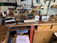
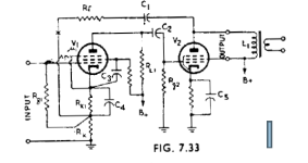
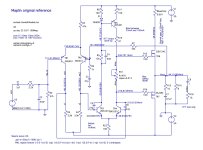
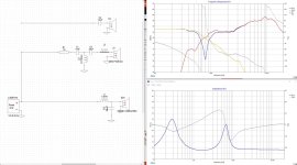
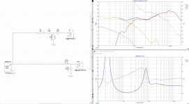
On the bench is a single-ended pentode (6CZ5). It’s configured with 36dB of negative feedback from the plate of the 6CZ6 to the cathode of the input valve. I dubbed this arrangement RDH733 after figure 7.33 in the Radiotron Designer’s Handbook. The RDH schematic shows negative feedback from plate to cathode in a two-stage amplifier. The input and output devices are both pentodes. The feedback loop does NOT include the output transformer.
RDH offers a mathematical analysis of the circuit to help estimate performance. The analysis is somewhat complicated by the feedback resistor Rk below the cathode resistor of the input pentode, which is not bypassed and provides additional negative feedback which reduces the input pentode’s gain. I used the RDH mathematics to put me in the ballpark and adopted a test circuit with potentiometers that allowed me to fine tune the feedback.
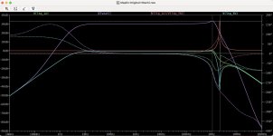
The chart shows total harmonic distortion on the vertical axis and output power on the horizontal axis for a 1kHz input signal. The orange line shows the result for a zero-feedback amp using the 6CZ5, the black curve with 36dB of negative feedback from plate to cathode. The negative feedback reduces distortion over a useful range of power.
I found I could get splendid test results (low distortion etc) that didn’t sound so good through my speakers. So I varied the overall feedback until I liked the sound, sometimes to the detriment of the measurements. As a rule of thumb, with my test speakers I achieved pleasing sound when I arranged THD to be 0.5% to 1.0% when the input signal was 1VRMS. The “sweet spot” will likely vary according to your speakers and your taste.
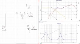
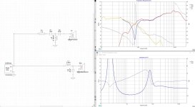
RDH offers a mathematical analysis of the circuit to help estimate performance. The analysis is somewhat complicated by the feedback resistor Rk below the cathode resistor of the input pentode, which is not bypassed and provides additional negative feedback which reduces the input pentode’s gain. I used the RDH mathematics to put me in the ballpark and adopted a test circuit with potentiometers that allowed me to fine tune the feedback.
The chart shows total harmonic distortion on the vertical axis and output power on the horizontal axis for a 1kHz input signal. The orange line shows the result for a zero-feedback amp using the 6CZ5, the black curve with 36dB of negative feedback from plate to cathode. The negative feedback reduces distortion over a useful range of power.
I found I could get splendid test results (low distortion etc) that didn’t sound so good through my speakers. So I varied the overall feedback until I liked the sound, sometimes to the detriment of the measurements. As a rule of thumb, with my test speakers I achieved pleasing sound when I arranged THD to be 0.5% to 1.0% when the input signal was 1VRMS. The “sweet spot” will likely vary according to your speakers and your taste.