I picked up an almost trash NAD C372 from the surplus shop and paid 30 bucks on it.
Upon inspection it's powering on but I noticed a smoke came from the Left channel.
Now due to its bad condition, I'm in doubt whether to repair it or use the trafo and heatsinks for DIY amp but I had this wish on my college days to have a NAD amp but no budget that time.
So I started my restoration (maybe the right word on it) removed the defective Left channel and there I found the job that I'm going to do is more than I expected.
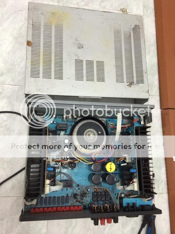
Dirt inside and outside.
There are stubborn dirt which are hard to remove so I use water and detergent soap and dry it with high pressure blower (bad idea but I'm doing it most of the time on cleaning some electronics board ensuring to dry it as soon as possible)
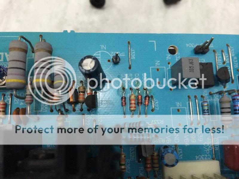
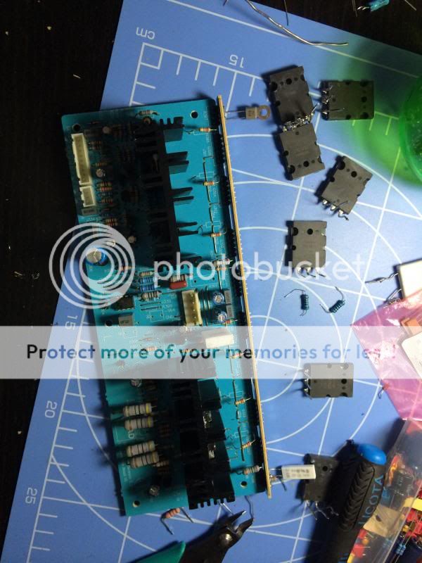
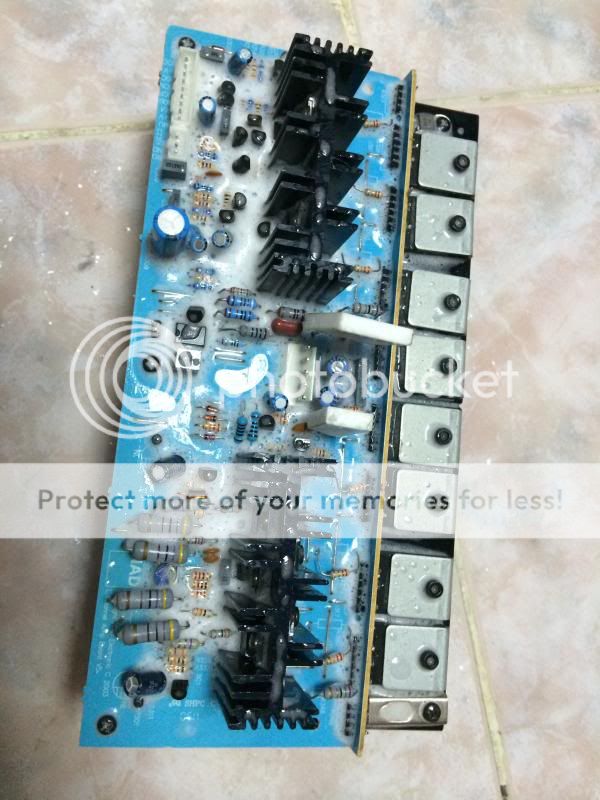
The amp module is badly tampered, some parts are not the correct value even the OP's are different.
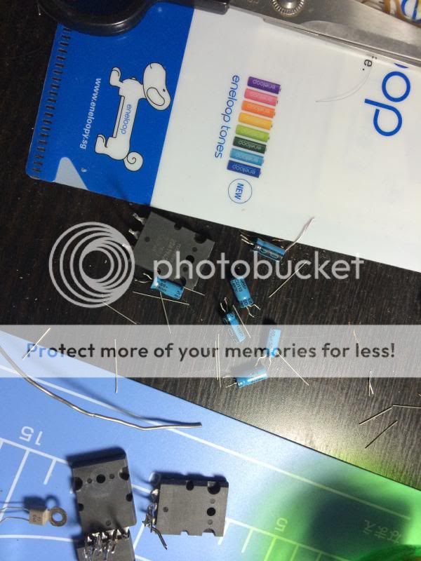
While I'm on it, I started to replace some "BADCAPS" (why Nad ruin their reputation by using a cheapo caps, to save money maybe ).
).
I don't know if I'm on the right track on doing this. Maybe I'm only wasting my time and money but I want to get it done.
I will post photos of my progress and I hope you share your thoughts and guidance on the Restoration on my Nad C372.
Upon inspection it's powering on but I noticed a smoke came from the Left channel.
Now due to its bad condition, I'm in doubt whether to repair it or use the trafo and heatsinks for DIY amp but I had this wish on my college days to have a NAD amp but no budget that time.
So I started my restoration (maybe the right word on it) removed the defective Left channel and there I found the job that I'm going to do is more than I expected.

Dirt inside and outside.

There are stubborn dirt which are hard to remove so I use water and detergent soap and dry it with high pressure blower (bad idea but I'm doing it most of the time on cleaning some electronics board ensuring to dry it as soon as possible)


The amp module is badly tampered, some parts are not the correct value even the OP's are different.

While I'm on it, I started to replace some "BADCAPS" (why Nad ruin their reputation by using a cheapo caps, to save money maybe
).I don't know if I'm on the right track on doing this. Maybe I'm only wasting my time and money but I want to get it done.
I will post photos of my progress and I hope you share your thoughts and guidance on the Restoration on my Nad C372
.
Last edited:


"bad caps" Well, any electrolytic more than 7 or so years old is bad. Many reasons we don't need to argue about here. NAD took some hits over reliability over the years for sure. Their level switching power supply was a known issue. You do need to realize they were trying to build a level or two in sound quality above their price point. Al in all, pretty good units. Truth in advertising: I have owned 4 NAD's. First two older receivers both failed. One was very old, the other not so. I have a new AVR and about a 5 year old CD doing just fine. Their sonic quality is almost the match of my "big" stuff but were about half the price. Your effort should be worth it. I hope you don't run against unobtainable parts.
Hello tvrgeek, thanks for the encouragement.
Last night I had a chance to put them altogether, I did not play music yet just turn on and observe if there's a smoke again.
DC offset is ok but I cannot lower the bias in the left channel. Also some resistors are heating up, it burned my finger actually.
Kindly help. Thanks in advance
BR,
Junie
.Last night I had a chance to put them altogether, I did not play music yet just turn on and observe if there's a smoke again.
DC offset is ok but I cannot lower the bias in the left channel. Also some resistors are heating up, it burned my finger actually
.

Kindly help. Thanks in advance
BR,
Junie
Last edited:


Hi Junie,
I am repairing my NAD c372 right now as well (go figure!). As it happens it went into protection mode last month during a long break in session of some new NHT towers. After contacting the NAD support line, I got straight through to Mr Moran below who has been very gracious in responding to my emails with help. Per his advice.We had several parties coming up so I replaced the c372 in our living room with a refurbished NAD c375bee (sounds great) from Spearitsound found at a fair price so I could work on it without pressure. You and I are having some similar issues so perhaps can get our units working even better!. My amp board is V5 which looks like your pictures. Notably No VR303(PCB)/VR301(schematic) on Left channel and PCB VR401(Right Channel), they are bypassed by a jumper
I bought (and installed)100v 10,000uf replacements caps from NAD per the message below (He suggested I order 4 - 100V 10,000 uf Capacitors to upgrade my unit: these would be the C724, C725, C727, C728 06-10312-00 10000uF, CD294 100V ±20% Alu Electrolytic Capacitors.
(NAD sells for $60 each, but they reduced the price to 37 each for me).
Mr Moran agreed that the 80v 10000uf caps had problems and should be replaced to avoid over heating and rupture, with the new 100v version. they are MUCH bigger.
After this, I too had trouble following the
"I. INITIAL ADJUSTMENT (No load connected)
A. OUTPUT OFFSET VOLTAGE
1. Connect a DC Millivoltmeter between TP303 & TP304 (pin 1 of IC 301A & gnd),
then adjust VR303(50kohms) to get a reading as close as 0V as possible, +/-30mV.
This can't be done on our versions as. No VR303 present on L channel Amp V5 Board, (or VR401 on right). TP303-TP304 Voltage about 1.0 volts intead of +/- 30mv, both before and after "C. ISC Sensitivity" adjustment Done . Note this is VR401 on the other channel
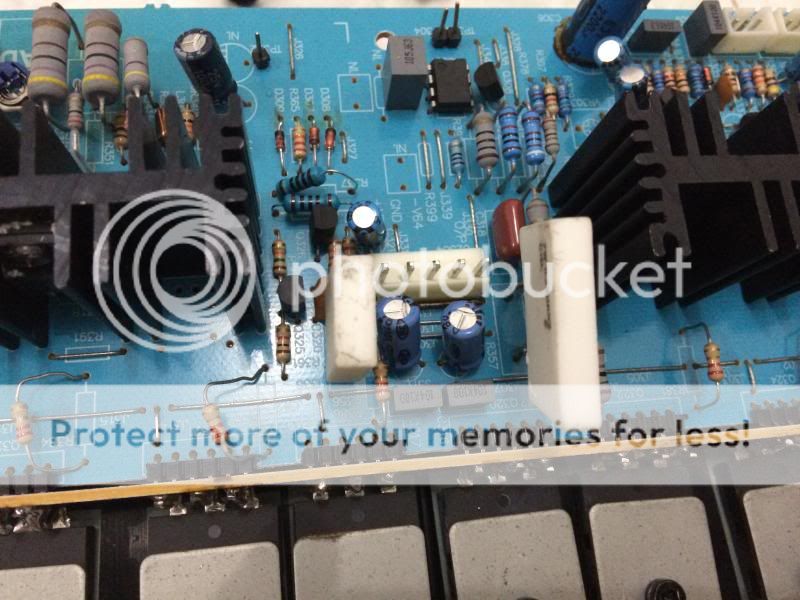
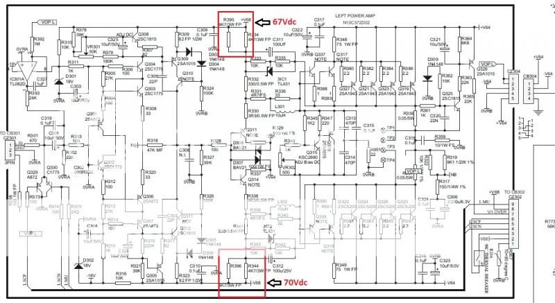
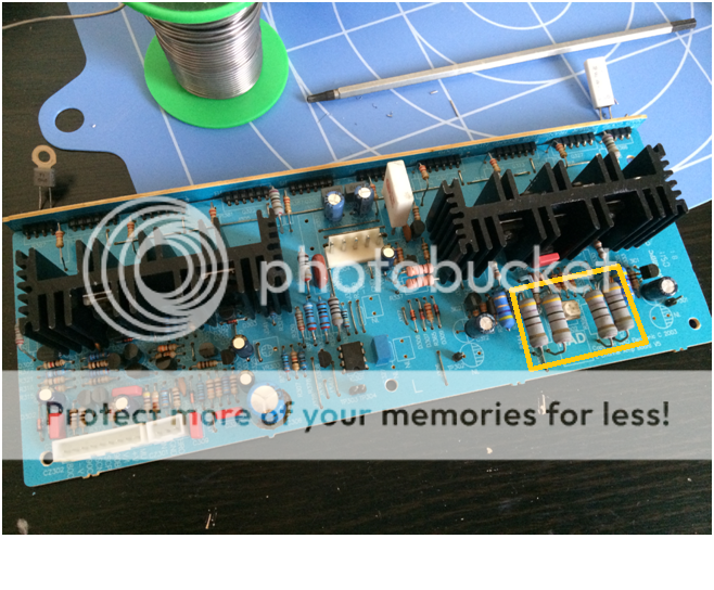
Also R334 and R395 seem very hot for NO load (165F/75C) with case open.
Note that the PCB for the LEFT channel amp has a MISPRINT. VR303 is missing and its location is jumpered short. I am planning to put a pot there to allow the calibration. Note also that on the schematic, VR301 corresponds to the PCB VR303, and VR401 for the RIGHT channel. I suspect this may be why the resistors are so hot and plan to replace them with 5W versions.
Tech support also recommended checking/replacing the DC servo IC IC301a/IC401a (TL082cp) these are readily available opamps and the feedback caps C312/C412 100uf 25v 105C (which you may already have done.)
I am pleased to hear your unit is working even without the bias adjustment done. I did not really want to hook mine up until I could get the correct adjustments, especially since I have a newer replacement in our living room. I may try it on some old speakers, and see how it scopes with some sine and square waves, but figure why not fix it up right the first time before closing it up. My wife and I have been very happy with its sound through our NHT mains, and Hsu sub. The c372 will go into our bedroom to replace an ancient Kenwood with broken speaker binding posts.
Anyway, your restoration looks fantastic. Enjoy your new sound.
I can advise how mine looks on my oscilloscope when I get around to completing the addition the VR301(303)/401, IC, capacitor replacement and those bloody resistors that can cook eggs! I can't believe that is right. How did you find the bad transistors? I'm checking with Mr Moran if the tech support people do not advise adding in the VR/Pots to match the service manual schematic.
here is some of the tech info from NAD
---
"If your unit has the 80 V 10,000 uf Capacaitors, please conact Mike in parts malguire@lenbrook.com to order 4 - 100V 10,000 uf Capaciators to upgrade your unit.
If I can be opf further assitance, please feel free to call me.
Best regards,
Bob Moran
Technical Product Manager
Lenbrook America
Ph: 800-263-4641 ext 4342
blmoran@lenbrook.com"
------------------
cheers
I am repairing my NAD c372 right now as well (go figure!). As it happens it went into protection mode last month during a long break in session of some new NHT towers. After contacting the NAD support line, I got straight through to Mr Moran below who has been very gracious in responding to my emails with help. Per his advice.We had several parties coming up so I replaced the c372 in our living room with a refurbished NAD c375bee (sounds great) from Spearitsound found at a fair price so I could work on it without pressure. You and I are having some similar issues so perhaps can get our units working even better!. My amp board is V5 which looks like your pictures. Notably No VR303(PCB)/VR301(schematic) on Left channel and PCB VR401(Right Channel), they are bypassed by a jumper
I bought (and installed)100v 10,000uf replacements caps from NAD per the message below (He suggested I order 4 - 100V 10,000 uf Capacitors to upgrade my unit: these would be the C724, C725, C727, C728 06-10312-00 10000uF, CD294 100V ±20% Alu Electrolytic Capacitors.
(NAD sells for $60 each, but they reduced the price to 37 each for me).
Mr Moran agreed that the 80v 10000uf caps had problems and should be replaced to avoid over heating and rupture, with the new 100v version. they are MUCH bigger.
After this, I too had trouble following the
"I. INITIAL ADJUSTMENT (No load connected)
A. OUTPUT OFFSET VOLTAGE
1. Connect a DC Millivoltmeter between TP303 & TP304 (pin 1 of IC 301A & gnd),
then adjust VR303(50kohms) to get a reading as close as 0V as possible, +/-30mV.
This can't be done on our versions as. No VR303 present on L channel Amp V5 Board, (or VR401 on right). TP303-TP304 Voltage about 1.0 volts intead of +/- 30mv, both before and after "C. ISC Sensitivity" adjustment Done . Note this is VR401 on the other channel
Also R334 and R395 seem very hot for NO load (165F/75C) with case open.
Note that the PCB for the LEFT channel amp has a MISPRINT. VR303 is missing and its location is jumpered short. I am planning to put a pot there to allow the calibration. Note also that on the schematic, VR301 corresponds to the PCB VR303, and VR401 for the RIGHT channel. I suspect this may be why the resistors are so hot and plan to replace them with 5W versions.
Tech support also recommended checking/replacing the DC servo IC IC301a/IC401a (TL082cp) these are readily available opamps and the feedback caps C312/C412 100uf 25v 105C (which you may already have done.)
I am pleased to hear your unit is working even without the bias adjustment done. I did not really want to hook mine up until I could get the correct adjustments, especially since I have a newer replacement in our living room. I may try it on some old speakers, and see how it scopes with some sine and square waves, but figure why not fix it up right the first time before closing it up. My wife and I have been very happy with its sound through our NHT mains, and Hsu sub. The c372 will go into our bedroom to replace an ancient Kenwood with broken speaker binding posts.
Anyway, your restoration looks fantastic. Enjoy your new sound.
I can advise how mine looks on my oscilloscope when I get around to completing the addition the VR301(303)/401, IC, capacitor replacement and those bloody resistors that can cook eggs! I can't believe that is right. How did you find the bad transistors? I'm checking with Mr Moran if the tech support people do not advise adding in the VR/Pots to match the service manual schematic.
here is some of the tech info from NAD
---
"If your unit has the 80 V 10,000 uf Capacaitors, please conact Mike in parts malguire@lenbrook.com to order 4 - 100V 10,000 uf Capaciators to upgrade your unit.
If I can be opf further assitance, please feel free to call me.
Best regards,
Bob Moran
Technical Product Manager
Lenbrook America
Ph: 800-263-4641 ext 4342
blmoran@lenbrook.com"
------------------
cheers
Last edited:
Thank you , junie ! Those pictures are "GOLD" to me.
This is the closest thing to my CFA design out there ... and you have one.
Your subjective assessment is to be expected , NAD can't come close to
a DIY amp of the same design (better layout/materials).
What a coincidence !!! WOW.
OS
This is the closest thing to my CFA design out there ... and you have one.
Your subjective assessment is to be expected , NAD can't come close to
a DIY amp of the same design (better layout/materials).
What a coincidence !!! WOW.
OS
I should mention that Mr Moran actually said the differences in sound between the c372 and the c375bee were not that great and upgrading the 10000uf caps was a good likely approach. The orginal 80v caps are white, the NAD 100v replacements are much taller and black. From Junies pictures, his unit may well have the 100v caps already.
I get ~1V at TP303/304; TP403/404 and since the VR NOT present, but jumpered short as with mine this can't seem to be changed.
Mr Moran reports that tech support does NOT recommend ading the VR.
I should mention I did check the speakere OUTs for a DC voltage and there was NOT any. The ~1 volt was at the above test points.
After replacing the 10000uf caps, R334/434 (4k7 3W) and R395/495 still run HOT at NO load (I measured 165F/75C) with case open. Mine show some surface changes.
So next is to pull the amp board and replace the DC servo op amp, replace the electrolytics and check the other transistors while i have open circuits. However, I suspect the unit is actually working right now (just it and my work bench are buried from cleaning the rest of the house for several parties, and overnight guests <G>)
Let me know if anyone wants to compare test readings. I have a Feb 2012 service manual, but my unit does not fully match what it says (mainly the Jumpered VR303/301 and VR401 location.
cheers and Happy New year
alan
Anyone have any suggestions as to how to get contact cleaner spray into the sealed Alps motorized volume pot?
Also,as with most of NAD amps of that era,my C740 has an electrolytic cap at the input. Mine is a 20uF/50V. Besides bypassing this cap with 0.1uF film type (as in the C372) what else can you suggest regarding this cap? Keep it? Change it for higher voltage low ESR? Maybe a bipolar type?
Cheers
Also,as with most of NAD amps of that era,my C740 has an electrolytic cap at the input. Mine is a 20uF/50V. Besides bypassing this cap with 0.1uF film type (as in the C372) what else can you suggest regarding this cap? Keep it? Change it for higher voltage low ESR? Maybe a bipolar type?
Cheers
Hi Junie,
I am repairing my NAD c372 right now as well (go figure!). As it happens it went into protection mode last month during a long break in session of some new NHT towers. After contacting the NAD support line, I got straight through to Mr Moran below who has been very gracious in responding to my emails with help. Per his advice.We had several parties coming up so I replaced the c372 in our living room with a refurbished NAD c375bee (sounds great) from Spearitsound found at a fair price so I could work on it without pressure. You and I are having some similar issues so perhaps can get our units working even better!. My amp board is V5 which looks like your pictures. Notably No VR303(PCB)/VR301(schematic) on Left channel and PCB VR401(Right Channel), they are bypassed by a jumper
Hello Alan, Happy New Year!
Yes I have V5 boards, I measured DC offset 5mv directly from the speaker terminals so no worries about it. The reason why NAD remove the pot because of the DC servo(I think, correct me if I'm wrong) but will try to put the 50K pots and see what will happen
I have Black big CAPS in 80V, I will contact NAD and I hope I can get the same discountI bought (and installed)100v 10,000uf replacements caps from NAD per the message below (He suggested I order 4 - 100V 10,000 uf Capacitors to upgrade my unit: these would be the C724, C725, C727, C728 06-10312-00 10000uF, CD294 100V ±20% Alu Electrolytic Capacitors.
(NAD sells for $60 each, but they reduced the price to 37 each for me).
Mr Moran agreed that the 80v 10000uf caps had problems and should be replaced to avoid over heating and rupture, with the new 100v version. they are MUCH bigger.
. After this, I too had trouble following the
"I. INITIAL ADJUSTMENT (No load connected)
A. OUTPUT OFFSET VOLTAGE
1. Connect a DC Millivoltmeter between TP303 & TP304 (pin 1 of IC 301A & gnd),
then adjust VR303(50kohms) to get a reading as close as 0V as possible, +/-30mV.
This can't be done on our versions as. No VR303 present on L channel Amp V5 Board, (or VR401 on right). TP303-TP304 Voltage about 1.0 volts intead of +/- 30mv, both before and after "C. ISC Sensitivity" adjustment Done . Note this is VR401 on the other channel
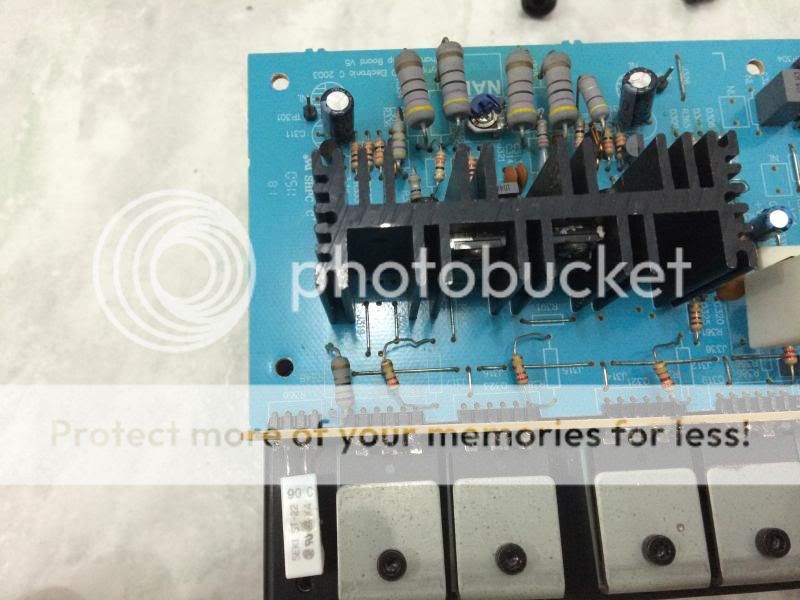
The right channel has a shorted D402 (18V Zener), and left channel upon physical inspection is already MURDERED by previous tech, OP's are different, Q403, Q404 and Q406 are faulty (I have a reading between Collector and Emitter) D308 and D309 are shorted, R337, R329, R331 and R341 are burned.
I found defective parts in the Mainboard, Q711, Q710 and some 1N4148 that in the plus/neg 68VDC a regulated supply of front end.
After replacing those parts the unit turned on.
Also R334 and R395 seem very hot for NO load (165F/75C) with case open.
Temporarily I increased the wattage of those resistors (5W but still it's hot to touch) even in the right channel. I will try to put the 50k pot and check if it will lower the temps of those resistors, but since you already contact NAD I'm willing to wait for their recommendationNote that the PCB for the LEFT channel amp has a MISPRINT. VR303 is missing and its location is jumpered short. I am planning to put a pot there to allow the calibration. Note also that on the schematic, VR301 corresponds to the PCB VR303, and VR401 for the RIGHT channel. I suspect this may be why the resistors are so hot and plan to replace them with 5W versions.
Tech support also recommended checking/replacing the DC servo IC IC301a/IC401a (TL082cp) these are readily available opamps and the feedback caps C312/C412 100uf 25v 105C (which you may already have done.)
.I did replaced the IC's even the IC in ISC.
I replaced all caps for reliability reason.
I did adjust the BIAS of both channel, I set it to 5mv (5mv to 6mv as per service manual).I am pleased to hear your unit is working even without the bias adjustment done. I did not really want to hook mine up until I could get the correct adjustments, especially since I have a newer replacement in our living room. I may try it on some old speakers, and see how it scopes with some sine and square waves, but figure why not fix it up right the first time before closing it up. My wife and I have been very happy with its sound through our NHT mains, and Hsu sub. The c372 will go into our bedroom to replace an ancient Kenwood with broken speaker binding posts.
Anyway, your restoration looks fantastic. Enjoy your new sound.
I'm also happy after repair completion I thought I cannot repair it since it's already from trash bin
.
Last edited:
Thank you , junie ! Those pictures are "GOLD" to me.
This is the closest thing to my CFA design out there ... and you have one.
Your subjective assessment is to be expected , NAD can't come close to
a DIY amp of the same design (better layout/materials).
What a coincidence !!! WOW.
OS
Hi OS,
Thanks for chiming in
 .
.After two days of breaking-in the new caps the amp has finally delivering it's fantastic sound, I decided to keep the NAD C372
. One of these days I will build one of your amps, I hope you won't mind me asking a lot of questions .BR,
Junie

Junie,
As in my earlier post, NAD advised against adding the 50K pot.
This clarifies what the DC servo IC does but it is odd that the service manual is not updated (perhaps they were already into the c375bee so felt it pointless to expend effort on a prior product):
"Dear Alan,
Thank you for your feedback. I have advised NAD of the misprint.
Unfortunately, NAD cannot go back to the factory for this model and review the Service Documents at this time. The factory is quite busy with current products.
For the DC servo IC, it will inject a small voltage on inverting input to offset the DC on the output so it may be difficult to measure anything meaningful.
Best regards,
Bob Moran
Technical Product Manager
Lenbrook America "
Given that your unit now sounds great, clearly the design is sound as is.
What voltage do you get between TP303/403 and TP403/404? Mine shows ~1V. If yours does also then likely the design now compensates elsewhere.
I must say, the internet is amazing, I'm near San Francisco, you are in Dubai and we are both working on the same Canadian integrated amplifier!!<G> You must feel tremendous satisfaction at restoring a $1500(US) amp purchased for $30.
cheers.
alan
TP303/TP304: 2.3Vdc (Left channel)
TP403/TP404: 0.8Vdc (right channel)
Though the unit is sounding great I will stop using it for sometime till we find the reason why those parts are heating up...it's very hot.
I will check again tomorrow and will update here.
Yeah we can change ideas through the medium which has not existed long ago. And now it's almost midnight here while you will have your lunch soon .
TP403/TP404: 0.8Vdc (right channel)
Though the unit is sounding great I will stop using it for sometime till we find the reason why those parts are heating up...it's very hot.
I will check again tomorrow and will update here.
Yeah we can change ideas through the medium which has not existed long ago
. And now it's almost midnight here while you will have your lunch soon .- Home
- Amplifiers
- Solid State
- NAD C372 to restore or not