OPA1612 from Aliexpress, no counterfeit but why so cheap?

After working with some OPA1612 on my recent Topping PA5 D01 Module replacement project (at ASR),
a friend sent me a few OPA1612 opamps he ordered when they were in stock since i couldnt get them anywhere.
alongside with some aliexpress el`cheapos for like 2 buck a piece instead of 7..8 bucks for a genuine part.


i expected them to put some cheap crap in there, so i didnt wanna use them.
but was curious whats in there, so i opened one up.. surely they have put a tl072 or ne5532 in and relabeled it..
turns out, after extracting the Silicon Die, they are genuine.

Do they not meet the manufacturers specifications and are rejects or something else?
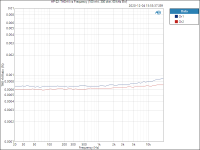
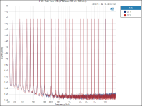
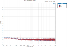
nothing my budget equipment can measure, but they worked fine, didnt have any louder hiss than the original parts and didnt oscillate or anything, even power draw was about the same.

this was from two different sellers at two difference price points on aliexpress, it doesnt mean everyone on there sells genuine parts.
i now ordered some more for like 80 cents a piece to see, whats going on with them. gotta wail til they arrive.

hearing them vs. the genuine part thats in spec, isnt conclusive either, its differences are so minor, my ears cant pick them up.


Original (mouser):
e-CAMView_slg6h7xnyD.jpg

from a device that used them (actually the topping i mentioned above, extracted from the module)
, the damage to the right might be due to my extraction methods.. this chip is barely a millimeter in height and im not using any chemicals.
e-CAMView_yRq9xU3HZe.jpg

Aliexpress seller 1
e-CAMView_iZIC86G8BN.png

Seller 2

e-CAMView_2v5ejO3UXO.jpg


(zoomed out, not to scale anymore)
for comparison, a genuine OPA1656
e-CAMView_eduvzjgvg3.jpg

Ti NE5532
e-CAMView_ePdV66W06X.jpg

TL072
e-CAMView_JxvDlIdIWq.jpg
  • Like
Reactions: Zung and kipman725

Ideas input for a Interstage driven 300B SET

Hi,

First post here after reading many interesting and enlightening topics. I’ve just finished a simple 45 amplifier, and was so positively surprised I decided to build a second amp. This so the 45 can do what I built it for: drive my headphones in the office.
I just made the mistake of trying it on my speakers and despite their low efficiency the sound is so addictive the amp is not moving to the office until I’ve built a proper “speaker” amp!

So here we are, I’d like to build a 300B amp: I’ve acquired a pair of tango NC20 interstage transformers (original make) and have a set of Audio-note Output transformers (single ended). All I need is a schematic 🙂

I do like the idea of keeping everything DHT and simple, because then it’s easier to grasp given my limited knowledge and philosophically I like simple: also this would allow me to study the effect of swapping individual components to tailor the sound. (I’m not looking for something that measures well per se, it should sound well, not for opening that discussion🙂 )

I like the 45 sound but that probably has too little amplification to keep it two stages, which would be the preference, also one could avoid coupling capacitors but am open to be convinced otherwise. Should I look at a 10y? EML 30a?

In any case curious to hear peoples thoughts.

Cheers!

Matthew

Bliesma T34 Tweeter

hi there,

I know that some of our users here have pre-ordered some of those new Bliesna T34 tweeters which are shipping now.

It's a brand new company, the owner and inventor was former developer at Morel and later product-engineer at Accuton.

Now he came up with his very own product. The T34 tweeter.
A 34mm (1.3") aluminium/magnesium alloy dome tweeter with varaible thickness.

Have a look at the specs yourself:
http://www.bliesma.de/product.html

In this thread I'd like to hear experience with this tweeter and discuss this product.
The price is 580€ (ex. VAT) for a pair.
  • Like
Reactions: DblAA

Aleph P1.7 assembled board

Aleph p1.7 completed board for sale.
Solid brass bar keeps all mosfets equally hot, relays are itt, gain fets are harris devices, attenuator section uses sfernice resistors and some nos siemens 0.1% resistors. In/out capacitors are roederstein mkc, capacitance is smaller than advices 10uf, but if load is not tough its alright.
Ps photos are from construction, bad soldering on adc chip is corrected.
Asking 230 euro.
Board size 20x30 cm


20230820_180043.jpg
20230924_114029.jpg

WTB Rythmik Audio 15" driver

Does anyone have somewhere lying around an 15 inch Rythmik Audio subwoofer driver, does not matter which model DS1501, DS1502, DS1510, etc. Black or silver, does not matter.

I have an damaged driver in my E15 and need a new one and looks like Rythmik Audio does not sell the drivers separately any more.

I'm located in Europe but have an shipping address also in US and UK.

Marantz Superscope CD 330 can't record on left channel

I recently bought on eBay a Marantz CD 330 portable cassette recorder sold as in working condition but with a couple of issues, in part solved but one remains, so I decided to seek advice here.

There was a VU-meter needle stuck at half height, but I solved that by loosening its back screw a little. Now the needle is back at -20dB.

There was a stray black (grounding) wire broken which caused a subtle hum, but I've found its place and soldered it back, hum is gone now.

Also, I put new belts on it as the tape counter was not working because of a belt too loose, and also the others didn't look good. Now the transport works like a charm.

BUT, after changing the belts I did some recording tests and discovered that the left channel is not recording, while the playback of pre recorded cassettes is even in both channels. With the monitor selector on Source I can see the signal coming on both channels, so the problem should be on the left channel recording circuit. Any suggestions? What should I check first in your opinion?

Apart from the dirt collected in 40+ years and the recording issue, the deck is working and looking fine. I would like to find a solution for that problem, so any help is appreciated!

Thanks a lot in advance,
Lorenzo

Attachments

  • 20240514_220429649.jpg
    20240514_220429649.jpg
    143.1 KB · Views: 80

For Sale XRK TPA 3255 Ref

I don't know what Iwas thinking. I'll never get these small SMD parts on. I'll end up throwing a fit. Selling the amp and buffer boards as well as the Mouser supplied parts shown in the attached invoice. As I remember it was 99% available/complete, the BOM that is. I also looked for the VR that was totally unavailable. It was Ebay but really did seem kosher. There is a mystery part I purchased outside of Mouser that I can't ID. You'll be 99.5% there. Id like to get $150 shipped.
1000001956.jpg

Attachments

12v to dual rail converter

Hi, im having a go at building a dc-dc converter, that will take 12v and output +55v, 0v and -55v.
This is the circuit i am using, with a hand wound toroid transformer:
IMG_0493.jpeg

Unfortunately, im not reading any voltage on the 50-0-50 outputs, however using a basic oscilloscope with channel 1 attached to point 1, and channel 2 attached to point 2, with oscilloscope ground to point G, i believe that the oscillation side of the circuit is working ok (this reading was taken without the transformer attached, so just testing the oscillating circuit)
IMG_0491.jpeg
IMG_0493.jpeg

Im not quite sure why channel 1 is not swinging as much as channel 2. Both read as having a frequency of 35khz.
I may have wound my transformer wrong, anyone know how to wind a transformer like this? I doubt i can purchase a specific one for this.
Any ideas appreciated, better circuits etc.

Any VCV users here?

Hi,
After years of resistance to 64bits OS i finally sold my soul to the devil... and first opportunity to use a soft in this is VCV.

I spent 2 weeks playing with the thingy and i must say it blows my mind.

Not that i'm unfamiliar with modular synths and discovered the unlimited sound design capability this kind of instruments offer as i'm a long time owner of Clavia's NordModular and have a small and humble analog 'frankensynth' diy modular i started 10 years ago and which slowly evolved since, but the sound quality and ease of use of VCV is incredible for something free.

And polyphonic modules are a god send i could only have fantasy about in analog. Not even talking about the possibility offered by the software to interface with hardware world ( cv/gate, midi or audio either in or out).

It even gives access to emulation of some Serge panels, Buchla's inspired modules and synth voices ( Music Easel emulator! YEEESSS!), real time samplers, wavetable... even lunetta's modules are availlable ( as well as Klee sequencer... it seems some electro-music.com people have stamped their signature in modules developement).

It's so good i've not even installed the (free too) Buchla's modulars vst emulation yet to play with!

For those which have more experience with it have you find some limitations? In all honesty at this point i don't find any (for what i do with modular) and really wonder if i will ever continue to invest time in building modules for my analog one.

Threshold SA/1 vs SA/12E

Hello everyone, I'm new to this forum, but have been following some of your threads. This question should be direceted to Mr Pass himself, but if anyone has any experience with an sa/1 comparison to the sa/12e, could you please share. I am considering one of these amps, but not sure what the differences in character are. I have heard the sa/1's and absolutely loved them. Just wondering if the sa/12e are an extension of the sa/1's or do they give anything up for the extra power? the sa/12e amps seem to be extremely hard to come by, even compared to the sa/1's. To Mr. Pass, I really wished you had put the meters on the sa/12e also, they looked gorgeous, besides gives you a sense on where the amplifier is in output, just my opinion. Thank you to you all and hope to get some feed back.

Port Question

After building a couple of near field speakers with small Mark Audio drivers I'm planning on building some with larger CHN 110 units.
Interested in two boxes but wondered what the difference of the port location and size will have on the two below. What would the sound difference be.

Attachments

  • Fenlon-110.png
    Fenlon-110.png
    17.5 KB · Views: 110
  • OV93.jpeg
    OV93.jpeg
    120.9 KB · Views: 95

For Sale SIGMA - Lateral MosFET Amplifier

Here i im selling SIGMA reference class audio amplifier that sounds very good as is using exicon lateral mosfets and works with +/-48 VDC to +/-50VDC power supply.

For sale is complete pcb boards, populated, tested and working.

2pcs SIGMA amplifier populated boards
2pcs PSU 2x4700uF/63VDC Rubycon USR
1pcs SOFTSTART with input for on/off button
2pcs SPEAKER PROTECTION boards with high quality relays and high quality air inductor and golden connectors for speaker.

As i im from Europe it will be good if buyer is from EU so there will be no additional costs if buyer is from EU Union.

Price is €400,00 and free shipping inside EU Union Countries.

Please contact me PM to exchange data.

Thanks for your time 🙂

Attachments

  • reference-class-mosfet-amplifier-sigma-slika-131354001.jpg
    reference-class-mosfet-amplifier-sigma-slika-131354001.jpg
    59.6 KB · Views: 418
  • reference-class-mosfet-amplifier-sigma-slika-131354000.jpg
    reference-class-mosfet-amplifier-sigma-slika-131354000.jpg
    76 KB · Views: 396

C Audio 606 Repair.

Halfway through fixing this C Audio SR606. Looks like it's an early version with relays on the driver boards and copper heatsinks. . This one was completely dead when it arrived....

Found out there was a bad fuse holder in the back. Temporary fix by bypassing it and relying on fuse in plug .

Powered up on dim bulb... Slowly ramped up till the soft start released. This was a bit hit and miss as second attempt it went dead again... Found a power switch wire bad joint. Then I finally got it fired up.

It then goes straight into protection.. 75v DC on channel B. Very low DC offset on the other side. Still on dim bulb so lower voltage. I can hear two relays click. Sounds like one is the soft start and the other from the good channel.

Removed the power wires to the MOSFETs and pulled out drive board. Measured driver board output and still got huge DC. So fault on this board . Found at least 6 small signal transistors shorted. BF422/23s. I'm hoping there is no shorts on the MOSFETs. They did test fine with a quick test and fuse wire not blown. .

These boards do not have any component markings on the PCB at all.

I used a white pen to mark the shorted transistors

If I don't get this repaired this still plenty of spares for my other C Audio amplifiers.

Attachments

  • 20240516_190029.jpg
    20240516_190029.jpg
    254.1 KB · Views: 83
  • 20240516_184515.jpg
    20240516_184515.jpg
    461.6 KB · Views: 76
  • 20240516_174708.jpg
    20240516_174708.jpg
    358.2 KB · Views: 82
  • 20240516_115218.jpg
    20240516_115218.jpg
    564.4 KB · Views: 81
  • 20240516_114157.jpg
    20240516_114157.jpg
    586.6 KB · Views: 83
  • 20240516_185709.jpg
    20240516_185709.jpg
    399.1 KB · Views: 80

Neurochrome HP-22: A high-performance DIY headphone amp for less than $100

It turns out that high-end DIY actually can be affordable. Who knew?! 🙂 Build your Neurochrome HP-22 headphone amp for less than $100!

I have just opened up for preorders of the HP-22 circuit board and will offer a preorder discount until the boards arrive in stock. I expect to start shipping them by December 22, 2020. If you use FedEx or UPS for the shipping method, you'll be ready to build just after Christmas. You can preorder your HP-22 circuit board here: HP-22 – Neurochrome

The HP-22 mounts as a shield atop a Texas Instruments OPA1622 evaluation module (EVM) to form a complete high-performance headphone amp. The amp provides 200 mW into 300 Ω, 360 mW into 50 Ω, and 200 mW into 32 Ω at -130 dB (0.00003% THD). The multi-tone IMD residual measures below -146 dBr (referenced to 100 mW into 300 Ω).

Tweakers will be delighted to know that the HP-22 lends itself to opamp experimentation. Should you prefer to use a different opamp than the specified LME49720, have at it! Just make sure to select one that's stable at +10 dB gain and capable of driving a 1 kΩ load impedance cleanly.

Speaking of gain... The gain of the HP-22 is +10 dB. Should you wish for a higher or lower gain, all you need to do is to change a resistor.

The OPA1622 EVM comes with rubber feet, so the HP-22 will sit neatly on a tabletop even without a chassis. As it contains the input RCA connectors, the volume control, and the output connector the HP-22 can be used without a chassis if desired. It can even be powered by a pair of 9 V batteries. And, naturally, if you wish to mount the HP-22 in a chassis, you can easily mount it to the front panel using the volume pot mounting hardware and connect the RCA connectors with wires.

The images below show my prototype build. The hockey puck was included in the picture as a scale indicator. The HP-22 is rather tiny. Maybe if I was a better marketeer, I would claim that the proprietary Neurochrome puck is made from a unique and patented rubber compound, which provides vibration control and resonance dampening. 🙂

You can find all the performance graphs and specs on the HP-22 product page: HP-22 – Neurochrome
All measurements were performed with the HP-22 powered by a Neurochrome Preamp Power Supply.

Tom

Attachments

  • HP-22_Proto_wPuck.jpg
    HP-22_Proto_wPuck.jpg
    193.1 KB · Views: 1,203
  • HP-22_Proto_Front.jpg
    HP-22_Proto_Front.jpg
    197 KB · Views: 1,202
  • HP-22_Proto_Rear.jpg
    HP-22_Proto_Rear.jpg
    183.9 KB · Views: 1,203
  • HP-22_Proto_wTIbox.jpg
    HP-22_Proto_wTIbox.jpg
    199.2 KB · Views: 1,207
  • HP-22_Proto_PCB.jpg
    HP-22_Proto_PCB.jpg
    253.7 KB · Views: 1,180
  • HP-22_ THD+N vs Output Power (1 kHz, 300 ohm, 20 kHz BW).png
    HP-22_ THD+N vs Output Power (1 kHz, 300 ohm, 20 kHz BW).png
    33.4 KB · Views: 583
  • HP-22_ THD+N vs Frequency (100 mW, 300 ohm, 60 kHz BW).png
    HP-22_ THD+N vs Frequency (100 mW, 300 ohm, 60 kHz BW).png
    26.1 KB · Views: 382
  • HP-22_ Multi-Tone IMD (AP 32-tone, 100 mW, 300 ohm).png
    HP-22_ Multi-Tone IMD (AP 32-tone, 100 mW, 300 ohm).png
    71 KB · Views: 404
  • HP-22_ Residual Hum & Noise.png
    HP-22_ Residual Hum & Noise.png
    48.8 KB · Views: 430

Concrete Fidelity. My first DIY speaker build; cast from concrete

I recently built some desktop speakers from concrete, and I am trying to understand my measurements.
I am quite happy with the overall sound, but they are definitely missing some base.

1715720212954.png


I am using a Dayton Audio DS135-8 woofer with a Peerless Tymphany BC25SC08-04 tweeter and crossed them at 1700hz in a sealed 3l enclosure. (Datasheets attached)

Below my far field on axis response measured at 1m
1715719768846.png


Here my near field measured response of the driver

1715719844787.png


1715719940622.png


How do I further smoothen the response and extend the bass? Do I simply need a sub?
This is my first DIY speaker so, excuse if there are any obvious omissions or mistakes.

Attachments

Looking for an existing sub design to build

I own a pair of the GR Research H Frame 2x12 OB Subs. I never had wonderful bass in my room and these dont seems to be great either. I am suspecting it is my room. I am interested in building an existing proven design that is know to work well. I would like to stay with 12 inch woofers (2 is good). I have all kinds of amps so I am not worried about that end of it. I'll buy what I need and money is not s much an issue. Recommendations?

Beast Mini

So I am listening to a podcast with pa that dropped 11 days ago. (Link) Apparently pa is working on a J113 version of the mythical beast. 256 Jfets. :nod: Looks like the worldwide stock of J113 might drop a bit! If this is being discussed elsewhere, let me know!

Hey pa, if you need anyone for prototyping and testing, ill take the bullet. :rofl:

Best,
Jose

turntable/record player and unwanted reception of broadcast sw stations

Hi
I heard often about unwanted radio stations by playback of records (radio moscow effect), especially in combination with phono preamplifier concept's without lowpass capacitors and inductive resistors arround the input gain stages. One example of radio sensitive RIAA head preamplifier is the EAR 834 (EAR834), see schematic by the URL http://www.goodsoundclub.com/Site_images/EAR-834PT-1.gif
Amazing for me is, that in some cases the unwanted reception by shorting the inputs will be still present. The reason could be a parasitic inductivity between mainboard GND and metallic enclusure chassis

On the web I don't find any informations about theoretical background and the reasons for unwanted AM demodulation in the short wave (SW) aera - in most cases between 6 MHz and 7 MHz (wavelength 49m and 41m). I think, I don't know the right keywords resp. the english slang words about this topic in Google.

Perhaps one of the members know web addresses about this topic.

Best thanks for your advices

Best Regards
Andreas Kirschner

Help wiring these German transformers

10F65D7E-C2B0-4CBA-87F9-E41CB7D24596.jpeg
Hi,
I purchased these German line output transformers some time ago, they are marked 019.1 and come from a broadcast mixer comissioned by the RFZ (the East-Germany BBC. Well known for their lovely preamps, I purchased these for some pres I have from these old mixers.

I assume these are matching transformers, but Its impossible to find a diagram and I mysef have never wired/tested a transformer.

Any help in wiring this would be much appreciated! It would go from the preamps unbalanced output into the trafo and out to the XLR mounted on the chassis.

Thanks a bunch!
-- MusicWorks

Replacement for IRF130 IRF9130

Hi folks,

in a friend's active speakers from the early 90s, work with IRF130 and IRF9130 VMOSFETs on the power amp modules. In one of the modules both VMOSFETs have failed (seemingly due to electric overvoltage). So far as we can find, the parts are not available from reliable sources anymore and other sources seem rather doubious...

Please, anyone, if at all possible, please advise which parts would work drop-in compatible or what we can or have to do to repair the power module! We do actually have the power amp's schematics if needed.

Thanks and Regards,
Winfried

Adding a small 5V fan for cooling any components to add for elecrtical noise isolation ?

I have been modifying the power supply on the analogue board on a naim AV2 and this will result in a lift of pre reg DC supply to the board LM317 and LM337 regulators. So I will move from a pre reg DC supply from +-20V to +-24V when the post reg supply is +- 15V. I have ordered some copper pads to add the the back of the existing heat sinks, which I will nylon bolt to the heat sinks. But want to keep the unit cool, so want to add a small fan to help the temperature rising too high internally and can

I can pick up a 4.3V DC supply near where I will mount the 5V fan. Other than say a 0.1uf cap to GND on the +ve side of the fan any better ways to isolate any electrical noise ?

Telefunken voltage stabiliser tubes - application note in German?

I am looking for a german language original (if it exists) of the english version of Telefunken's 1960s application note for its voltage stabiliser tubes. The english version (here: https://tubedata.altanatubes.com.br/other/Telefunken/Telefunken_NewVoltageStabilisers_1966.pdf) leaves a bit to be desired and I'd like to work from the german original, if it exists and if anyone has a copy to hand.

Mid-Tweet x-over point for a 3-way design?

I am working on a powered speaker that consists of the following:

Two 15-inch woofers
Two 6.5 inch professional style mid-bass drivers

Again - this is a powered design with a fully active x-over. No passive components to worry about here. The dual 15-inchers will be powered by a TPA3251, the two 6.5's will be powered by a TPA3116 and the tweeter will have it's own TPA3116. Each amp board with individually-adjustable gain/level.

The two 6.5 inch pro mid units have a Fs of around 100hz. I plan to cross the 15 and midbass units over around 220hz. This puts me in the neighborhood of where baffle effects start to kick in if I am not mistaken. And since the dual 15's are on their own amp (with adjustable gain), it should make this adjustment easy.

The two 6.5 inch midbass units will be mounted MTM style (above the dual 15's) with a yet-to-be determined tweeter (although I am 99% certain I know which one I want)

These 6.5 inch midbass units play pretty damn good past 3k.

I currently have THIS tweeter in my Aliexpress basket:

https://www.aliexpress.com/item/1005005687082677.html

For those who do not want to click into the link, here are some basic specs:

These are basically china clones of the Scanspeak D3004/6640 from what I understand
Beryllium dome tweeter
FS = 500Hz
High freq range extends WELL into the 25k region
Faceplate diameter is just over 100mm

Before anyone jumps to conclusion: these are some of the finer things that come out of china. I have personally heard a set of these and they are extremely well behaved tweeters mounted in solid aluminum faceplates - the quality is absolutely top tier. China has their good, bad and ugly. This is their exceptional stuff.

The effective radiating surface of the 6.5 inch midbass units is barely over 5 inches. My plan is to cross the midbass units over to this tweeter at somewhere between 1200 and 1800hz.

Getting up towards 2000 means getting close to the center-to-center limit possible with this combination. Closer to 1200 means the half wavelength is still larger than the center-to-center AND width of the midbass effective radiating surface.

The response of the tweeters I am looking at starts to drop slightly around 1500 - so crossing around 1200 seems like I may be pushing my luck a bit.

My active x-over design is currently a purely analog 12db linkwitz/riley active filters on protoboard. I have not soldered in the components for the mid-tweet x-over yet.

So... am I in the right ballpark here? Would 1500 be reasonable? At 1500, the half-wavelength is around 4.5 inches - about a half inch short of what the C-T-C distange would be from midbass to tweeter (and slightly less than the effective radiating surface of the midbass). 1200 puts the 1/2 wave larger than both, but I am riding the enge of where the FR of the tweeter starts to drop a bit. 1200 is also still over twice the Fs of that driver - so not like I am pushing my luck too much here. Worse case scenario, I need to add a simple shelf filter?

Or am I completely mis-calculating things?

music and artificial intelligence

Hi everyone .
There was a story on the news recently that I think is known to most of the world's population.
The last Beatles song that has never been published before has found new life thanks to artificial intelligence. They managed to reconstruct a ruined song using other Beatles songs.
I wonder if it's possible to do the same thing with old, poorly made recordings. I'm not referring to the Beatles but to any other musical group that wasn't lucky enough to record their music with decent equipment.

Crossover help needed - too fast phase shift around 3.7-4-7Khz

Hey guys, I'll need some help since this is my first build of a bookshelf speaker and crossover.

Basically, I've some weird phase shift around 3.7-4.8Khz (not sure if this is normal but I can also see some deep there in the FRD file) after measuring the speaker with the crossover which I built.

I am pasting below the REW measurement + the crossover design so hopefully some of you guys can help me out since as I said this is my first built and I am not much experienced to determine what may causing this issue.

I wonder, is it because the high impedance at around same frequency around 4khz as seen from the Xsim screenshot? And how I can avoid this?

Thank you in advance!!!

Attachments

  • Response with phase issues.png
    Response with phase issues.png
    83.6 KB · Views: 124
  • Xsim screenshot.jpg
    Xsim screenshot.jpg
    447.2 KB · Views: 121

AC filtering questions

Hello girls and boys....
i have two toroidal transformers (230/45V - 300VA)... What i was thinking is to make a filtering device for AC power similar to Felicia power conditioner (two transformers back to back)... Problem is, i don't have center tap in my primary on any of those two transformers...
So i was thinking maybe at the output where i get 230/240VAC out, to put two resistors from each output of the second transformer to ground (to put my "earth" in the middle of those two outputs from the second transformer (sch attached - version "A").....
so my question is, do i need those resistors - maybe just caps would be enough to put my earth potential in the middle..... that would be Version "B"... or do i need anything at all (version "C").....
... electronics after this would be a dac that has a separate power supply consisting of a switching pre-regulator and regulator of some sort after (probably linear PSU).. i would probalby put a streamer on this also once i sort out it's power supply block and turn it to linear PSU.......
any suggestions....

Attachments

  • back2back.jpg
    back2back.jpg
    57.4 KB · Views: 241

IcePower 400A2 + SWR SM-400

Hi there,

Going down a rabbithole trying to integrate an IcePower 400A2 class D module in an old SWR SM-400 amp. Bought the amp with a completely blown power amp so it seemed more efficient to get a module.
PSU:
the transformer brings the +/-55v and +/-15v

The module asks for max +/-69v / min +/-45v and +/-12 (VDD/VSS) and Vdrive which sits +15 above the negative power rail.
All of the voltages except mains are regulated by 78xx/7912

I don’t get any sound and kind of afraid I already blew the module disturbing it’s finicky nature by my some stupid testing.

Probing on the +12 rail I get -2v drops in 0,4s intervals, the neg rail correlates. All the other voltages seem stable. The DCerror pulls low, when VD/VS is applied it starts flashing

Any leads? Not sure how to go on

Thanks a lot for your time!

I’ll attach the diy preregulator (which is followed by a 7815) and other relevant documents

Attachments

For Sale Carver C-4000 Preamp

SOLD!!! Carver C-4000 Preamplifier
Excellent physical and working condition. Super flexible with every Carver top of the line feature available. Multiple phono inputs(MM and MC) multiple tape loops. Every feature works perfectly. Surround and Sonic Holography settings including rear channel amps. Come see and play with it.
First $500 takes it.

Attachments

  • PXL_20240110_204021049.jpg
    PXL_20240110_204021049.jpg
    365.3 KB · Views: 111
  • PXL_20240110_204047422.MP.jpg
    PXL_20240110_204047422.MP.jpg
    431.9 KB · Views: 106
  • PXL_20240110_204052143.jpg
    PXL_20240110_204052143.jpg
    348.2 KB · Views: 95
  • PXL_20240110_204031969.jpg
    PXL_20240110_204031969.jpg
    356 KB · Views: 95
  • PXL_20240110_204059908.jpg
    PXL_20240110_204059908.jpg
    349.7 KB · Views: 98
  • PXL_20240110_204119273.jpg
    PXL_20240110_204119273.jpg
    352.2 KB · Views: 93
  • PXL_20240110_204125568.jpg
    PXL_20240110_204125568.jpg
    362.8 KB · Views: 113

Interesting article about mains filter amplifying noise

https://www.emcstandards.co.uk/mains-filters-might-not-perform-to-spec-and-can

I've just traced down my 20kHz noise in my JCM amp.. turns out it's external and/or being spat out of the IEC filter I have (schaffner 6A jobbie).

With the amp off, the filter on and connected to the PT primary.. there's big spike at 20kHz that I can measure through the insulation of the negative mains output from the filter. There's little on the primary side.

The issue is that the Toroid then couples that directly onto the heater and B+ lines. Mainly the heater 6.3Vac that I'm using.

Edit - replacing the IEC filter, well it's still there.. so obviously external.. still an interesting article.
  • Like
Reactions: gerrittube

Arduino-Based Tube Amp Control System

I'm sharing my design/code of an Arduino-based tube amp control system. Code and photo are attached. Here are the things it does:

1. Fault monitoring. It continuously checks for fault conditions (e.g. tube over power, HV too high, etc.) and immediately shuts the amp down if one occurs.
2. Display current conditions. I have it displaying plate voltages for input tubes, output tube plate currents and powers, B+ voltage, and tube hours.
3. Bias tubes. I have it set up to bias my input tubes by adjusting screen voltage and bias output tubes the usual way, but my amp is an A2 amp so grid bias is a positive voltage.

Hardware Description

Let me walk through the photo. I'm not going to bother making a schematic but everything is simple enough if you follow instructions/documentation from Arduino and Adafruit.

In the middle is the Arduino Nano Every with an Adafruit MCP4728 four-channel DAC daughter board. You don't need the DAC if you don't want tube bias under microcontroller control.

On the left of the Arduino is a prototype board with a HV amp chip so that the DAC outputs can get scaled up to the voltages I need for biasing the tubes (~100V for the input tubes and ~35V for the output tubes). My particular amp needs positive bias voltages so I am using an HV264 chip, but you would probably need some sort of inverting HV op-amp setup to get negative voltages and you would need to modify the code to make sure it moves the right direction to increase/decrease tube operating conditions and that the gains it uses to calculate changes are correct. It's flexible but you definitely want to run some tests before you hook it up to a real tube.

Additionally, on that board to the left you can see a 7805 regulator and behind it an IRL520 which is used as an open-drain output to drive the SSR that controls the main AC power input for the amplifier. That's what the Arduino uses to shut things down if a fault condition is detected. Obviously, for this to work the Arduino will have to be always powered and it is in control of the rest of the power.

Mounted to the board above the Arduino are all of the voltage dividers that I use to sample B+ and the plate voltages of the input tube. I do filter audio frequencies from output of that divider so the Arduino is not sampling instantaneous plate voltage of the input tube but average voltage. I do the same for output tube plate current sampling.

The board on the right (and the black brick next to the Arduino) is all circuitry that I use to sense plate current. Most amps don't need any of that because cathode current sensing is much easier and simpler. I needed to do high-side plate current sensing because this A2 amp has both grid current and plate current in the cathode current, so I needed to measure plate current alone. I used a TLP7920 and a bunch of supporting circuitry to do that.

The display is a "RGB backlight negative LCD 20x4 + extras (RGB on black) [ID:498]" from Adafruit also using the "i2c / SPI character LCD backpack[ID:292]". Anything you want to display can be displayed there. As you can see I'm displaying B+, input tube plate voltage, and output tube plate currents and powers, and I have an hours meter for the output tubes.

It is so nice to have a display like this that gives you a bunch of measurements at a glance when you are experimenting (especially with transmitting tube B+ voltages). All of my future work is going to be done like this.

Software Description

I'll just do a very high level description of the software.

All functions are non-blocking. They check and see if work is ready to be done. If not, they return immediately with the expectation that they will be called again when the work is ready.

The program has three main states: AMPLIFIER_OFF, AMPLIFIER_WARMUP, and AMPLIFIER_ON. The main loop simply calls the associated main task for each state.

The amplifier off task simply updates the heartbeat LED and waits for the power button to be pressed.

The amplifier warmup task initializes DAC outputs, sets up the display, turns on the AC power to the amp and then runs a countdown timer on the display so that the user knows when amp is ready. It also starts bias adjustments on any tubes that are past their warmup time, checks for fault conditions, and keeps the heartbeat LED going.

The amplifier on task reads ADCs and updates the display, checks for faults, biases the tubes, and keeps the heartbeat LED going.

Upon shutdown, the processor stores the last good bias values in EEPROM and uses them as initial values on the next startup.

The header file contains many values that can be configured for the particular tubes used and other settings. I have it set to slowly ramp voltage on bias adjustments over a period of 5 seconds and adjust every 30 seconds. There are a lot of tube specific settings for the bias control in the header file.

The code is set to check for a bias button to be pressed to initiate the bias adjustment process. I simply wired it to GND for it to bias every 30 seconds.

Code is less than 1000 lines total.

One last note about sampling current/voltage: The amp I made this for was class A SE. I did some experiments to see if I needed to wait for musical silence to do the calculations to make bias adjustments. Basically, I played loud electronic music with sustained bass notes and I paused and un-paused while I watched to see if that would perturb any of the voltages/currents on the display. None of the values seemed to change at all on this amp, so I made the decision to just adjust bias whenever. If you are going to use it on a push-pull AB amp, I'd run a similar experiment. If it turns out that the average current changes by an amount that makes you uncomfortable, I'd implement a silence detection circuit that hits that bias button input every time there is silence. Then all of the calculations will be based on low/no signal conditions.

Attachments

  • AmpControl.zip
    AmpControl.zip
    7.8 KB · Views: 171
  • IMG_20240412_141527498.jpg
    IMG_20240412_141527498.jpg
    640.2 KB · Views: 417

For Sale 10awg bulk speaker cable

I have hundreds of feet of Rapco Horizon speaker cable. This is just about a garden hose size cable, round with 2 copper conductors and amazing flexibility. Quite heavy of course. Probably the best bulk large conductor pure copper speaker cable out there.

Each conductor is 10awg, 2 per run with some twine nearby to keep cable round. Made in USA.

Each of the 2 wires are 105 strands of 30AWG annealed copper. Very easy to work with.

Offering for $1.50 per foot plus shipping.

Specs are here https://www.rapcohorizon.com/images/document/10ga.pdf

Message me if interested with desired length and zip code, shipping from San Diego fyi.

Attachments

  • 1000000588.jpg
    1000000588.jpg
    937 KB · Views: 105

I blocked my Floyd Rose Tremolo

Frankly I couldnt stand it anymore. Breathe on it and the pitch modulates, as in just the finger effort to turn one of the little trim screws changes the pitch as much. Stuck with mushy light gauge strings, pulling against 3 heavy springs, the stupid locking nut that doesnt, the bar that isnt a machine tolerance fit in the socket, wiggles no matter how hard you tighten the cap - no more - "I'm so done with you"!

Glad to read on line you can just do this. One day I'll get a solid tail guitar; this'll have to do till then. Looking at candidates I think "it has springs... nope!"

IMG_0071.JPG

WinISD is giving me a a crazy high SPL

I have an old school Blaupunkt subwoofer from when they were a part of Bosch and made good quality stuff. They have since gone bankrupt and someone is piting that name on china junk. It's like new since it's been sitting in my closet. The problem is, WinISD is giving the SPL as 116db, when it is 93db. I tried unchecking the calculate box and putting in 93 db, but it still models the speaker at 112db 1w/1meeter with a 0db transfer function. Is this why I'm getting such a high cone excursion? When I add a 12 db static filter the over excursion problem goes away, but I'm not sure that means cone excursion won't be an issue. I also wonder if the issue may be caused by a misprinted parameter in the manual.manual. But since they are out of business there is no tech support. Thanks for any help with this issue.

Here are the drive's specs. Any look seriously off?

POWER HANDLING 180 Watts rms
540 Watts peak
SENSITIVITY 92 dB (2.83V/1m)
89 dB (1W/1m)
FREQ. RESPONSE 20 - 2kHz
NOMINAL IMPEDANCE 4 ohms
MAGNET WEIGHT 40 oz
MOUNTING CUTOUT DIMENSIONS 9.2 inches (234mm)
MOUNTING DEPTH 5.0 inches (127mm)
AIR VOLUME DISPLACEMENT 0.17 cu.ft.
VOICE COIL DIAMETER 2.0 inches
THIELE-SMALL PARAMETERS
Resonance frequency 30 Hz
Total Q factor (Qts) 0.35
Electrical Q factor (Qes) 0.36
Mechanical Q factor (Qms) 7.02
Volume equivalent compliance (Vas) 2.75 cu.ft.
Linear excursion (Xmax) 0.20 in. (1 direction)
DC resistance (Re) 3.56 (ohms)
Force factor (BL) 10.2 (Tm)
Effective cone area (Sd) 320 (sq.cm.)
Compliance (Cms) 540 (uM/N)
Moving mass (Mms) 61 g

Budget wave guide tweeter plans for 2.5 tower speaker upgrade - Peerless BC25SC06-04 1" Textile Dome Tweeter

I just finished up my Pinnacle Classic Gold Tower speaker XO and tweeter upgrade. I am so impressed with the budget tweeter I used that I wanted to share how I did it. I fried one of the OEM Vifa metal dome tweeters during testing with REW. Stupid me! Based on advice I received in the thread like at the end of this post, I was told to optimize a tweeter with the 8” woofer I should use a wave guide. Most of the recommended components were above my pay grade. My goal was to use a very efficient tweeter with an L-Pad that would work well with the two OEM 8” woofers in this 2.5 tower. I put the project aside. I then came across a the Peerless BC25SC06-04 1" Textile Dome Tweeter for $14 each that had a surprising flat response. The result, the Pinnacle towers now perform at a level that is way above my expectations and a the current moment they are my favorite speaker in my collection. I wanted to share so here is a basic plan for what I did and some additional info on this budget tweeter. I would love to hear back from anyone who gives this tweeter a try!

My previous thread on this project: https://www.diyaudio.com/community/...tion-for-a-2-5-using-2-8-inch-woofers.404675/

Attachments

  • Peerless_Tweeter Specs.JPG
    Peerless_Tweeter Specs.JPG
    65.2 KB · Views: 90
  • Peerless_Tweeter_7523_s.jpg
    Peerless_Tweeter_7523_s.jpg
    353.1 KB · Views: 87
  • Plans.JPG
    Plans.JPG
    103.7 KB · Views: 82

Coaxial output not working on Marantz CD4000

I have a Njoe Tjoeb modded Marantz cd4000, Always used either through headphone output or RCA out to amplifier.
Just bought a Hifiman ef499 and wanting to use digital output via coaxial cable.
I have plugged cable in both ends, selected Coax on the ef499, but no sound.
Checked ef499 with digital input from phone and PC and they work fine.
Is there a switch I need to set on the cd4000 to activate digital output?

Reduce mouth resonance in horn

I'd thought to title this "How to Slay the Ravenous Bugblatter beast" but that would be too obscure. However, might as well explain it. In the series "Hitch-Hiker's Guide to the Galaxy," a traveler would carry a towel in case he met up with said beast. Upon meeting one, you'd cover your eyes and be safe. For the Beast was so stupid, if you couldn't see him, he couldn't see you. OK, now to bend this around to something having to do with horns ( or waveguides, for this thread they shall be synonyms 😀 )


I've read many of the threads here about the various debates that rage over how to design or treat a horn. I claim no audio expertise. Just as well, I see how Dr. Geddes and others are treated! 🙄 But I do actually own a horn system (Yorkville Unity U15) and have tried some of the various tweaks. Do they work? Maybe...I have almost no way to test. But others do....


Once a horn and driver(s) is selected and the speaker built, we have a complete system. But this horn still has potential distortions. For time being, let us consider only those due to shape of the horn: (1) the elusive higher order modes (HOM) reduced by careful design of horn, smooth throat, and stuffing the horn with 30 ppi reticulated foam, preferably after paying royalties to Earl Geddes! (2) Diffraction, not the HOM type (which seems to me to be a special case of diffraction occurring inside the horn) but the type affecting nearly all speakers due to "sharp" edges on the corners, creating a 2nd delayed sound source. And finally the one I wanted to treat in this thread: (3) mouth reflection, also called pipe resonance or reflection. Unlike HOM, this is not controversial. Due to the impedance mismatch between horn mouth and open air, there is a partial reflection of the signal, resulting in a continuous "reverb" to the signal. It is reasonable to expect the extent of the reverb is a function of the dimensions of the horn as well as what, if any, mouth termination is done. It is also possible that some listeners actually LIKE the reverb, considering it part of the horn sound. However, I consider it an unnatural special effect I'd rather listen without.


How, then, to reduce the reverb? There are no doubt many methods. Proper horn design is one. But not everyone can have a horn with a mouth that opens up like a gigantic morning glory 🙂 What DIY, preferably cheap, methods then are available? Enter the lowly towel.


I won't go into detail about it, it is covered in other threads, but one of the best tweaks appears to be simply wrapping a towel around the sharp mouth edge. As good, I presumed, would be a towel "ring" around a mouth otherwise in a baffle as on a U15. The goal is to better match the impedance to open air.


If this tweak has any downside, it must only be the necessity to turn a smooth speaker into something that looks like it has rolled up laundry on it. There are no doubt ways to improve cosmetics, but I will skip that for now.


Ultimately, after this long winded intro, is what I'd like: Is anyone aware of any testing, other than the very limited amount done, that show the efficacy of the towel tweak alone, for a given driver and horn combo? Or better, to try a variety of similar tweaks, and give results as impulse response or similar? This would seem a very simple series of tests but would need a (quasi) anechoic chamber for best results.

Behringer CX2310 Mismatched slopes. Other options?

Howdy all. Been building up a system in my studio for mixing, trying to keep costs and latency down if possible. It consists of some Kali LP6v2 and a DIY 12" woofer/bass module/speaker stands that the monitors sit on. It all sounds quite lovely and provides a great budget mixing platform on a budget, at least when it's all functioning properly. I've tried various unbalanced DSP solutions but didn't care for them, mostly input voltage limitations. I had a behringer CX2310 lying around that seemed like a perfect fit until I hooked it up.

It sounded fine, but kind of off. I went ahead and measured the speakers and the slopes looked off. I bypassed the speakers and just measured the unit with a loop back into motu m4. Oh my, the slopes are totally different for the left and right outputs. I assume this is from age or tolarences or just being one of the behringer products that they didn't care much about. I don't see repair on this as being worth it, so I'm open to some suggestions. Just need 2 in and 4 out.

Do you think I should expect the same results from other analog crossover units? I understand it's a bit dated tech but it doesn't add any latency and they can be found cheap. Thomann appears to a few options, the minidsp is cheap but looks to not meet what I need voltage wise. The 204 looks better, but none match the might of the analog untis which look to be on average of 22dbu in.

While I'm not interested in using this behringer unit, I'd be curious to know why the slopes could be off, but still look so clean?

20240515_142323.jpg

For Sale Mundorf AMT23, Open Baffle Tweeters (and crossovers)

mundorf amt.JPG

Mundorf AMT Tweeters -
Location : UK (Berkshire)
RRP: £1,200 (pair) + crossover bits
PRICE: £600 (ONO)

These are the AMT 23 DIPOLE version of the tweeter.
So perfect for your -best-parts-you-can-get Open baffle build.


Crossover parts - there for you to cannibalise - including L-pads
They are 14k (supertweeter crossovers) - but you may well want to crossover a lot lower.
Included because you might aswell have them, and use what you need 🙂

Another source lost to the 500IQ webmaster.

First it was Partsexpress, which is so bad that I have to use Google to find anything on it... Now PartsConnexion is impossible to navigate. The website is functionally non-functional when you can't even click on menus you want because the programming for screen sizes doesn't scale correctly nor operate a frame for mouse registration the same size as the menu. The banners are half the page... What the **** are these people thinking? Who are these designers? Are they TRYING to make sure their businesses fail???? Is it sabotage from Amazon plants? Seriously, how can anyone be dumb enough to think you're going to sell anything if people literally can't get to the product pages or even a thumbnail? I'm sure they tell their bosses it's user error and they aren't responsible for economy changes.

bh187-spongebob.gif

New idea: RE084 drives RS282

Hi everyone, I am pursuing a new pair of monoblocks. RE084 driving an RS282. Would like your thoughts on the design. I borrowed the operating points RE084 from Ale and the RS282 from RobDHT.

My main concern is if the RE084 will have enough swing to drive the RS282 to full output. My goal is to get 10-15 watts of clean class A using my DAC streamer as source (2Vrms). So, any thoughts on this would be appreciated. I have attached the schematic, curves and data sheets for each tube.

Thanks!
Pat

Attachments

  • re084 curves.png
    re084 curves.png
    185.9 KB · Views: 320
  • RE084 data sheet.pdf
    RE084 data sheet.pdf
    103 KB · Views: 135
  • rs282.pdf
    rs282.pdf
    576.9 KB · Views: 108
  • rs282 curves.png
    rs282 curves.png
    398.4 KB · Views: 358
  • “2024-02-22 4.png
    “2024-02-22 4.png
    54.3 KB · Views: 394

LPS Mods - USB Audio PCIe Card

Hey, I have one of these LPS on order from AliExpress:

https://www.aliexpress.com/item/1005004989616614.html

Some of the description:

The materials used are very sophisticated, high-speed and low-dropout 4A Schottky rectifier diode, the output tube is ON tube king 15034, TL072 dual op amp, NOVER 6800uF/35V main filter capacitor. Integrated PCB design with output overcurrent and overload function to improve power supply safety.

I was thinking of upgrading / replacing a few of the components to better quality parts. It's to power a pretty critical device for me, am audio USB PC Card as external power. Thinking caps - but looking at the stuff, the opamp TL072 maybe, not sure, interested in any suggestions.

Screenshot 2024-05-01 164839.jpg


Screenshot 2024-05-01 164950.jpg

"BUGBIAS" circuit to solve blocking distortion for capacitor coupled tube amplifier

I am in my way of designing my singled ended amplifier and come across the topic of blocking distortion. I am in search of the way to mitigate the problem and meet BUGBIAS from YouTube and Facebook. This circuit is proposed by BUG AMP in 2020. If anyone has tried the circuit or would like to make some comment, please share your view on it. Thanks.

Attachments

  • Bugamp bias circuit.jpg
    Bugamp bias circuit.jpg
    188 KB · Views: 354
  • Like
Reactions: Doug De Young

8" woofers 40-250hz

Hi

Im taking over a big 3-way speaker build with the cabinets already build. The baffles can be done as I want within limits ofcourse.
Now im looking for 8" speaker-candidates and hope to get some help from you...

The speakers will have 4x8" per side and an MTM section in the middle with 2x Purifi 6,5" and a Mundorf AMT29. (well tested by myself in different setups).

The 8" woofers have around 60-70 litres of volume per 2 speakers. And Im open for using them as closed or ported.
These 3-way speakers will have big open baffel subs taking care of the frequencies up to 40-50hz so the 8" have to be at its best between 45-50 - ~250hz.

Any suggestions? Purifi 8" are the dream but cost to much. Im thinking maximum around 300euro/dollars per speaker.

8" or more like ~235mm is the max diameter of the speakers.

Happy to hear your thoughts! / Theo

Zaph ZRT 2.5 sealed opinions?

Hey Folks, I'm thinking about going for this build, being a happy user of ZD5 for years. I was thinking about 2.5 sealed, so looking for some opinions from people who built this specific variant, if any. My room is fairly small, so having 68L monster with double vents might be an overkill. I also ran into this thread which now bothers me:

https://www.diyaudio.com/community/threads/zaph-madisound-zrt-2-5-problem.311454/

Interest in 3D printet holders for the UcPure by IanCanada

Interest in 3D printet holders for the UcPure by IanCanada:

Made this thread for any intereste related in buying the 3D printed holder.

I would consider making a small patch for those interested in buying a set.

Pricing and shipping to come.

Please post a reply if your are interested and in how many sets.

1 set = 4 pieces (2 upper + 2 lower holder) to build a single UcPure supply. The holders will be one color only.

Attachments

  • Skærmbillede 2024-04-14 kl. 20.35.58.png
    Skærmbillede 2024-04-14 kl. 20.35.58.png
    1 MB · Views: 130
  • Like
Reactions: andersos

Roland Cube 40 distorted output

TL;DR, You are probably several orders of magnitude smarter than me and i need your help to fix my old Roland amp.

I bought a 1981 Roland Cube 40 several weeks ago as spares or repair. The amplifier is very clean cosmetically ( near mint ) but the seller said the sound would crackle and distort. I just assumed this would be dirty pots or a bad transistor at worst and didn't read too deeply in to it.

To cut a long story short, the job quickly grew arms and legs and i basically started strategically shot-gunning components that i thought might be guilty of causing the fault. As it stands ive replaced almost everything on the PCB aside from the resistors and diodes and the fault persists. I know this approach is less than ideal but my testing equipment and knowledge is severely lacking.

What is the fault?

When the guitar is strummed, a very noticeable crackle/distortion can be clearly heard among the sound of the guitar. The fault is more pronounced with bass notes and pickup output has an effect too. The amplifier has two channels, one clean and one overdrive. The overdrive channel barely does anything aside from boosting the volume slightly, i have no reference with these amps however i found someone doing a demo of one of these amps online and the overdrive channel is noticeably different when compared to my own. Worth noting that the crackle/distorted fault persists on both channels on my amp but is more prominent on the overdrive channel.

Just to rule out some suggestions people might call out, il save you some time,

Ive tried changing the guitar leads, ive tried different guitars, ive tried different plug sockets in the house, i had a brand new Fane 10" speaker that i installed, i changed the speaker wire from PCB to speaker inside the amp, i ran a solid state rackmount pre amp in to the "Main In" jack on the amp and the problem was still there. Aside from the three-core mains plug and transformer wires, ive basically re-wired the entire thing, i even made up little 3pin plug harnesses for the transistors that mount to the amp chassis. ( i did find structural corrosion on a few wires which is what prompted me to address the wiring )

Ive tried almost everything.

Important things to note,

: There was OEM security marks on all fasteners inside the amp, im quite sure that no one has touched this amplifier other than me.
: I used NOS transistors from suppliers i trust, some have modern substitutes available but i wanted to play it the way its laid out on the schematic to keep it simple.
: The unit had roughly seven carbon comp resistors, some of which had drifted drastically, ive replaced these with 1/2w carbon film so i know the values are where the schematic wants them to be.
: There is a fused resistor in the circuit which ive checked and seems to be intact with some basic continuity checks
: Two wires from the transformer are providing 26vac each, go to the rectifier bridge and split to +35v and -35v, the 35v can be seen on the filtering caps and several transistors too.
: Electrolytics are all new Nichicon UFG/UFW bought from Mouser, filter caps are also Nichicon but not UFG/UFW. (cant remember which ones i used) I replaced these due to general wear and tear, some readings almost outside the acceptable tolerance. (43 years old Sanyo caps from factory)
: The performance of the amplifier has not changed in any way, shape or form after going Mach 10 with the parts cannon.

From what ive read, this is a Quasi-Complimentary design? I only do this at an entry level hobbyist stage so im not very clued up on circuit design. My background is vehicle mechanics so i trust myself to play the remove and replace game but im certainly not geared towards circuit layout and electrical engineering. I buy gear for spares or repair quite often and i usually have a high success rate but this one is beyond me. I had most of these parts already so all this has cost me so far is time.

I have a multi meter and some hopes and dreams, please help! (picture taken before work was carried out)

DSC_9960.jpg

Attachments

15" Woofer Choice for K-402 based MEH

Hi all..

Looking for 2 x15" woofers for a 2-way K-402 based MEH. Would like the following specs:

8 olm with a free air resonance around 25-35 Hz and a Qts of 0.25-0.3

Found 11 here:

http://www.loudspeakerdatabase.com/search/15.0_size_in_15.0/8_z_8/25_fs_35/0.25_qts_0.30

I've modeled a couple in Hornresp (see below) that seem readily available in the US.

My questions are: 1. Can someone double check my input parameters to make sure I'm modeling these correctly for a MEH? ...and 2. If #1 is satisfied, what are you favorites of the ones below and why (I'm trying to learn)? ...and 3. Are there other woofers I should consider not on the list above?

I really hope the Dayton one will work as it's the cheapest option... they all look really similar to me 😕

K-402 Horn w/ TAD 4002


K-402 Horn w TAD 4002.jpeg


K-402 horn with two Eminence KAPPA PRO-15LF-2 15" woofers-Total Power


K-402 Horn w TAD 4002_1.jpeg


K-402 horn with two Eminence KAPPA PRO-15LF-2 15" woofers - Displacement


K-402 Horn w TAD 4002_2.jpeg


K-402 horn with two Eminence KAPPA PRO-15LF-2 15" woofers - Input Correct?


K-402 Horn w TAD 4002_3.jpeg


K-402 horn with two Dayton Audio PA380-8 15" woofers - Total Power


K-402 Horn w TAD 4002_4.jpeg


K-402 horn with two Dayton Audio PA380-8 15" woofers - Displacement


K-402 Horn w TAD 4002_5.jpeg


K-402 horn with two Dayton Audio PA380-8 15" woofers - Input correct?


K-402 Horn w TAD 4002_6.jpeg

4 channel diy Amp

1702169290789.jpg

Hello for everyone,
I have recently developed this 4 channel module based on LM4766, I have already a module for powering up a subwoofer mid and high's but don't have enough power for powering up an 8 inch sub only good for about a 5 inch subwoofer.
https://www.ebay.de/itm/325598018547?hash=item4bcf277bf3:g:BlMAAOSw5KpkKCbh&amdata=enc:AQAIAAAAwIMf3ZXyegKd/KV1KqTSkxHlTCZgUp2mxp4uU2nvoyKN5207KlbNhn0COUkDrdBztyAiuQIcuGBHD080SobUrEe7eUlgQo9CXUHMuG9qDEvH63ksYlY1Rm2tw5AZrv8Bxwvpe2M9wqmYcCCGaFLyA6DW9m9CMHfEuJQ+lyEcOR+/KKwFb5Xk5jclNEs2Cj7+Xo6kp48XeTpcEA7qD7wmd+4031/CKJp3GoHVb+ai61HBp7BHz40oSG6783o/rCKZZg==|tkp:Bk9SR5DEtJOKYw
So I develop this module, it's outputs are configurable as 4x50; 2x100; or 2x50 more 1x100, I would like to know if there more people interested on this and if there is someone that know a good power supply SMPS running on 12V that produce +30V -30V to use in car áudio?
In the worst I develop my self,Regards

Attachments

  • 1702169290729.jpg
    1702169290729.jpg
    427.7 KB · Views: 114
  • 1702169290743.jpg
    1702169290743.jpg
    430.6 KB · Views: 114

Questions about crossover for my project

I'm building two 3-way boxes, each box will have a crossover board separating the signals for each speaker. I will use the following woofers, midrange and tweeters:
tweeter mid woofer
I would like to know which crossover is ideal for this kit, because when I chose one I found its filter very strange for the midrange (from 1000hz to 7000hz).
What are the ideal frequency cuts for a 3-way kit? Can I find a crossover on AliExpress with the ideal frequency cuts?
From the specifications I find of crossovers on the internet, how can I calculate at what frequency the frequency cut will be?
Projects by fanatics, for fanatics
Get answers and advice for everyone wanting to learn the art of audio.
Join the Community
507,713
Members
7,885,454
Messages

Filter

Forum Statistics

Threads
406,099
Messages
7,885,454
Members
507,713
Latest member
Stone95