I'm sharing my design/code of an Arduino-based tube amp control system. Code and photo are attached. Here are the things it does:
1. Fault monitoring. It continuously checks for fault conditions (e.g. tube over power, HV too high, etc.) and immediately shuts the amp down if one occurs.
2. Display current conditions. I have it displaying plate voltages for input tubes, output tube plate currents and powers, B+ voltage, and tube hours.
3. Bias tubes. I have it set up to bias my input tubes by adjusting screen voltage and bias output tubes the usual way, but my amp is an A2 amp so grid bias is a positive voltage.
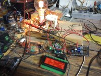
Hardware Description
Let me walk through the photo. I'm not going to bother making a schematic but everything is simple enough if you follow instructions/documentation from Arduino and Adafruit.
In the middle is the Arduino Nano Every with an Adafruit MCP4728 four-channel DAC daughter board. You don't need the DAC if you don't want tube bias under microcontroller control.
On the left of the Arduino is a prototype board with a HV amp chip so that the DAC outputs can get scaled up to the voltages I need for biasing the tubes (~100V for the input tubes and ~35V for the output tubes). My particular amp needs positive bias voltages so I am using an HV264 chip, but you would probably need some sort of inverting HV op-amp setup to get negative voltages and you would need to modify the code to make sure it moves the right direction to increase/decrease tube operating conditions and that the gains it uses to calculate changes are correct. It's flexible but you definitely want to run some tests before you hook it up to a real tube.
Additionally, on that board to the left you can see a 7805 regulator and behind it an IRL520 which is used as an open-drain output to drive the SSR that controls the main AC power input for the amplifier. That's what the Arduino uses to shut things down if a fault condition is detected. Obviously, for this to work the Arduino will have to be always powered and it is in control of the rest of the power.
Mounted to the board above the Arduino are all of the voltage dividers that I use to sample B+ and the plate voltages of the input tube. I do filter audio frequencies from output of that divider so the Arduino is not sampling instantaneous plate voltage of the input tube but average voltage. I do the same for output tube plate current sampling.
The board on the right (and the black brick next to the Arduino) is all circuitry that I use to sense plate current. Most amps don't need any of that because cathode current sensing is much easier and simpler. I needed to do high-side plate current sensing because this A2 amp has both grid current and plate current in the cathode current, so I needed to measure plate current alone. I used a TLP7920 and a bunch of supporting circuitry to do that.
The display is a "RGB backlight negative LCD 20x4 + extras (RGB on black) [ID:498]" from Adafruit also using the "i2c / SPI character LCD backpack[ID:292]". Anything you want to display can be displayed there. As you can see I'm displaying B+, input tube plate voltage, and output tube plate currents and powers, and I have an hours meter for the output tubes.
It is so nice to have a display like this that gives you a bunch of measurements at a glance when you are experimenting (especially with transmitting tube B+ voltages). All of my future work is going to be done like this.
Software Description
I'll just do a very high level description of the software.
All functions are non-blocking. They check and see if work is ready to be done. If not, they return immediately with the expectation that they will be called again when the work is ready.
The program has three main states: AMPLIFIER_OFF, AMPLIFIER_WARMUP, and AMPLIFIER_ON. The main loop simply calls the associated main task for each state.
The amplifier off task simply updates the heartbeat LED and waits for the power button to be pressed.
The amplifier warmup task initializes DAC outputs, sets up the display, turns on the AC power to the amp and then runs a countdown timer on the display so that the user knows when amp is ready. It also starts bias adjustments on any tubes that are past their warmup time, checks for fault conditions, and keeps the heartbeat LED going.
The amplifier on task reads ADCs and updates the display, checks for faults, biases the tubes, and keeps the heartbeat LED going.
Upon shutdown, the processor stores the last good bias values in EEPROM and uses them as initial values on the next startup.
The header file contains many values that can be configured for the particular tubes used and other settings. I have it set to slowly ramp voltage on bias adjustments over a period of 5 seconds and adjust every 30 seconds. There are a lot of tube specific settings for the bias control in the header file.
The code is set to check for a bias button to be pressed to initiate the bias adjustment process. I simply wired it to GND for it to bias every 30 seconds.
Code is less than 1000 lines total.
One last note about sampling current/voltage: The amp I made this for was class A SE. I did some experiments to see if I needed to wait for musical silence to do the calculations to make bias adjustments. Basically, I played loud electronic music with sustained bass notes and I paused and un-paused while I watched to see if that would perturb any of the voltages/currents on the display. None of the values seemed to change at all on this amp, so I made the decision to just adjust bias whenever. If you are going to use it on a push-pull AB amp, I'd run a similar experiment. If it turns out that the average current changes by an amount that makes you uncomfortable, I'd implement a silence detection circuit that hits that bias button input every time there is silence. Then all of the calculations will be based on low/no signal conditions.
1. Fault monitoring. It continuously checks for fault conditions (e.g. tube over power, HV too high, etc.) and immediately shuts the amp down if one occurs.
2. Display current conditions. I have it displaying plate voltages for input tubes, output tube plate currents and powers, B+ voltage, and tube hours.
3. Bias tubes. I have it set up to bias my input tubes by adjusting screen voltage and bias output tubes the usual way, but my amp is an A2 amp so grid bias is a positive voltage.
Hardware Description
Let me walk through the photo. I'm not going to bother making a schematic but everything is simple enough if you follow instructions/documentation from Arduino and Adafruit.
In the middle is the Arduino Nano Every with an Adafruit MCP4728 four-channel DAC daughter board. You don't need the DAC if you don't want tube bias under microcontroller control.
On the left of the Arduino is a prototype board with a HV amp chip so that the DAC outputs can get scaled up to the voltages I need for biasing the tubes (~100V for the input tubes and ~35V for the output tubes). My particular amp needs positive bias voltages so I am using an HV264 chip, but you would probably need some sort of inverting HV op-amp setup to get negative voltages and you would need to modify the code to make sure it moves the right direction to increase/decrease tube operating conditions and that the gains it uses to calculate changes are correct. It's flexible but you definitely want to run some tests before you hook it up to a real tube.
Additionally, on that board to the left you can see a 7805 regulator and behind it an IRL520 which is used as an open-drain output to drive the SSR that controls the main AC power input for the amplifier. That's what the Arduino uses to shut things down if a fault condition is detected. Obviously, for this to work the Arduino will have to be always powered and it is in control of the rest of the power.
Mounted to the board above the Arduino are all of the voltage dividers that I use to sample B+ and the plate voltages of the input tube. I do filter audio frequencies from output of that divider so the Arduino is not sampling instantaneous plate voltage of the input tube but average voltage. I do the same for output tube plate current sampling.
The board on the right (and the black brick next to the Arduino) is all circuitry that I use to sense plate current. Most amps don't need any of that because cathode current sensing is much easier and simpler. I needed to do high-side plate current sensing because this A2 amp has both grid current and plate current in the cathode current, so I needed to measure plate current alone. I used a TLP7920 and a bunch of supporting circuitry to do that.
The display is a "RGB backlight negative LCD 20x4 + extras (RGB on black) [ID:498]" from Adafruit also using the "i2c / SPI character LCD backpack[ID:292]". Anything you want to display can be displayed there. As you can see I'm displaying B+, input tube plate voltage, and output tube plate currents and powers, and I have an hours meter for the output tubes.
It is so nice to have a display like this that gives you a bunch of measurements at a glance when you are experimenting (especially with transmitting tube B+ voltages). All of my future work is going to be done like this.
Software Description
I'll just do a very high level description of the software.
All functions are non-blocking. They check and see if work is ready to be done. If not, they return immediately with the expectation that they will be called again when the work is ready.
The program has three main states: AMPLIFIER_OFF, AMPLIFIER_WARMUP, and AMPLIFIER_ON. The main loop simply calls the associated main task for each state.
The amplifier off task simply updates the heartbeat LED and waits for the power button to be pressed.
The amplifier warmup task initializes DAC outputs, sets up the display, turns on the AC power to the amp and then runs a countdown timer on the display so that the user knows when amp is ready. It also starts bias adjustments on any tubes that are past their warmup time, checks for fault conditions, and keeps the heartbeat LED going.
The amplifier on task reads ADCs and updates the display, checks for faults, biases the tubes, and keeps the heartbeat LED going.
Upon shutdown, the processor stores the last good bias values in EEPROM and uses them as initial values on the next startup.
The header file contains many values that can be configured for the particular tubes used and other settings. I have it set to slowly ramp voltage on bias adjustments over a period of 5 seconds and adjust every 30 seconds. There are a lot of tube specific settings for the bias control in the header file.
The code is set to check for a bias button to be pressed to initiate the bias adjustment process. I simply wired it to GND for it to bias every 30 seconds.
Code is less than 1000 lines total.
One last note about sampling current/voltage: The amp I made this for was class A SE. I did some experiments to see if I needed to wait for musical silence to do the calculations to make bias adjustments. Basically, I played loud electronic music with sustained bass notes and I paused and un-paused while I watched to see if that would perturb any of the voltages/currents on the display. None of the values seemed to change at all on this amp, so I made the decision to just adjust bias whenever. If you are going to use it on a push-pull AB amp, I'd run a similar experiment. If it turns out that the average current changes by an amount that makes you uncomfortable, I'd implement a silence detection circuit that hits that bias button input every time there is silence. Then all of the calculations will be based on low/no signal conditions.
Attachments

Forgot to mention one pretty cool feature which is that my power tube bias target contains a power check.
I set a desired power tube bias current and if the B+ is high due to a high line voltage condition, the power tube idle current is dialed back to where it won't go above a preset plate power limit. I set my 100TH to 125mA/93W max and if dissipation goes over 93W it will dial back idle current.
Works pretty well for a class A amp with an unregulated power supply. Keeps the tubes safe when line voltages are high but running perfectly when they are nominal.
One feature I'd want is "intelligent" auto power off. Every tube amp for HiFi I've ever owned, has more hours on the tubes from forgetting to turn it off than they did listening to music.
One time my wife and I went for a weekend vacation - had her friend "watch the house" while we were gone. Get home, my Dyna MkIIIs on and hot. Who knows how many hours my tubes burned at full bias current for nothing?
Another time I thought it'd be smart to power the two amps using two home automation style wall wart switches. Get home from work, one amp on, the other off. Who knows how many hours? Now the tubes dont have symmetrical hours between amps.
Because there's never a simple watchdog in most tube amps that can catch my mistake, I went class D. Those amps automatically shut some time after I2S signals stop. I can leave them powered up for weeks - not even think about it. Press play on the app, they come on.
Hmmm, make a simple input silence detection circuit and if silence stays high for 10 minutes or so, shut it down. The software modification would be trivial. The silence detection circuit could be pretty simple. I think I need to add this.
Auto power-up could be another option...
Auto power-up could be another option...
Good project.
Not overly complex and a nice modular structure to allow easier changes or additions.
10 bits is perhaps fine for this application but I may consider changing out the Nano for a ST blue pill module to get 12 bits of ADC resolution.
The 3.3v rail of the blue pill does add some complexity with interfacing so perhaps the ADS1115 is the easier way to get increased ADC resolution.
Thanks for sharing your work.
BTW. I would love to the see the circuit diagram of the tube amplifier part of your project. It sounds a bit different and different is more fun.
Last edited:
I'm thinking a peak detector circuit with decay might be the ticket. If you get some number of minutes without any hits on peaks above the noise floor, you shut down. The microcontroller can just sample an ADC when it gets time, which will still be many times a second. No need to add a bunch of overhead with interrupts or anything.
If you are in the 'off' state and you detect signal, you just power up. The peak detector circuit needs to be powered at all times, just like the microcontroller.
Of course, getting the exact threshold set so that you don't get false hits on noise but you can still listen at low volume might be tricky if you like to listen to very soft music.
Yeah, 10 bits worked for me but might not work for something else. I'm trying to keep things as simple as possible but I think I could have spent more time on selecting the main board. There is probably a better board. The problem for me was that I really didn't have a complete vision of where I was going when I started. That is often how my projects go.
The thread for the amplifier can be found here. It was quite a journey.
Thanks for the link. As I suspected this is a very interesting amplifier design.The thread for the amplifier can be found here. It was quite a journey.
The rest of my reply in in tha amp thread.
Last edited:
As long as you have a whole computer doing this, I can imagine a step further. Give the computer access to the audio file, or play the cut off the record into it, for analysis. Of course, have a means by which it can store and recall the analysis results, so that doesnt have to take place every time you go to listen to something.
The "analysis" plays back in real tine, sync'd to the music. Because it now knows "what's coming", it could - with the proper control outputs - alter the amplifier parameters in anticipation of that which is about to happen in the music.
The simplest example is output tube bias. The compromise is bias is a constant, held in place by some fixed voltage or servo. "Best fit" for all possible inputs. Bias could be dynamic - but only if you know what's coming. No input signal? Why run the tube so hot. Heavy input signal? Why not bias harder than you could get away with as a continuous setting?
Make that computer do more work. Who knows, one day AI will figure out all the best dynamic settings for every voltage and current in the amp, for a given musical input to make what comes out sound "a little bit better".
I had an idea once to use a USB DAC with digital input and output to feed a signal processor that would manipulate each sample to correct nonlinearities of the amplifier, adding a predistortion that would counteract the distortion of the amp. It would need to know the volume level as well. I just don't have the will/time to tackle that one. Sure would be cool though.Make that computer do more work.
I suppose the amp controlling computer could just introduce a delay in any digital signal, to get ahead of it whilst processing, then send it back vis I2S to anyone's favorite DAC. When you play back audio, who cares if it starts a second or two late? Wouldnt be so good a thing for LPs / Movie night...Sure would be cool though.
Under-voltage might be a good addition too. Shut down if the B+ drops by, say, 25 % for more than X amount of time.It continuously checks for fault conditions (e.g. tube over power, HV too high, etc.)
That's often how music detection is done. Some gain up front followed by a peak detector. Then a long delay on turn-off and a very short delay on turn-on. I've seen than in a Parasound A23 that I took apart due to water damage at some point. The Parasound circuit goes like this:I'm thinking a peak detector circuit with decay might be the ticket.
Summing amp (L+R) -> Variable gain (0.71x to 5.5x) -> Peak detector -> Comparator -> Power-down delay
The variable gain is for setting the sensitivity and its bandwidth is limited to about 1 Hz to 20 kHz. The main drawback of this circuit is that if you're the kind of person who listens at a reasonable volume and enjoy tracks that have a very long buildup to start, it can take a while for the amp to power on after the music has started playing. The owner of that A23 amp complained about a specific track (by Tangerine Dream if I recall correctly) that wouldn't turn the amp on until about 10 minutes into the 22-minute song.
But nobody says you have to have the music power the amp on. With software you can do anything, including having the user power the amp on and no music for an hour power the amp down.
Tom
Thanks for your thoughts, Tom.
An under-voltage fault is trivial to add, I just need to decide what "too low" is. I'll probably just set it to whatever the switching supplies for the filaments can handle.
After sleeping on it, I don't think auto power-up is really a useful feature for me. I'm still going to have to turn on the music source and the amp will take 30 seconds to be usable anyway. Why would I want to start the music before the amp can make sound?
I think I'll try running the peak detector without any extra gain and just from one channel. Then I'll feed it into an ADC channel and the comparator and delay logic will be in software. That'll keep it dead simple, hardware-wise. I'll add complexity only if necessary.
I think I'll go for 10 minutes of silence for shutdown. I have a hard time imagining a scenario where I would leave an amp on for 10 minutes without sound if I am not done and forgot to shut it off, but I'll make it defined in the header file so it's easy to change.
- Home
- Amplifiers
- Tubes / Valves
- Arduino-Based Tube Amp Control System