I took a quick look, seems to be on a good track. I looked at some in detail because that's who I am... anyway it looks like
line 199
mcp.setChannelValue(PT1_DAC_OUTPUT, PT2_dac_val, MCP4728_VREF_INTERNAL, MCP4728_GAIN_1X);
should be
mcp.setChannelValue(PT1_DAC_OUTPUT, PT1_dac_val, MCP4728_VREF_INTERNAL, MCP4728_GAIN_1X);
Happy listening!
line 199
mcp.setChannelValue(PT1_DAC_OUTPUT, PT2_dac_val, MCP4728_VREF_INTERNAL, MCP4728_GAIN_1X);
should be
mcp.setChannelValue(PT1_DAC_OUTPUT, PT1_dac_val, MCP4728_VREF_INTERNAL, MCP4728_GAIN_1X);
Happy listening!
jgf, thanks for taking the time to review! I've been seeing more variation in power tube bias than I expect at power-up. I guess having a good default value in for both tubes caused this issue to hide from me a bit. Anyway, I'm glad you found that and pointed it out.
Edit: Thinking more, that was the section of the code that gets run once on power-up of the Arduino. That DAC output gets overwritten when you request power-up of the tubes, so it doesn't explain why the bias seems to vary more now than when I had a bias pot. Hmmm.
Edit: Thinking more, that was the section of the code that gets run once on power-up of the Arduino. That DAC output gets overwritten when you request power-up of the tubes, so it doesn't explain why the bias seems to vary more now than when I had a bias pot. Hmmm.
Last edited:
SpreadSpectrum, you're welcome!
I just took a look at the biasing code. If I'm reading this right, you are going from BIAS_IDLE -> BIAS_ADJUST every loop iteration in normal operation. I would only go to BIAS_ADJUST if you're outside a certain percentage of the target. Otherwise you're likely to bounce up and down a lot.
I just took a look at the biasing code. If I'm reading this right, you are going from BIAS_IDLE -> BIAS_ADJUST every loop iteration in normal operation. I would only go to BIAS_ADJUST if you're outside a certain percentage of the target. Otherwise you're likely to bounce up and down a lot.
Looking again, I see the bias change only takes effect if (DAC_output_change_PT1).
That calculation looks suspicious to me.
looking at just the normal case:
DAC_output_change_PT1 = ((((pt_bias_power_current_target << 2) - channel_A_final_plate_current) * PT_BIAS_MULT) / PT_BIAS_DIV);
reduces to:
DAC_output_change_PT1 = ((((pt_bias_power_current_target * 2) - channel_A_final_plate_current) * 1) / 1);
= (pt_bias_power_current_target * 2) - channel_A_final_plate_current
but maybe there's something else in the math I haven't taken into account!
Last edited:
Oops! It occurred to me I made a mistake there. The left shift 2 is a multiply by 4.
I hope I didn't scare you off with all this, SpreadSpectrum
I hope I didn't scare you off with all this, SpreadSpectrum
No, you didn't scare me off. I just had company this weekend that made it hard to find time to respond.
Thanks for bringing that stuff up. There's some stuff about the design I didn't really explain.
I designed this system to have no bias overshoot in my amp. My target was to achieve ~60% of the change necessary on each iteration. So, the more bias adjustment iterations, the better.
The main issue that I'm seeing with bias stability is that I save the last bias value to EEPROM upon shutdown. On the next power-up things don't seem to be that close to target. I mean, the power tube is reasonably close. It might be 3mA high or so, but I remember it changing less with a bias pot. The input tube plate voltage will almost always be about 100V low, though. I think that is just how much the tube characteristics drift as the tube really sits warming up for 10 minutes or more.
I think what I'd like to do is stop storing the last bias value calculated and do something like store the third value or second value near the power-up time. Then on every power-up cycle, saved values would get better and better at matching early power-up conditions in the amp.
As far as the suspect calculation goes, that one just happens to reduce to a divide and multiply by one to get the ~60% gain. The multiplier and divisors were made to be flexible for other output tubes, though, because if I swap to a 211 or VT-127A those multipliers need to be different. The reason for the operation being that way is that I want to multiply by a fraction with integer math. I assumed that this was faster than trying to do floating point math on that little processor although I haven't done any testing to prove that.
There are also certain conditions that I want bias to move faster, like if the power tube is over its plate power target. Under those conditions, I raise the gain of the adjustment calculation (that's what the fast multiplier/dividers are for). If not, I'm content for it to be slow since it should power up pretty close to target and drift pretty slowly.
As far as the state changes go, it looks to me like the only conditions that can lead to going back to BIAS_IDLE once it is in BIAS_ADJUST are an amplifier fault, and amplifier state change to the idle state (shutdown state)(line 446), or completion of the bias adjustment process (line 464).
I finally decided to look up the time that floating point vs long int operations take and it looks like I should have just done a single floating point multiply. It's quite a bit faster. I'll add that to the list of things to fix/improve.
D'oh! I missed the button press to go into biasing, that's why I thought you'd be looping into biasing all the time. The DAC setting calculations make sense to me now that I understand you are trying to ease the adjustment towards the target value.
I'd expect 5 or 10% variations on line voltage anyway, as well as variations from power transformer temperature.
I'd expect 5 or 10% variations on line voltage anyway, as well as variations from power transformer temperature.
Yeah, I've just got the switch permanently wired to GND so mine will bias over and over. But that's not necessary if you want more control of when bias happens. You could also make a circuit that detects silence and tie it to that input, if you feel like your amp needs silence to bias properly (maybe a good idea for a class AB output stage).
I made a few changes, so I'll drop the latest version here. Below is an explanation of each change:
1. Floating point bias gain factors
I should have done it this way to start with, but the bias adjustment calculation gain factor is now a floating point type and can be more easily changed
2. Storing third bias value in EEPROM for next startup
This change probably won't affect most amps much but my input stage has a gain of ~2000 and drifts significantly as it warms up. I am storing successful bias values from early in the amp warmup cycle to use as the starting value for next powerup. My amp went from consistently having the input stage plate voltage ~100V low on powerup to having it start about 50V low within a few power cycles, and it should continue to improve.
3. Bug fix - missing cast in warmup time calculation
I adjusted my input stage warmup time to 35 seconds and when I powered up, the displayed warmup countdown was higher than 65000. Looked like I had a 16 bit underflow somewhere and sure enough I was missing a cast. Once fixed, everything worked as intended.
Next on the list is silence detection and shutdown for an unattended amp. I think I also want to add a switch to turn on/off the display backlight. I might want it off or very dim in a dark room.
Attachments

Maybe put that on a timer as well. Double tap (or "long" push) the power switch to turn it back on.I think I also want to add a switch to turn on/off the display backlight.
Hello,
Very good ideea. I have use similar ideea module from here https://bmslabs.go.ro/servobias-v4
on many amplifiers.
PS. @ moderstors, if its considered advertising, please delete my post.
Best regards!
Very good ideea. I have use similar ideea module from here https://bmslabs.go.ro/servobias-v4
on many amplifiers.
PS. @ moderstors, if its considered advertising, please delete my post.
Best regards!
Here is the latest version with the following changes:
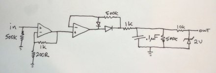
1) I added the auto power-off feature. Circuit diagram is attached. I set it for 10 minutes but that is easily changeable in the header file. The threshold for what the microcontroller considers "silence" can be easily changed. Some experimentation is necessary.
2) Faults have to persist for 200mSec to be acted on. I was getting faults from EMI when I changed the speed of my desk fan so that fixed that. I may not need that when I mount this in a chassis with a filtered power entry module.
3) I added a fault for low B+
4) I added backlight on/off switch support. If you don't connect a switch, it defaults to backlight on.
5) General code clean-up.
I will probably adapt this for a push-pull amp at some point. I'm glad I got the silence detection circuit designed/tested since that will be necessary for a class AB amp. I will want to take measurements for bias changes when there is no signal present (or at least at very low signal levels) since the tube waveform is so asymmetric and average large signal current values are not what I want to sample.
Attachments
- Home
- Amplifiers
- Tubes / Valves
- Arduino-Based Tube Amp Control System