I purchased these German line output transformers some time ago, they are marked 019.1 and come from a broadcast mixer comissioned by the RFZ (the East-Germany BBC. Well known for their lovely preamps, I purchased these for some pres I have from these old mixers.
I assume these are matching transformers, but Its impossible to find a diagram and I mysef have never wired/tested a transformer.
Any help in wiring this would be much appreciated! It would go from the preamps unbalanced output into the trafo and out to the XLR mounted on the chassis.
Thanks a bunch!
-- MusicWorks
Yes, I have a nice DVM by the same maker of the high end ones. It is an Amprobe. It is indeed quite precise, would this do?
What I dont really get is where does each wire go in terms of the XLR connection, ai need to tap the signal before the trafo for the + and the output at the other winding would be -? And where do I connect ground?
Thanks!
What I dont really get is where does each wire go in terms of the XLR connection, ai need to tap the signal before the trafo for the + and the output at the other winding would be -? And where do I connect ground?
Thanks!
set the meter to low ohms, find your two windings and the resistance for these windings.
I would have to see if I can look up the Haufe part number on the transformer.
since you are connecting to an unbalanced output with this transformer you connect the primary to your unbalanced output and the secondary is the output with one on pin 2 and the other on pin3 pin 1 would stay unconnected as the next device is the shield.
If I remember, this is a 300 ohm to 300 ohm transformer and a better transformer can be sourced for your application. These are mid to low end transformers in pro audio gear, So expect bass roll offs from 50-100 hz down. and lower bandwidths.
Try asking for help here
https://jacobkorn.de/news/vintage-rfz-preamp-racking.html
https://jacobkorn.de/news/vintage-rfz-preamp-racking.html
Many thanks for the info Andreas!!!
It was sold to me as a line output transformer, I thought, from RFZ. My lovely fully-restored BR25 loudspeakers are indeed from Gethain.
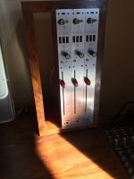
A pity, but they are useless for my application, as I need an line output transformer for my KV80/1 pres that come from an MP4084 mixer -this time I am certain- comissioned by RFZ.
See picture attached, must be small to fit in my custom made wooden box:
It was sold to me as a line output transformer, I thought, from RFZ. My lovely fully-restored BR25 loudspeakers are indeed from Gethain.
A pity, but they are useless for my application, as I need an line output transformer for my KV80/1 pres that come from an MP4084 mixer -this time I am certain- comissioned by RFZ.
See picture attached, must be small to fit in my custom made wooden box:
Attachments
RFZ is the east Germany version of Siemens and a lot of the designs are almost the same.Many thanks for the info Andreas!!!
It was sold to me as a line output transformer, I thought, from RFZ. My lovely fully-restored BR25 loudspeakers are indeed from Gethain.
A pity, but they are useless for my application, as I need an line output transformer for my KV80/1 pres that come from an MP4084 mixer -this time I am certain- comissioned by RFZ.
See picture attached, must be small to fit in my custom made wooden box:
like its similar to a Siemens 811403 PC board
This one looks more like the PV46 circuit.
Last edited:
But what is the output circuit?The RFZ amplifiers usually only have a transformer at the output of the console. You can use a common 1:1 transformer for this. In the KSG625 this is a 1:2 transformer due to the low level in the console.
I would just study the circuit and apply the appropriate transformer, and not chase around for a vintage transformer that is not going to be any better than a new one.
no problem.Here is the original data sheet, complete with diagrams and the full schematic in PDF.
Any help reading this information to choose the right output trafo is much appreciated indeed!
It will give me something to do while I work tonight on my light stadium sound job connecting a local radio station's laptop and giving the DJ a wireless mic. Once I dial that in with processing 3 minutes later, I just sit there monitoring everything.
Lol! Great, thanks!!
For some reason the schematic is a bit blurred out, I had to print it out and use a felt tip pen to outline everything so I could read it more easily (had to figure out all the pinouts).
The KV80/1 is basically a 2-stage microphone and line preamplifier with 48V for phantom power and a low cut filter. It has two inputs: E1 that is balanced and goes through the input trafo (where the magic happens!) and E2 that usually remains unused as it goes straight into the second preamp stage and adds nothing really.
The output from the first stage (A1) is connected to E3 (the input to the second preamp stage) in Pin 7. When I first wired these pres I used A1 as the main out and left the second preamplifier stage out. Recently, I have changed my mind and will use the whole strip as it was intended to (these Telefunken engineers probably knew what they were doing in terms of overall gain staging within the pre).
These offer incredible gain, when wiring it properly its insane...at first I though too much for going straight into DAW. This is the reason why I was using only the preamp stage. They have great presence and punch, some people have compared the KV80/1 favourably with Neves (!).
The is a trim pot that allows for calibration at the final stage, when everything is setup and trafo installed I will use my Neutrik Minirator tone generator to properly calibrate m. This is a +6dbU design, and this is the original factory calibration.
The 48V phantom implementation is quite unique as well, as it is derived from a +100V DC line through a zener diode circuit. Powerful phantom!!!")
The RFZ (Rundfunk zentralamt) is the equivalent of the east german BBC. Many of its designed where comissioned to Telefunken/Siemens engineers (check out classic Telefunken schematics of that era like the V762, they are made in the same style and format).
These are getting harder to find, and as other options are reaching impossible prices people are starting to be aware of their potential!!!
For some reason the schematic is a bit blurred out, I had to print it out and use a felt tip pen to outline everything so I could read it more easily (had to figure out all the pinouts).
The KV80/1 is basically a 2-stage microphone and line preamplifier with 48V for phantom power and a low cut filter. It has two inputs: E1 that is balanced and goes through the input trafo (where the magic happens!) and E2 that usually remains unused as it goes straight into the second preamp stage and adds nothing really.
The output from the first stage (A1) is connected to E3 (the input to the second preamp stage) in Pin 7. When I first wired these pres I used A1 as the main out and left the second preamplifier stage out. Recently, I have changed my mind and will use the whole strip as it was intended to (these Telefunken engineers probably knew what they were doing in terms of overall gain staging within the pre).
These offer incredible gain, when wiring it properly its insane...at first I though too much for going straight into DAW. This is the reason why I was using only the preamp stage. They have great presence and punch, some people have compared the KV80/1 favourably with Neves (!).
The is a trim pot that allows for calibration at the final stage, when everything is setup and trafo installed I will use my Neutrik Minirator tone generator to properly calibrate m. This is a +6dbU design, and this is the original factory calibration.
The 48V phantom implementation is quite unique as well, as it is derived from a +100V DC line through a zener diode circuit. Powerful phantom!!!
The RFZ (Rundfunk zentralamt) is the equivalent of the east german BBC. Many of its designed where comissioned to Telefunken/Siemens engineers (check out classic Telefunken schematics of that era like the V762, they are made in the same style and format).
These are getting harder to find, and as other options are reaching impossible prices people are starting to be aware of their potential!!!
I calculate its a 45 ohm transformer, but I would go for a good output transformer because I don't know a good source for German transformers. I would put in a Carnhill VTB1148 and wire it as a 50 ohm primary. and come up with the appropriate H-pad and match the scaling. Because you need to load it then capture it off the load from an attenuator. That a way you can drive into it and have better range on the controls since you want to record the whole channel strip. I would also try 200 ohm setting on the primary of the VTB1148 because that would give you better loading and lower noise floor.
I had a bunch of TAB/Telefunken equipment. Its ok. but their i/o standards are not really that compatible with new equipment. I have some CAPI stuff i'm building, but I'm not using 600 ohm anymore. Because that was a forced convention. 750 -1K would be more universal now these days.
I had a bunch of TAB/Telefunken equipment. Its ok. but their i/o standards are not really that compatible with new equipment. I have some CAPI stuff i'm building, but I'm not using 600 ohm anymore. Because that was a forced convention. 750 -1K would be more universal now these days.
Yes! A DVM magnetizes the core of input transformer. DC must be avoided.What test equipment do you have? A L meter to check for continuity to identify the windings? (a normal DVM could magnetize the core???) Then apply some small signal to one winding and measure the other (looks to be 2 windings only - 4 wires).
Also high input voltages at these input transformers must be avoided. Max. input voltage iof these input transformer is 1,55 Volts ->+6dB.
Best regards!
MusiKelectronic wasn´t a part of the RFZ -> Rundfunk- und Fernsehtechnisches Zentralamt der DDR.View attachment 1243921 Hi,
I purchased these German line output transformers some time ago, they are marked 019.1 and come from a broadcast mixer comissioned by the RFZ (the East-Germany BBC. Well known for their lovely preamps, I purchased these for some pres I have from these old mixers.
I assume these are matching transformers, but Its impossible to find a diagram and I mysef have never wired/tested a transformer.
Any help in wiring this would be much appreciated! It would go from the preamps unbalanced output into the trafo and out to the XLR mounted on the chassis.
Thanks a bunch!
-- MusicWorks
If you are interested in the RFZ look here: https://www.audiomodellierer.de/Home_-_Rundfunk-_und_Fernsehtechnisches_Zentralamt_der_DDR.html.
The input transformers of the KV 800, KV 80 and KV 80/1 are totally different to this item.
Best regards
I talked to a lot of members of the RFZ. They don´t work together with Siemens or Telefunken.Lol! Great, thanks!!
For some reason the schematic is a bit blurred out, I had to print it out and use a felt tip pen to outline everything so I could read it more easily (had to figure out all the pinouts).
The KV80/1 is basically a 2-stage microphone and line preamplifier with 48V for phantom power and a low cut filter. It has two inputs: E1 that is balanced and goes through the input trafo (where the magic happens!) and E2 that usually remains unused as it goes straight into the second preamp stage and adds nothing really.
The output from the first stage (A1) is connected to E3 (the input to the second preamp stage) in Pin 7. When I first wired these pres I used A1 as the main out and left the second preamplifier stage out. Recently, I have changed my mind and will use the whole strip as it was intended to (these Telefunken engineers probably knew what they were doing in terms of overall gain staging within the pre).
These offer incredible gain, when wiring it properly its insane...at first I though too much for going straight into DAW. This is the reason why I was using only the preamp stage. They have great presence and punch, some people have compared the KV80/1 favourably with Neves (!).
The is a trim pot that allows for calibration at the final stage, when everything is setup and trafo installed I will use my Neutrik Minirator tone generator to properly calibrate m. This is a +6dbU design, and this is the original factory calibration.
The 48V phantom implementation is quite unique as well, as it is derived from a +100V DC line through a zener diode circuit. Powerful phantom!!!
The RFZ (Rundfunk zentralamt) is the equivalent of the east german BBC. Many of its designed where comissioned to Telefunken/Siemens engineers (check out classic Telefunken schematics of that era like the V762, they are made in the same style and format).
These are getting harder to find, and as other options are reaching impossible prices people are starting to be aware of their potential!!!
These engineers developed their own circuits. A very good example is the V741c, which was equipped with completely different and relatively normal components. The V781 is also a completely different development than the amplifiers from Siemens or Telefunken. To my knowledge, these companies did not offer stereo preamps in a housing. The V781, for example, also uses discrete operational amplifiers. Only the latest versions uses a IC at the output amp.
The KV 800, KV 80 and KV 80/1 have the same topology with two amps. The first amp is a 5 transistor design with a special output configuration. The second amp is a four transistor design with low impedance output.
There are some differences in phantompowering, pre-listening logic and some other minor things.
Best regards!
Last edited:
It isn´t. The design of all RFZ are totally different to the design of the Leitungsverstärker PV 46 SD.RFZ is the east Germany version of Siemens and a lot of the designs are almost the same.
like its similar to a Siemens 811403 PC board
This one looks more like the PV46 circuit.
View attachment 1244893
At my website https://www.audiomodellierer.de/Home_-_Rundfunk-_und_Fernsehtechnisches_Zentralamt_der_DDR.html you can find a lot material about the RFZ. You will see, that they were good enough to develop their own electronic designs.
Best regards!
Last edited:
Yes! A DVM magnetizes the core of input transformer. DC must be avoided.
Also high input voltages at these input transformers must be avoided. Max. input voltage iof these input transformer is 1,55 Volts ->+6dB.
Best regards!
So what? The core is a soft magnetic material, it will reverse magnetize as soon as the DC source is off. I find that statement overinflated and never had problems with applying DC to high permeability nickel. I even did execute a test on a permalloy core by deliberately oversaturating it with DC, it did not lose permeability or whatever.
- Home
- Amplifiers
- Tubes / Valves
- Help wiring these German transformers