Douk Audio U2 PRO I2S - Disable 5V USB-Power

Hi

for all of you using a Douk Audio U2 PRO:
Here's a simple and fast modification to get rid of the +5V line from PC-USB when using (highly recommended) an external PSU.
I have found it on "sixmoons", so:
https://6moons.com/audioreviews/elijah/2.html >> "5 Minute Isolate CU Compatibility Test" picture
I use a very thin transparent scotch tape.
My Laptop still recognizes the U2 when I plug in the PSU.
May be other/newer PC will not but give it a try.

Kind regards

Subwoofer Input Gain, Too High?

Hello,

I have a Focal subwoofer that I modifed a little and got repaired the electronics (new transistors, recaps etc). I am using it in my home cinema setup. The sound going to the mains, surrounds and the center is full range. I use the sub specifically for the area between 30-50hz. I did this by filtering the LFE signal coming from my AVR with a graphic equalizer. The measurements look good and the response is flat. I am really pleased with what I hear.

The problem I am having is that it is one of those only auto on/off subs (bad design), so no "always on" option. As a result, I have to keep the input gain pretty high to keep it "always on": +6 from the AVR and +20-24 db from the graphic eq. It seems to work fine but I was wondering if I could damage the LFE input of my subwoofer.

Thanks in advance!

Has anyone messed with side baffles to extend bass response?

I've restored a couple of Acoustic 807 loudspeaker for use with keyboards:

ED118716-B49E-495C-8045-2D95A79C849C_1_105_c.jpeg


The low end comes from a pair of 12" drivers mounted behind a not-exactly-Bessel-curve horn structure and the backs of those drivers communicate with the port at the bottom.

As you might expect, these cabinets don't have much to give you below ~120Hz and whereas I'm running them with a one-third-octave EQ in the signal path, I'm concerned about just trying to compensate with amp power. It has been suggested to me that one way to get roughly an extra octave of bass would be to push the two cabs side-by-side to increase the width of the aperture but I was wondering if perhaps there were another (small-a) acoustic approach.

I've noticed that some models of Altec-Lansing Voice Of The Theater cabs have flat baffles that extend out to the left and right. Do any of you have experience with adding side baffles to extend bass response? I'm envisioning free-standing panels about 12"-14" wide, cut on top at a slant with the lower side adjacent to the cabinets about where the blue panel is. They could sit flat with the front of the cabs, angled so as to extend the angle of the cabs' horn structures, or somewhere in between that and flat to make the overall shape more of a crude Bessel approximation.

Attachments

  • 772999F1-9D55-44FD-A974-353552D56269_1_105_c.jpeg
    772999F1-9D55-44FD-A974-353552D56269_1_105_c.jpeg
    222.8 KB · Views: 144

PL4000.1D no audio output

I got a Planet Audio 4000.1D that had the power supply burnt but replaced all the 3205 and all 47ohm resistors and 4 of the smoothing Caps next to the speaker connection and all is good to go.


All the output FETS were good. Tested with Oscilloscope and everything is working.
Power at idle is 1.280v
All FETS are running warm not hot.
Turned all pots and switches back and forth over 100 times with no change to audio output.
Made sure my audio input and speaker worked.
Tested all transistors and Diodes on-board with multimeter set on Diode and to the best of my knowledge they all checked good.
Tested the 3w resistors on-board R25 and R26 but had Caps so couldn't get a reading. Lifted one leg and tested well.

I only have less than a year of repairing car amplifiers and can fix most but these with power and output working 100% but no audio output gives me the most trouble. I read Perry Babin Tutorial but he has so much info it's hard to remember it all. I think I just need to read it from start to finish 3 or 4 times.

Any help would be appreciated.
Thanks


20240604_104848.jpg
20240604_104853.jpg
20240604_104856.jpg

Handheld Console Amp

Hi All!
I'm incorporating an amplifier into a handheld console I've been developing. I'm trying to keep things simple as the rest of the board has been complex so trying to avoid the need for GPIO to talk to the amp. It takes the PWM signals from a raspberry Pi CM4 through the following driver buffer:
1717701187316.png

Rather than the audio jack I then intend to run the signals through an amplifier (something like a TPA2012D2):
1717701600967.png
The idea is I would then take the outputs to drive two onboard speakers but then when I plug in headphones to an audio jack this is rerouted into the headphones. This can be achieved using a headphone jack like the one in this image:
1717701380947.png

The problem is the outputs from the amp are L+, L-, R+, R- so I'm guessing I need to use some form of op-amp configuration to convert this to a single-ended output. Then I can achieve the above since it will work for the headphones and the drivers.
Am I on the right lines here? Is this a stupid way of doing things? I'm fairly good with PCB layouts and Arduino stuff but for whatever reason when it comes to Pi's and amps that talk over I2C to set everything up my brain switches off.

Taming screaming piezos. Any quick & dirty tips?

I scrapped a pair of Eltax floorstanders. Got good money for the dome tweeters. The cabinet is fairly robust so I threw in some drivers I had lying around. The Sony woofers sound okay (possibly better than the originals).
The $3 piezo bullet tweeters sound like exactly what they are - cheap and nasty.
I think the crossover point is 2.7khz.
Piezo inductance is all Greek to me. Anything I can do negate the lower HF screaming?
I'm not going to spend any money. These boxes will spend the summer in the garden pumping out tunes for our barbecues. When the weather turns cold - they are done.

peizo.jpg

Pass World standard 10uf xxVDC electrolytic coupling/isolation caps

I'm putting together a couple of Fullrange Eq boards and am needing four output caps that fit in the thread title category. I have a few choices on hand. I used Elna Silmic II caps on the first board I assembled last year, and the filters have performed very will for me. These caps were purchased in 2016 or 2017, but I understand that the quality changed a bit and that they are now discontinued. I'm robbing other projects to use the ones I have (not a huge issue for me), but I'm wondering what current production caps suited to this general use are the good choices? Not in the boutique weeds $$$.

A related question: The suggested spec (post 62 in the FR EQ thread) for the Fullrange EQ calls for a VDC of 24 for the electrolytics, but it looks like the output cap could be fine at 16VDC rating with the hot side in between the buffer jfets. Is this safe?

Thanks,

Skip

Is buffering inputs in a preamp really needed?

Hi ! looking at the schematic of some great measuring solid state line preamps i see that some have buffers just after the inputs before the attenuator
Nevertheless other preamps that shows great performance do not have buffered inputs and the signal goes directly to the volume pot
I wonder if a low ohm value attenuator could make inputs buffering avoidable
And in this case how low a pot can go ? 5kohm ? 2kohm ?
Is the rule of the ratio 10 between the input impedance of the preamp and the output impedance of the source always valid?
Thank you all for any kind and valuable advice
Good day

WTB Elna Silmic II RFS (Made in Japan) 47-220 uf low voltage

Hi, I am interested to buy some old Elna Silmic II RFS made in Japan version (deep brown jacket with gold stripe, not the regular one brown with white stripe made in Thailand).

33-330uf
low voltage, lets say up to 50V

Also if anyone has this custom made ELNA ARSA (alpha gold) series with gold leads, special vibration resistant jacket - I am also interested.
I need them for coupling purpose.
I am based in EU

4th Order High-Pass for Full Range drivers & Active Sub

I’m back at the small single driver thing again after playing with electrostatic headphones for several years. I want a sub-sat system with one or two REL T/Zero MkIII subs or a single T/5X. I was thinking of high passing the sats with a cap at 100Hz. is that enough protection for them? The REL‘s crossover maxes out at 120Hz. Any acoustical reason to go to 4th order?

Thanks, as always.

iLoud MTM Tweeter Repair - It was going well until THIS HAPPENED!

Anybody know where to get a replacement tweeter for the iLoud MTM?

I bought this speaker used but it was working well. I measured the frequency response as below:

1709224937421.png


After some general use I measured it again and now it measures with some big dips in the response. I did not play it loud.

(Below 100Hz not very accurate, but the dips in the midrange response are confirmed to be from the speaker.)

1709225024614.png


I disconnected each driver and measured them separately. I also measured the Amp outputs directly to see if maybe the filters were messed up. I guess this is correct.

1709225119285.png


So I decided the tweeter was damaged. I thought maybe it used ferrofluid and needed a refresh.

I removed the glue around the tweeter and took it out.
20240229_160033.jpg

20240229_161515.jpg

20240229_161532.jpg


Ahh.. looks like the front can not come off without a careful operation.

Bingo, we have ferroffluid!

20240229_162303.jpg


Eww... it's somehow been mopped up by the sponge. What is ferrofluid doing out of the gap?!


20240229_162610.jpg


But OH NO! I was trying to be so gentle but this happended.

20240229_163638.jpg

Hello from Peterborough, Canada. Vintage analog

Glad to have been referred to this forum.
My interest is in vintage audio equipment. i like to experiment and have purchased a fair bit of used equipment over the years, often repairing items, incorporating them into my set up and ultimately changing out pieces.

During this time i have come across some oddballs/anomalies that i may require assistance with, hence my interest in this site and i thank you for this resource.

My ER Audio Acorn Mk II build

Ever since getting my old (old as in manufactured in the 70's) Quad ESLs (the '57) to work properly, which involved augmenting them with a pair of really good super tweeters, a pair of very fast subwoofers, and a pair of OTL (OCL actually) power amps, I realized that electrostatics are what I really enjoy. I also listened to big Sound Labs on several occasions and reckoned that true full range electrostatics would and should be the next step. However new big Sound Labs are outside of my budget and used ones are next to impossible to find where I live. Even if I luck on a used pair, chances are they would need a full restoration, which is a really tough task.

In late 2020 I found ER Audio whilst looking for Quad ESL restoration materials. After some email exchanges with Rob (Rob Mackinlay, owner of ER Audio) and ordering a repair kit for the Quads, I noticed that the Acorn, ER Audio's ESL speaker kit, was now in its Mk II incarnation. Reading through the technical descriptions of the Acorn, I found many design elements that I liked. The Acorn is a three-way (4-way actually, because it has a super tweeter on the tweeter diaphragm, crossed over with surface mount components on the panel) design with separate bass and mid/treble panels, much like the '57, whereas the ESL IV, another ESL kit of ER Audio's, is similar to the ESL63 in that the whole speaker plays full range, with the signal going through some low-pass filters towards the upper and lower ends. Personally I've always preferred what I heard from the '57 than the '63.

So ordering a repair kit for the '57 ended up leading to my purchase of an Acorn Mk II kit with pre-built panels. On one hand I felt really happy because a pair of true full range electrostatics is something I've dreamt about for years; On the other hand I was secretly doubting if it was too good to be true, especially considering the price even as a kit.

My '57s were sounding nicer and nicer as I modified the OTL amps driving them (a pair of Merz Type T with 6336 output tubes) and I got really busy at work, as a result the Acorn project was put off for two years. In the beginning of this year I happened on a thread on an Aussie forum about the Acorn Mk II, and the author is none other than Gary Jacobson, owner/creator of quadesl.org! It so happened that at the same time my '57s started to develop issues again--Time to start working on the Acorn!

The Acorn is a kit sans the frames and bases, which the user will have to build themselves. So what I plan to share in this thread is mainly the design and build plan of my frame/base for the Acorn and also updates as I implement changes (will take a few posts, perhaps over a couple months, due to lack of spare time on my part--my apology first), in the hope that it would be of some help to anyone interested in building the Acorn. If you're interested in reliable assessment of the Acorn's sonic performance, Mr. Jacobson described its sonic traits very clearly in the aforementioned thread, which I highly recommend checking out.


First some pictures.

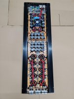
Acorn Mk II in my listening/living room (back damping is still being experimented and not in place yet):

Acorn in living room.jpg


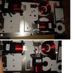
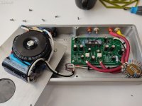
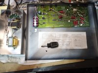
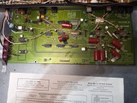
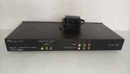
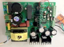
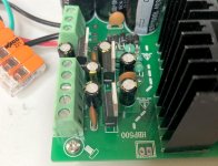
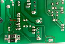
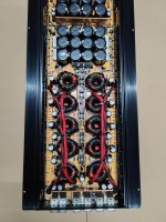
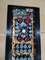
The transformers and PCB sitting on the acrylic base behind the panels:

Acorn xformers and PCB.jpg


Front of the (upper) panels. This is the left channel and the bass panel is on the left side.

Acorn panel close up.jpg

HP 8903a AC voltage measurement problem

I just got a 8903a. Initial inspection showed that AC voltage measurement in the "mV" section is far off: e.g. 100mV AC input shows 17mV on display. Upon start-up, unit is in "V" measurement range and display data shows correct input voltage (e.g. 1V AC input shows correct 1.000 on display). Reducing input voltage from there below 200mV causes the unit to switch to "mV" range and displayed voltage is completely off the chart (see above, e.g. 17mV displayed for 100mV input). Frequency display is correct in all modes. If input voltage is increased again from below 200 mV AC (e.g. back to 1V AC) unit does not switch from "mV" range to "V" range and shows wrong voltage ("0.150"). Powering off the unit and powering back on resets to "V" range and voltages above 200mV AC are displayed correct.

Can somebody provide me with directions where to start my investigation.
I have the manual but I thought before I dig into the service details I'd ask if someone experienced this issue before.

Any feedback is appreciated! Thanks

Glassware PS Tube HELP

Hello all, first time posting on the forum, and looking for some help please.

Trying to be quick here, I am not much of an electronics guy, just build amp and preamp kits in the past, kits with instructions, parts and values all lined out. I have always had good results, I follow directions well and try to have good workmanship and safety habits.

Ok, I purchased a PS Tube power supply and a pair of Aikido mono octal boards from Glassware Audio, I have only heard great things about the Aikido! I may be out over my skis here a little.

The first problem I'm having is with the PS Tube power supply, I used the recommended transformer, Hammond 6K56VG, 270-0-270 volt. I followed the directions to the best of my ability, everything seems fine, no blown fuses, nothing smoked lol, the heater voltage is spot on, but am getting 420 vdc at the B+ pad on the board. I have not attached the mono boards to the power supply, so there is no load on the power supply board. I have only left the power on for a minute or two because the 420 vdc seems really high to me, I expected somewhere around 280 vdc. It seems like a lot of transformer, but that is the one Mr. Broskie recommended to me.

I am curious if anyone has used this power supply before, and if so, could you please give me some guidance?

Thanks

Attachments

  • PS-Tube.png
    PS-Tube.png
    24 KB · Views: 177

Measuring power of class AB amplifier

Rule of thump says that one pair of transistors may produce about 60W at 8R load if powered between 35-40 V rails in class AB operation .
And will do that while moving in a SOA more or less .
Based on this you can make a very rough calculation looking at the number of transistors .
So i am in a conversration with a car audio guy , looking at a product that is working at class AB , single rails not class G or H , with THAT number of transistors , and with THAT rail voltage ....
I make the calculation based on the rule of thump and say to him that you do expect this machine to produce THAT watt @8R more ore less double at 4R given that no VI limmiter exists rails are low ( lower than the rule ) and given that power supply is enough for that .
Then the argument starts .....
he said a number in Watts that was almost 3 time the numer i said ...
WTF i said and how come you can say that ?
do you have scopes generators and dummy reactive loads to measure that ????
HE looks at me surprised and said
This is not the way to measure amplifers !!!
i am about to get a stroke and said ok .... what is the method ???
Only thing you need to know is OHMS law
use of one multimer
Calculate volts times amps over the load and you have the Watts ....
left the conversation gone for harakiri

For Sale Morel Supreme tweeter ST 728 / Italy

Selected pair of Supreme tweeters, 8ohm, neodymium, 72mm flange. Very little used on a decommissioned project. Speakers like new sonically superb. Euro 350,00. Thank you for your attention

SOLD

Attachments

  • IMG_1623.jpeg
    IMG_1623.jpeg
    758.7 KB · Views: 71
  • IMG_1622.jpeg
    IMG_1622.jpeg
    487.4 KB · Views: 70
  • IMG_1624.jpeg
    IMG_1624.jpeg
    391.5 KB · Views: 65
  • IMG_1625.jpeg
    IMG_1625.jpeg
    437.5 KB · Views: 67
  • IMG_1627.jpeg
    IMG_1627.jpeg
    371.4 KB · Views: 63

Crossover formula question. What does this "q-ish" symbol mean?

I am interested in playing around with this 4 way crossover from tubecad.com but I got stuck on a formula.

1000006912.jpg

To calculate the parts values he gives the following formulas:
1000006911.jpg

I get how to calculate the capacitor values. But what is the "q" looking symbol in the formulas for calculation of the inductor values?

Here is the whole article: https://www.tubecad.com/2017/11/blog0403.htm

Thanks!

The best microphone position for recording

I’d like to record a video clip of my audio system playing musics and share to my friends via Facebook. The recorder is simply an iPhone (model XR). I wonder to achieve the best records; sound closest to the real listening in front of the speakers (to allow my friends to hear my system’s sound, not the music), and have minimum room effected sound, what position is the best? Should it be a meter away from the front of the speaker plane and height to tweeter’s level? Currently, I locate the microphone (the iPhone) so that the left and right speakers stay at the edges of the mobile phone’s display and the height is about center between two woofers due to the limited height of the stand, my speakers are floor-standing Braun LS200.

PS. I know it’s difficult to achieve the best sounding, but the objective is to let my friends listen to mine and we comment each other. It’s just for fun activity.

Tweeter modifications

Specifically drilling out the pole piece.
I've never drilled out a pole piece before, although I have once tried to do this on a Realistic dome midrange.
I've had these tweeters on the shelf almost forever [ Dick Smith sell-out almost 25 years ago] and while they are OK as-is; I'd like to see if I can drop the Fs down a bit from 1100hz.
I've got a 6mm Cobalt drill bit waiting but I'm wondering if I should try and go bigger?
I'm also wondering how best to do the rear damping and the easiest way to fix a cup to the back; I've got some screw-top plastic lids that could be made to fit but LDPE isn't easy for me to glue. Next in line would be scrap of MDF with a hole gouged out. I did think about a small cat food tin epoxied on but I thought that adding a steel cap to the rear was probably not the best idea.
EDIT
Just wondering now if drilling all the way through is needed or if just drilling down enough to stuff some long fibre wool inside would be sufficient?

Attachments

  • IMG_2853.JPG
    IMG_2853.JPG
    66.7 KB · Views: 66
  • IMG_3007.JPG
    IMG_3007.JPG
    130.5 KB · Views: 69
  • IMG_3008.JPG
    IMG_3008.JPG
    97.3 KB · Views: 71

new member, interested in audio and bettering my audio repair skills

Hi all, my name is Trevor. I have been doing audio repair here and there for years now but lately I have been tackling more amplifier related projects which I find much more difficult than other types of audio. As such I am trying to broaden my knowledge on such repairs as much as possible. I generally like late 70s to early 90s Japanese solid state (and adjacent) but I have owned quite a bit of stuff over the years.

Which Class-D amp to get from Aliexpress?

Hello Folks!

So, I have moved to the UK and only have the DAC (Topping NX4 DSD) with me now. Have to source a pair of bookshelf speakers and a decent amp with maybe a Bluetooth input option apart from the 3.5mm input?

I know a lot has changed from the Aiyima class-D amp I got like 4 years year ago. That amp was decent though.
I'm sure there would be a ton of amps now that this stuff is getting better in China.

The budget is like $60 - $90. Bluetooth input would be great as well as the 4 Ohm capability. Yeah, I can increase the budget but it would eat into the speaker budget.

Also, I don't have any DIY electronics tools like multi-meter, soldering iron and things like that. Couldn't risk it with the airlines.
Do you think buying it from Aliexpress is worth the hassle?

Thank you!

Who did it?

Was given MSB link DAC with that dreaded PCM1716 dac. Plugged in the home brew can hosting PSU . No light on the faceplate. Bummer ! . Took the hood off and here it goes. The cable connecting to display were nowhere to be found. I guess detrimental to SQ. Pretty heavy stuff going on on the board circa vintage 00 era . Elna Stargate on PSU , Cerafines and even two red BG's , Caddock and Vishay precision resistors. Actually pretty smooth sound. I thought that I will sell it and spend the money on booze and women but I guess I'm stuck with it. That PCM1716 has an abysmal opinion but the sound isn't half bad actually

Attachments

  • 20240605_201601.jpg
    20240605_201601.jpg
    482.5 KB · Views: 102
  • 20240605_201610.jpg
    20240605_201610.jpg
    681.9 KB · Views: 103
  • 20240605_201621.jpg
    20240605_201621.jpg
    486.9 KB · Views: 95

jjasniew's Guitar Amp from Bogen M330A Husk

I luckily picked up one of these at the local Ham Radio swap meet. I'm going to turn it into a guitar amp / experimentation platform, to try out some ideas I've had. It will not be a "get a fender schematic and go for it" type build. An additional bit of luck, the amp came up on the Variac with no red plating of the 7868 output tubes and connecting a speaker, I've confirmed a signal makes it through.

Here's what the amp looks like with the cover off;

Bogen.png


I gutted the whole thing, leaving only the output stage intact. Bought two new sockets, salvaged one from the mic transformer position. I was hoping to use at least some of the original circuits, but after wrestling several crimped wire leads off socket pins, I decided on a clean sweep.

1711746898463.png


Even testing my filament connections - smoke! How could this be? Turns out one wire at the upper left corner of the black socket possibly was touching a ground tab provided by that socket. Dont know why that would short circuit the heater winding...looking at the terminals where the PT heater winding attaches, neither are grounded. I ended up replacing the TWP from the power tube sockets and now all 5 tubes light. The original TWP was in bad shape; the short may have been there in a breached jacket in the first place. Nice way to beat up my PT, right out of the chute. Hopefully, this incident isnt foretelling of how things are going to go with my project.

I'm going to start completely **s backward, by making the phase splitter be the very first tube. Dual pots for all controls isnt economical, but this isnt a production design. From what I'm reading, using a 12AX7 as this first tube, LTP with a current sink, I need a small negative voltage somehow at a small current. I realize I cant steal it from the existing -20V output tube bias supply, because, there's current and that would make that voltage not be -20 anymore.

Hopefully, my next post will show a solution and the first stage built from input jack to two, 180 deg out of phase signals, coming from a dual pot which I'd label "Pre". Thanks for watching, be sure to click "subscribe" ;')
  • Like
Reactions: sahazel

Pioneer SX5580 Tuner issues

Hi,

My old Pioneer receiver has developed an issue with its tuner after many years service. A static, crackling noise is now audible on FM only. The amp behaves perfectly on all other inputs.

The noise is very obvious on spoken word broadcasts although with the muting on there is no noise in between stations just silence until the tuner is tuned to a broadcast.

The protection circuit board required all the electrolytics replacing last year and maybe the tuner circuit board now needs the same upgrade or is there anything else to investigate first ? The part number is aws067.

Would it be simpler to change the complete tuner circuit board from a known good unit rather than all the many capacitors ?

Any advice welcome.

David.

Ultracapacitor questions?

Hey guys I got an Ultracapacitor from Ian Canada and wanted to ask a few questions from people more knowledgeable than me.

I got it to put on my Ifi Zen Can Sig.

yes the bass increased but the definition degraded and the bass seems a bit too much.

is there something I’m doing wrong?

do I need to unplug the SMPS when using the Zen Can and just feed power from the Ultracapacitor?

thanks in advance !

Phono-Stage Hiss

I built a phono-stage as shown in the schematic. This was the second one I built after loving the first one I built. Completely silent and then after about 2 months and a hundred hours or so of play, a hiss developed in the left channel. It sounded like "tube rush" but swapping out the tubes did not change the hiss. There occasionally is a little "rustle" along with the hiss but the sound is mostly smooth. It is not audible during playback but it is there between songs.
1) swapped the tubes side to side - no change - hiss on the left still.
2) switched to another preamp input - all quiet
3) swapped leads from phono to preamp R to L - hiss follows the output of the left channel
4) swapped leads from SUT to phono R to L - hiss remains on left
5) shorted phono inputs - hiss still on left channel
6) switched mono/stereo switch to mono - hiss now in both channels but softer
7) tubes replaced - no change as expected
I reflowed all the solder joints without improvement. Did some jumping and finally seemed to narrow it down to the 330KΩ grid leak resistor before the second tube. I replaced both that resistor as well as the 300Ω carbon composite grid stopper and all was well until June - so about 6 months. I am about to dig back in but was hoping for some suggestions as to where to look?
The hiss is not always there and seems to appear more often when I've been listening awhile - meaning hours and fully warmed up.
I'd like to focus on troubleshooting rather than the merits of the design if possible.
Additionally, microphony seems to increase when the problem is occurring.
I feel I’ve exhausted the troubleshooting from the forum where I originally got the schematic and build help.
The tubes are heated with Pete Millett's DC filament supply. Each channel has its own supply.
Thanks in advance.

Screenshot 2023-06-27 175535.jpg

Screenshot 2023-06-27 175646.jpg

Importance of precision in volume control of a balanced signal

Hello everyone, I ask for clarification regarding the best type of potentiometer to create a volume control in a balanced line.
My doubt is above all about the degree of precision of the component, in my ignorance I imagine that while for an unbalanced line a slight misalignment in the resistance values of a stereo potentiometer does not have an appreciable influence on the signal (at most it will suffer a slight variation in level between the two channels), I fear that for a balanced line a slight misalignment between the resistive values of the two + and - poles of the same channel could negatively influence the correct reconstruction of the wave inside the amplifier, but I hope I'm wrong.
Is it therefore possible to use a normal 4-way potentiometer with 10-20% tolerance for a balanced stereo signal or is a high precision component required?
Thank you all.

TPA6102 and 600 Ohm headphones, is 2x9V batteries enough?

Greetings, first post here and mostly noob in analog electronics, so please be gentle..
So I found in an thrift store Philips N6330 (sibling of AKG K240), which are 600 Ohm headphones and need something to drive them and there's not as many options as I expected. Not ready to invest more than pocket change yet so found this TPA6120 board on aliexpress for ~7EUR which looks like it should do the trick for now, but I don't have a suitable +- 12V transformer readily available. I suspect this board has something like pair of LM7809s on it as it wants +-12V AC, but don't have any means to verify it.

So the question is, if I bypass rectifiers and connect two 9V batteries, would that be enough to drive 600 Ohm headphones, at least to see if I like their sound and buy something better?

The other option is get +12V and -12V DC from old ATX power supply, would that be a better choice?

NEW-TPA6120-Headphone-Amplifier-Board-HIFI-TPA6120A2-Audiophile-Headphone-Amplifier-Board-Zero...jpg

New member. Interested in Dynaco ST400 and ST416 info.

I'll mostly be lurking but I've got several ST400s and a ST416 I've been maintaining for a few decades and looking around to see what people are doing to make them a little nicer. My ST416 is about to get a new PC30 and filter caps from AkiTika and fresh PC28s from Fantasia since both boards are pretty cooked after 5 decades esp under the PC28 resistors that I did the 3watt metal film replacement on a few years ago and spaced them off the board but the pcboards were already pretty crispy...

Bisesik output transformers D60 for DAC

Selling 1x pair of Bisesik output transformers for DAC (PCM56, PCM63, TDA1541). They have fantastic sound. Selling due to change in DAC topology. Like new condition.

Ratio 1:10
2 parallel primaries, 1 secondary
D60 version (bigger bandwidth)

Info at: https://ivxformers.com/
Or thread: https://www.diyaudio.com/community/threads/output-transformers-for-dacs.327794/

Original price: 600USD + 21% EU VAT = 726USD

Asking price: 580USD / 520EUR (or best offer) + shipping

Will be shipped from Czech republic/EU so no VAT issues inside EU.

Attachments

  • 20240605_202331.jpg
    20240605_202331.jpg
    333.1 KB · Views: 61

Noise into bluetooth module

Hello everyone , i hope you all having a great day!

Ive been working on a audio project and i want to use a bluetooth module for that. I have the schematic posted here to have a better view. So RL is the bluetooth module ground, im using a low side switch with 2 mosfets. The problem is im getting a "bzzzz" kind of noise when using the bluetooth module and im not really sure why this is happening and what is causing this. I do have decoupling capacitors. (The second Mosfet also has a 22k resistor and capacitor in the gate but its not visible in the picture below)

Attachments

  • Χωρίς τίτλο.png
    Χωρίς τίτλο.png
    17.4 KB · Views: 82

Retool of Classic Hitachi App Note Lateral FET Amplifier

I have had some peeves with the classic Hitachi Lateral mosfet amplifer designs from the app notes in the early 80's, mainly due to the limited amount of current available from the 2nd differential stage for charging the gates of the output lateral mosfets. I sorta had my way with the original design and came up with one utilizing a Pmos input, bipolar second differential stage, and a follower stage to drive the output lateral fets. Since I don't have lateral fets in my PSpice bag of tricks, I used a Vgs multiplier for bias and a complementary vertical fet output stage. In practice, I would use a simple resistive bias scheme and lateral outputs (Exicon, anyone?). Attached are a preliminary schematic, output, and sim distortion profile.

Attachments

  • Hitachi2.gif
    Hitachi2.gif
    40.3 KB · Views: 761
  • Image1.gif
    Image1.gif
    7.1 KB · Views: 659
  • Image2.gif
    Image2.gif
    180.9 KB · Views: 665
  • Like
Reactions: mlloyd1

Buzzing in the amplifier when I touch the touchscreen of the connected cellphone.

When I connect my cell phone to my DIY guitar amplifier, I get a noticeable buzzing noise when I touch the phone's touchscreen. The phone is connected via a fairly good aux cable to transport the mp3 signal. The buzzing noise seems to be at a low frequency, and it disappears when I touch the PCB's ground or the guitar strings.

Why does this phenomenon occur and how can I solve it if it is solvable?

Even without the cell phone connected, touching the ground with my finger reduces the faint background noise. Why does this happen?

noiseless small cooling fan source

There is plethora of choices on Bay but does any of you have a positive experience with any particular fan brand/design ? I need a small unit 3"x3" max to cool down overheating old cd player. I found in my junk drawer brushless 12V /0.18A unit and hooked it up to 5V power supply inside the player and can confirm it's effectiveness but it's way too noisy. It is a pretty old unit so maybe newer designs are quieter.

Power adapter/supply for Mirage LFX-3 crossover

I need to replace the power adapter for my Mirage LFX-3 crossover.
The supplied adapter puts out 18 volts AC. However, the back of the crossover where the output of the adapter goes indicated that it takes 16 volts AC. See attached photo.
So, looking for a replacement power supply, should I look for a 18 volt AC output or a 16 volt AC output. Aside from 2 volts, what is the difference between using 18 volt or 16 volt supply? Is there a downside or an upside to using 18 volts if 16 volts is specified by design. Why? I assume that Mirage thought that 18 volts was OK (probably what was available off the shelf). But, I would prefer to do what is best rather than what is potentially just OK. I would ask Mirage, but they don't really exist.
Thanks for the help!

Attachments

  • IMG_20220914_135257-scaled.jpg
    IMG_20220914_135257-scaled.jpg
    173.3 KB · Views: 90

Scratching my Brain trying to remember a tube type...

I am trying to remember the number of a regulator triode, which is essentially half of a 6528 on a smaller base - but I can't remember if it was magnovial, 9 pin miniature or what.... it's a graphite plate tube, very similar construction to the whole family of 6as7/6336/6528....

So, I have found the 7233, but I know that's not it - as what I'm looking for has a slightly higher mu, and I remember much higher gm, like twice the 7233... like the difference between 6336 and 6528. It is to 6528 what 7233 is to 6336.... I wish I would have bought some years ago whenever I was pondering them, but it seems I did not, after rifling through my shelves a couple times over....

Anybody know what I'm on about? I'm just gonna have to go through data sheets one by one, lawd have mercy... and the thing is - it might be a soviet tube... sigh...

Full range Markaudio CHN-40 questions

So, I want to build some small full range speakers and they need to be 8ohm. I found the Mark Audio CHN-40 so I ordered a pair. They have some box designs on the product page, and I like the "Compact Mass-Loaded Horn".

When Looking at the dimensions, it looks to me like it doesn't quite work with the driver being 40mm from the inside top. This would put the chamfer behind the driver cutout partly into the face to top joint. I decided to quickly draw up the box in Fusion360 and it confirmed my suspicions. I also think it looks a bit funny way up there.

If the design is anything like the BiB box, then I would also suspect the internal baffle should be 64mm from the top, and not 40mm, which might might be a better distance down. They have a similar design for the CHN-50 and this is the case.

Any ideas on this? is this a typo on their end? I'm a decent builder, but no designer by any means.
chn-40 compact loaded horn v2.png
CHN40-Compact-Mass-Loaded-Horn.png

Any final options before dumping Shanling SCD-T200?

I have a Shanling SCD-T200 SACD player bought maybe 15-18 years ago. 5 years ago it developed the dreaded NO DISC problem and my investigation found that the servo board to fix this was not available, even though the laser is still around. It's the same laser/servo as the flagship Sony SCD1, which has the same fault.

My investigations are summarised here: https://www.diyaudio.com/community/threads/shanling-scd-t200-tube-sacd-player.362298/#post-7153259

Specifications here: https://www.usatubeaudio.com/product/digital/cd-disc-players/shanling-scd-t200/

This player was expensive, heavy and an absolute work of art. Up to now I haven't been able to bring myself to throw it out, but if it is truly unfixable then I'm just about ready to do that.

So this is a last gasp message to wonder whether there are any alternative options.
  • Is it possible to use an alternative servo board and/or CD laser mechanism, for example.
  • Any options to re-purpose the tube line-out and headphone outputs?
  • Any parts worth salvaging, e.g. High precision PGA2311 electronic volume control (100 steps with memory)
  • Anything!!??

Thanks

Attachments

  • Shanling SCD-T200.jpg
    Shanling SCD-T200.jpg
    259.4 KB · Views: 354

Apple Homepod 4.5 driver enclosure recommendation for full range

hi ...

i have a pair of apple homepod midwoofers here (one actually planned for microsub project but abandoned due to over excursion issues that cannot be avoided even running on 4th order bandpass ) ... i plan to run them ported for full range ... but seems like the original application of the apple homepod was sealed with EQ application ... any issues of using ported as full range? thanks

Attachments

  • 201117401_1664419667093886_9169881968276295622_n.jpg
    201117401_1664419667093886_9169881968276295622_n.jpg
    364.7 KB · Views: 335
  • 201319993_508175950333404_6831121662173550237_n.jpg
    201319993_508175950333404_6831121662173550237_n.jpg
    396.5 KB · Views: 344

Sharing power supply for mono block pre and power amp

I am building Pass Mono Block.

having independent power supply would be beneficial for channel separation.

I will have 2 separate Transformers for each channel, I intend to separate my preamplifier and have “integrated” mono block (I.E. pre and power amp together.)

Would sharing the same transformer for pre and power amplifier have any detrimental effect?

XA160.8 220V and 240V

Hi guys, a friend of mine own a pair of XA160.8 monoblock rated 220V, he’s soon moving to Australia(240V), are they going to work correctly with 240V? I mean they’ll definitely turn on and sing for a while at least, but some designs are sensitive with that 10% voltage increment, causing over heat or worse melting something in long run, what will happen in this case?
Thanks 🙏

wiring up the ICEedge 1200AS2 board

-Im tryiong to wire up this amp and put it in a Modushop box. in the instructions manual there is this:

48FEH0g.png


this is the channel 2 speaker output. question is. what does non inverting and inverting mean? I expect 2 leads + and -. I'd connect the + to red speaker terminal and - to black speaker terminal. but instead i have 4 leads called inverting and non inverting. what is this f%^$#ry? lol

3-way active standmounts with coax upper end & Other UniQ adventures

I have been thinking about a project a project like this for some time, so why not start a thread to get it going. The plan is to build fairly large standmount speakers using a coaxial mid-high and a 10”woofer, so quite much inspired by Genelec 8260.

pd8260a01-1024x768.jpg


Objective 1: Learning and having fun. Learn new design, simulation, and fabrication skills. Getting more experience with Ath, VituixCAD, and Fusion360. And on the fabrication side the goal is to use all the cool toys available at the Uni FabLab (3D scanning, 3D printing, laser cutting, CNC…).

Objective 2: Controlled directivity and low diffraction using waveguides and baffle shaping.

Objective 3: The result should sound in our compact living room better than my current speakers, SP38/13 by Troels Gravesen. This rather ambitions, but let’s see…


Electronics: miniDSP 4x10HD and TPA3255 amps with 4x150W and 2x300W.

Initial thoughts on driver selection: Kef Q100 drivers would be quite safe choice for this application, but they are not so easy to obtain these days. The newer Q150 model is easy to come by, but I have understood that it uses inferior drivers (stamped steel basket etc). The other alternative I have in mind is Kartesian Cox120 from TLPH. There’s not much info or experiences available for this driver though. It’s a rather small 4.5” coax but the inverted surround of the cone would allow seamless integration with an additional waveguide structure. I think I will run some simulations with Ath to find out the tweeter polar response with and without an additional waveguide. I have excluded SEAS King Coax because of the price.

There are much more good candidates for the lower end. The woofer should work in ~30 l sealed enclosure and allow crossing in the 250-400Hz in order that relieve the midcone from the bass duties. Options include SEAS L26ROY, Dayton RSS265HF, SB wo24p, SB29NRX75… I suppose this is a compromise between nice upper bass and capacity at the lower end (woofer vs subwoofer). My amps like low impedances so 4 ohm models preferred in that respect.

Edit: A pair Kef Q100 drivers was aquired for this project.

Here is a list of all coaxial drivers linked to linked to this thread:

Kartesian Cox120
Coaxial speaker Kartesian Cox120_vHP, 8 ohm, 120 mm
Kef Q100 driver SP1587 5” Uni-Q, 4 Ohm measurements
Kef Q100 Speaker Drive Unit Testing

Omnes Audio CX 3.1
Die Klangmanufaktur | Omnes Audio CX 3.1 | Lautsprecher Manufaktur
Omnes Audio Exclusive 8AL Monitor
Omnes Audio Exclusiv 3/8

Seas MR18REX/XF

Seas MR18REX/XF (H1699) 7" Midrange Coaxial: Madisound Speaker Components
DIY speaker by Juhazi

Seas L12RE/XFC
https://seas.no/index.php?option=com_content&view=article&id=106:h1602-0406-l12rexfc&catid=52&Itemid=464
Desing and crossover from Seas/Madisound:http://www.madisound.com/pdf/L12RE_XFC_AppNote.pdf
There is a commercial 2-way that uses this driver and got rave reviews in Stereophile:
Trenner & Friedl Sun loudspeaker | Stereophile.com

Sica 5.5 C 1.5 CP
Boutique Haut-parleurs & Audio DIY
DIY speaker project based on Sica coaxials: Neue-Interessante-Sica-5-5-und-6-5-Zoll-Coaxe-mit-Kalotten-HT

Tangband Q6-2313
W6-2313 - 6.5” Paper Coaxial Full Range - TB SPEAKER CO., LTD.

PAL007B / TDA7560 / TDA7388 equivalent !?.

Hi , if anyone used these ic's or knows. I need replacemenet for Pioneer MOSFET PAL007B. and maybe PAL001A.
From what I've found there is TDA7560 .
or the / TDA7388 ( pin compatible but not mosfet ) .

Please take a look at the pictures, The 3rd picture it's the TDA7560 on sale it says equivalent for PAL005.
Need a bit of help if anyone knows something.
Thank you,
- Bruno.

Attachments

  • 20240604_232811.jpg
    20240604_232811.jpg
    364.1 KB · Views: 175
  • 20240604_232807.jpg
    20240604_232807.jpg
    354.7 KB · Views: 173
  • equivalent.PNG
    equivalent.PNG
    16.1 KB · Views: 174
  • PAL001A.PNG
    PAL001A.PNG
    30.2 KB · Views: 348

Recommended phono preamp kit

Hey all,

My system is all SS these days and I think the phono pre could be a reasonable component to incorporate tubes.

In an attempt to scope the discussion, I will ask for opinions on the quality of the designs in some of the more readily available kits such as:

Or well-proven designs using 6922 or 5842 (of which I have quite a few nice NOS tubes).

Thanks !

Need Help to setup 2 Wondom Class D amps with DSP crossover

Hi Guys..
I need some help to setup 2 Wondom JAB-250 2x50 watt boards.
My plan is/was to build 2 two way speakers each with a Wondom JAB3-250 board.
One channel will be used to drive the mid/woofer till 2200 hz And other channel is for the Tweeter starting at 2200 hz..
can this be done in this way.?
I am not sure if these boards supports left and right channel to be diffrent in settings..

Kind regards Oscar

Need another tone arm with VTA on the fly

Currently using my magnepan unitrac and am looking to get a tone arm for another table. Must have VTA and preferably on the fly. Not asking for opinions
on need for it. That said, Rega is out. I know others sell add ons to accomplish this, but I want one that comes with it. I almost bought one VPI sells at 2600, then discovered you also need the tonearm base which is sold separately for additional 1500! No thanks. I see plenty that have adjustment, but not on the fly. Maybe doesnt exist any more?

Thanks,

Russellc

Why Do Tweeters Compress At The Top?

I've just watched Erin's Audio Corner review and measurments of the TAD CR1-TX.

He shows a compression measurment. At the highest levels there is a drop in output above 10KHz, but not much a the xover region. Given that excursion will be most at the lower range, why do we see compression in the tweeters top octave, but not the lower? It must be something unrelated to excusion.

Talking about passive speakers here or those without limiters.

Is it coil heating, back emf, crossover part non linearity?

Most 'Musical' pF Value Cap

I've been going a little nuts as I'm sure quite a few on here could appreciate swapping caps in the signal path of my preamp. I've had great differences with LCR Polystyrene, Amtrans PP, CDM Mica, and the ceramics which were in there. PP can be very detailed but bright, styrene smoothner but maybe not the most accurate and veiled somewhat. Interested in some of your favorites - 100pF is my value.

Giveaway PCBs and pucks for Warbler

Seems not so many specimens of this one around here. ZM tested one don’t know if he still has it and then me 🙂

Practically this is A Big Mofo on steroids.

complete amp.jpg


What about giving birth to another one? Are there any FABs left around?

I am giving away a pair of empty pcbs for the amp, a pair of empty pcbs for the power supply and a pair of ixfn280n085 pucks.

pcb.jpg


1.If you consider you are a FAB you will still need a power supply that can give 26-32v/3.5a for each channel, preferably a 36v 200w smps from meanwell for each channel. I recommend the 36v one, lrs-200-36 which can be adjusted for 32-33V on the output.
2. You will need an inductor that can support the bias current which is set between 3-3.5a so a 4a inductor preferably for each channel. I got mine very cheap from www.Ogonowski.eu
3. You will need a heatsink with a thermal resistance of 0.2C/W at maximum for each channel so a 5u deluxe enclosure for both channels or something smaller force cooled.
4. You will need also a preamp that can swing 20Vpk no matter if it’s a high output impedance valve one, the amp has a high enough input impedance to handle all of them.
5. You will need also all the parts in the BOM.
6. And last but not the least.. you are comfortable soldering smd parts.

Instead of the puck mosfet you can use as gain device a sit like thf51s or the 2sk182es.

Here are the schematics

For the amp
sch amp.jpg


And for the psu
sch psu.jpg


So if you are sure you are going to build this amp make a second thought and if still sure put your name in the list.

How it'll work:
To enter, just copy the list of entrants, paste into a new comment, add your DIYA username to the bottom of that list and post. Tuesday night I'll make a comment saying that entries are closed. I'll take the final list of entrants, paste them into an online randomizer, and the name that appears in the top (#1) position will be the winner.
Because this is a serious build and I don`t want that the boards will be stashed instead of being used, the winner will need to post some pics with one of the requested items at points 1-4. So if you have a pair of lrs-200-36 or a pair of inductors or the heatsinks or the preamp you are good to go.


Good luck!

Using different class amps for a better top end

I recently did a test running one of my class D PA amps against my hifi (cambridge audio azure power amp). This was done through my hifi speakers (focal aria 926). PA amp drove the left speaker whilst the cambridge drove the right. When sat at a distance with not great room acoustics it sounded like the same amplifier driving both speakers. But putting your head right next to the drivers and moving going back and forth between the left and right speaker there was a noticeable difference. The cambridge amp just had greater high end detail and better separation of the midrange elements. Id say the difference was comparable to testing a 500 quid integrated hifi amp versus my a mid / higher end power amp.
It got me thinking that maybe for my PA system I could move away from the high power class D amps for the top end (dual diaphram coaxial compression drivers - 700hz up) and perhaps go with a much lower powered class AB amp instead. I believe these are inherrently much cleaner at the top end than class D. I'd need a 2 channel amp per driver / stack and ideally with the ability to set rms / peak limiters via DSP.
There was one unit I found which does seem to fit the bill, the QSC XTi 1002. Has all the attributes and isnt too expensive per unit, but the question is would I be wasting my time even obtaining and trying this amp. Will it actually have a cleaner top end more on par with my hifi power amp? Or should I just get saving and go with a higher end class D amp instead ( powersoft, mc2, linear research etc). Any thoughts appreciated.

DIY Blower Fan for Projector - Need Advice

Hey everyone,

I'm looking to upgrade my cheap projector by replacing the current blower fan with a DIY blower fan to reduce the noise. My plan is to 3D print something similar to this design and use a Noctua case fan as the motor.

I have a couple of questions:

  1. Does this idea make sense from a noise perspective? Is the blower fan noisy mainly because of the motor, or are there other factors involved?
  2. If I match the RPM of the new case fan to the original blower fan, will it provide sufficient airflow?
Thanks for the help!

TEAMPIE Amplifiers! Who knows them?

Hello lads.

I ask you a question:

I am very attracted to the "Korea style" amplifiers produced by the TEAMPIE company.

Over the years I have observed them a lot, I have seen that they have produced small models, starting from 1500w up to large models that reach and exceed 7500w.

For some time now I have been following the latest model they produced, the 20k, which claims to deliver 20000w rms at 1ohm impedance.

I know they follow the design of the Korean manufacturers (zenon or S&I) but they produce it in China with their own materials, which really puzzles me.

If a Korean company like ZENON or S&I produces an amplifier with certain costs, and then sells them with a certain profit margin, how can TEAMPIE produce the same amplifier (or perhaps even better) at decidedly competitive prices?

For example, the 20k that I'm eyeing and would like to buy has the same design as the DC AUDIO PITBULL 20K (WITH 8 LESS OUTPUT MOSFETs), or the DEAF BONCE AAK20000 (WITH THE SAME NUMBER OF OUTPUT MOSFETs) and uses the same MOSFET driving system (IR2184 + DRIVERS TC4452 in FULL BRIDGE configuration).

I also received a video attesting to its delivery at 1ohm of real impedance of 22kw RMS in burp, which would demonstrate that this is a monstrous amplifier for the cost at which it is sold!

Do any of you have more precise information and can advise me?

I'm also posting a photo of the board.

Attachments

  • Immagine WhatsApp 2024-06-01 ore 12.16.44_2c309396.jpg
    Immagine WhatsApp 2024-06-01 ore 12.16.44_2c309396.jpg
    156.9 KB · Views: 175
  • Immagine WhatsApp 2024-06-01 ore 12.16.44_87cd13a4.jpg
    Immagine WhatsApp 2024-06-01 ore 12.16.44_87cd13a4.jpg
    113.4 KB · Views: 187
  • Immagine WhatsApp 2024-06-01 ore 12.16.45_ae71e1da.jpg
    Immagine WhatsApp 2024-06-01 ore 12.16.45_ae71e1da.jpg
    162.7 KB · Views: 149

B+ dropped 15%

Hi, I don’t post much but I get great info from the group. I have a DIY Don Garber/Loftin White type 2A3 amp. My previous homes AC voltage was 123VAC and the PT is 750VAC center tapped. Per Don’s schematic I was within 1% voltage was at all the the critical test points. The PT is setup for 123VAC. My new homes AC is 119VAC. With changing anything or digging into why, my voltages have dropped like 15% and starts with the B+. Where should I start investigating for the reasons. Help is very much appreciated.
Projects by fanatics, for fanatics
Get answers and advice for everyone wanting to learn the art of audio.
Join the Community
507,689
Members
7,884,372
Messages

Filter

Forum Statistics

Threads
406,048
Messages
7,884,372
Members
507,689
Latest member
Giannikos