Trying to see FFT of a typical tube gain stage
- By nauta
- Tubes / Valves
- 8 Replies
Hi
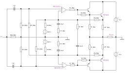
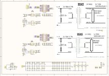
Everyone says that triode tubes have more 2nd harmonic THD than anything else and I wanted to see this in LTspice. I made a CC gain stage with typical values and ran it with a low-level sine input. The output was generally clean looking and THD was pretty typical from what I've read.
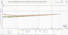
The FFT of the output showed odd and even harmonics with the 3rd not being much lower than the 2nd. A few higher harmonics were present in both FFTs. I know the curve for a triode follows a 2/3 exponent, which maybe does produce both even and odd harmonics?
I wondered what the input signal looked like and its FFT was similar AND its THD baseline was only a little below the baseline for the output FFT. This made me wonder if the tube was simply amplifying the dirty oscillator harmonics?
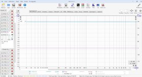
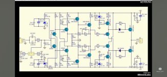
I went to a different file for a super-low-THD solid-state amp and checked its input and output FFT. In this case, the baseline for the output FFT was around -180dB and 10dB lower for the input.
So, it seems like LTspice scales the THD of the sine generator depending on the range of THD the circuit under test generates?
Does this seem normal?
Thanks
Everyone says that triode tubes have more 2nd harmonic THD than anything else and I wanted to see this in LTspice. I made a CC gain stage with typical values and ran it with a low-level sine input. The output was generally clean looking and THD was pretty typical from what I've read.
The FFT of the output showed odd and even harmonics with the 3rd not being much lower than the 2nd. A few higher harmonics were present in both FFTs. I know the curve for a triode follows a 2/3 exponent, which maybe does produce both even and odd harmonics?
I wondered what the input signal looked like and its FFT was similar AND its THD baseline was only a little below the baseline for the output FFT. This made me wonder if the tube was simply amplifying the dirty oscillator harmonics?
I went to a different file for a super-low-THD solid-state amp and checked its input and output FFT. In this case, the baseline for the output FFT was around -180dB and 10dB lower for the input.
So, it seems like LTspice scales the THD of the sine generator depending on the range of THD the circuit under test generates?
Does this seem normal?
Thanks