Hello
I planned to build a budget 5 inch bookshelf speaker (either classic 2 way, MTM or TMM) for learning purpose (I don't dare to start with expensive stuff because I don't have the equipment or the knowledge atm)
planned to use this local brand driver as the midwoofer which is dirt cheap (about 3-5 dollars each) :
https://acrspeaker.com/product/5-538-curve/
Based from the woofer parameter in the pdf, I should go with sealed enclosure (probably smallish one per speaker with qtc 1.1-1.2 & then add either 220-330uf capacitor, make it third order sealed)
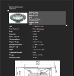
as for the tweeter probably gonna keep it on the same brand. just some mylar tweeter should be fine (don't worry that it can't reach 20khz its not intended for hifi, but I do wish it to be balanced enough) the tweeter no longer in the site specs but I still have the word document even tho its bare (screenshot attached)
question is what component should I need to cross it? & what order? also how is the schematic if I wanna combine it with the 220uf-330uf capacitor as well?
oh yeah also it got different impendance, (woofer 6 ohm, tweeter 8 ohm)
is 2 way vs 2 way with double woofer have different value for the capacitor & other stuffs? how to decide the value as well? how should I connect both woofer if I wanna go that route?
thanks in advance, best regards.
I planned to build a budget 5 inch bookshelf speaker (either classic 2 way, MTM or TMM) for learning purpose (I don't dare to start with expensive stuff because I don't have the equipment or the knowledge atm)
planned to use this local brand driver as the midwoofer which is dirt cheap (about 3-5 dollars each) :
https://acrspeaker.com/product/5-538-curve/
Based from the woofer parameter in the pdf, I should go with sealed enclosure (probably smallish one per speaker with qtc 1.1-1.2 & then add either 220-330uf capacitor, make it third order sealed)
as for the tweeter probably gonna keep it on the same brand. just some mylar tweeter should be fine (don't worry that it can't reach 20khz its not intended for hifi, but I do wish it to be balanced enough) the tweeter no longer in the site specs but I still have the word document even tho its bare (screenshot attached)
question is what component should I need to cross it? & what order? also how is the schematic if I wanna combine it with the 220uf-330uf capacitor as well?
oh yeah also it got different impendance, (woofer 6 ohm, tweeter 8 ohm)
is 2 way vs 2 way with double woofer have different value for the capacitor & other stuffs? how to decide the value as well? how should I connect both woofer if I wanna go that route?
thanks in advance, best regards.
Attachments
Last edited:
It's always easier if you can start with a pre-built kit. If you just want to learn the very basics please using XSim and try your hand with "ideal" speaker drivers. Virtuix is another very popular option but it may be too complicated. Simulate a 2-way in XSim and you'll have learned a lot.
Please remember that for a beginner like you, you are essentially asking others to design your entire speaker for you. Try to learn as much as you can, put together a design and then ask for help. There's a lot for you to learn. There's also a great thread pinned to the top about designing a crossover without measurements. That should be one of your first places to go.
Please remember that for a beginner like you, you are essentially asking others to design your entire speaker for you. Try to learn as much as you can, put together a design and then ask for help. There's a lot for you to learn. There's also a great thread pinned to the top about designing a crossover without measurements. That should be one of your first places to go.

thank you for the program u referring to. will definitely try that.
I can make something if its just a single full range speaker (basic, ported or sealed + a capacitor & then simulate it on WinISD + some plywood). but crossover for 2-3 ways is where I'm stuck because I can barely understand anything or how to connect them.
I always lurk in this site to learn as much as I can.
Almost forgot, Dayton has frequency and impedance plots for their drivers so it is a great resource to learn to make a crossover virtually and for free. 😀
lets say I wanna use these 2 as speaker.
https://sbacoustics.com/product/sb14st-c000-4/
https://sbacoustics.com/product/5-sb13pfcr25-4-paper/
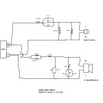
is this crossover close enough? (picture attached)
p.s. I tried the simulator but still can't get the hang of it, not using that for now (at least until I can learn on using it). plus I don't have any means to measure. so atm I'm just hoping from the online specs & do a bunch of calculation (head hurts)
result might be bad & gonna start all over again calculating stuff, but ah well gotta start somewhere for learn stuff
https://sbacoustics.com/product/sb14st-c000-4/
https://sbacoustics.com/product/5-sb13pfcr25-4-paper/
is this crossover close enough? (picture attached)
p.s. I tried the simulator but still can't get the hang of it, not using that for now (at least until I can learn on using it). plus I don't have any means to measure. so atm I'm just hoping from the online specs & do a bunch of calculation (head hurts)
result might be bad & gonna start all over again calculating stuff, but ah well gotta start somewhere for learn stuff
Attachments
Without modelling it you will not know approximately how well it works. The once built you will have to fine tune by ear, not easy.
Is it a local published circuit, some of the elements need their function explaining in more detail. I.e. why is there two inductors with one modified with a resistor and also in the bass leg, the impedance compensation of 35uF seems high.
In terms of achieving something that works correctly, doesn't the SB Acoustics Micro with downloadable drawings and crossover design already documented seem like a sensible choice for a first time build. Possibly the micro C if you have extra funds available.
See here https://sbacoustics.com/product/micro/
Your chosen drivers are fine, but they need correct cabinet and crossover to make them sing. Difficult to do this without good measurements in the first place.
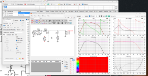
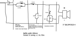
I had a quick look using the electro-mechanical properties of the 4 ohm 13cm PFC driver included in the VituixCad database. Approx 7 Litre cabinet. The impedance correction and inductors provide the indicated Xover slope.
This is not a full representation of what the frequency response will look like. It indicates Xover function based on the electro mechanical properties of the driver. It is useful to see Xover function, group delay, Phase and Impedance.
A powerful check of the basics in terms of the Low frequency leg of your Xover.
Attachments
thank you very much for the suggestion. I was looking at ur graph so that is what those zobel & baffle step correction circuit do. do note that the value of capacitor and inductor is basically what is available in my country (at least the film one for the caps, not electrolytic bp)
as for the sb acoustic micro. yes I'm also considering that (already read the manual back then). but not ready to buy the component atm. (don't have the time because of my work atm), in the mean time, as you said. I'll just try learn the basic first so at least I know what kind of stuff I'm dealing with
as for the sb acoustic micro. yes I'm also considering that (already read the manual back then). but not ready to buy the component atm. (don't have the time because of my work atm), in the mean time, as you said. I'll just try learn the basic first so at least I know what kind of stuff I'm dealing with
How i learned it was trough a kit, i build the kit and measured it (then still very primitive way) and tried to design many crossover for it, and failed many times. I even blew a tweeter. The kit had generic drivers and is not there anymore (it's 20 years ago) and the software was the excell sheet of Jeff Bagby. I measured it with a DPA mic and software from an acoustician i knew so i had the right data to start. And that is the most important, Measure your speaker in the cabinet on and off axis to start.
You could also find a cheap old second hand speaker, as long as it's a decent one it's perfect for this kind of exercises and cheaper/easier than building a kit in most cases. Get yourself REW (freeware), Xsim (Freeware) and Virtuixcad (freeware) and a measurement mic and audio interface (I use now a Dayton Umik-1 or a Behringer (don't remember the mode) that is calibrated right (don't trust factory calibration, they are not precise for the Behringer). and a Steinberg UM-22MKII interface (ad/da to the computer) and a mic stand. With those tools you can do the whole proces of measuring and simulating on data that is precise enough for this. It's a learning curve you need to go trough before you really know what to do, but once you know how this becomes less intimidating and difficult.
For learning what the parts do in a crossover, you can also use frd and zma files from the web, but those that are published are generalised and measured on a IEEE baffle, not your driver in your box. So don't rely on those to make your real crossover. But they are good excercise material (Dayton Publish them for all their drivers on their site). Start first with Xsim, as it works more flexible and intuitive than Virtuixcad. But Virtuixcad can do a lot more than Xsim. I use both, make the basic crossover in xsim and then finetune in Virtuixcad.
- Home
- Loudspeakers
- Multi-Way
- Need help on learning crossover