Modify Sony TA-5650 with half Vfet per channel as in 4650

Hi to all.
Having purchased a TA-5650 with half working Vfets, I wanted to ask the experts what modifications is necessary to make it work with only one pair of Vfets per channel, as in the 4650. The voltages for the power transistors are almost identical and it is probably only necessary to modify the values of some resistances. Thanks for the help

A Bookshelf Multi-Way Point-Source Horn

This originally started in this thread which asks the question "why aren't we building a bookshelf synergy monitor" and answers it with "we are" or at least "let's try and see what we get."

I got inspired back in the Trynergy thread to build a semi bookshelf point source horn

The results with the SB Acoustics SB65WBAC25-4 were very encouraging that Bushmeister went and ordered the drivers and some off the shelf waveguides to start experimenting.

So here is sort of my vision of the end goal. It's all very fluid and we try to make things smaller where possible. The reality is it might be closer to a small stand mount. Decisions of which WG to bass the system on sets overall size.

524229d1452489305-bookshelf-multi-way-point-source-horn-xbush-01-sb23nrxs45-8-design-sketch.png


Thanks to Bushmeister for the willing spirit to tackle this project. We are going to work together to come up with a new speaker with development and plans happening in real time ad hoc. It starts with Bushmeister picking the off the shelf 18 Sound waveguide.

Here is a summary of the completed speaker built by Bushmeister.

I guess we are calling the "XBush". Post 1248

Some highlights of the XBush:

Predicted sensitivity and response before EQ using a Harsch XO at 500Hz and SB23NRXS45-8 woofers:
536558d1457612468-bookshelf-multi-way-point-source-horn-xbush-01-sb23nrxs45-8-spl-sensitivity-2.83v-50mm-12mm-thick-65hz-hpf.png


The business side of the horn normally not visible when boxed up:
536573d1457612760-bookshelf-multi-way-point-source-horn-img_20160120_214528.jpg


Mounted inside cabinet:
536580d1457612930-bookshelf-multi-way-point-source-horn-img_20160203_072759.jpg


Finished speaker:
536582d1457612930-bookshelf-multi-way-point-source-horn-img_20160211_183015.jpg


Acoustic XO slopes for Harsch:
536584d1457613073-bookshelf-multi-way-point-source-horn-slopes.jpg


Harmonic distortion at 100dB and 1m (nice!). Note that this is just a 2-wa speaker with two sealed 8in drivers - that manage to produce nice deep bass extension with low distortion:
536585d1457613073-bookshelf-multi-way-point-source-horn-dist-2-.jpg


Measured acoustic phase:
536586d1457613073-bookshelf-multi-way-point-source-horn-phase-1-.jpg


Measured Horizontal Polar Directivity:
536587d1457613073-bookshelf-multi-way-point-source-horn-polar.jpg


Measured Vertical Polar Directivity:
536588d1457613073-bookshelf-multi-way-point-source-horn-vert-polar.jpg


Step Response:
536589d1457613073-bookshelf-multi-way-point-source-horn-step.jpg


Measured Group Delay:
536590d1457613073-bookshelf-multi-way-point-source-horn-gd.jpg


######### XRK971's XBUSH ############

Not fully up to snuff yet when compared to Bushmeister's amazing effort, but here is Xrk971's attempt which uses a Faital Pro LTH142 waveguide, dual Dayton RS180P-8 woofers, and same SB65WBAC25-4 mid/tweeter:

Internals with all 3d printed driver to horn adapters (here shown with early version using DC200-8 wofoer):
528945d1454484423-bookshelf-multi-way-point-source-horn-lth142-swcond-woofer-01.jpg


Later version with RS180P-8 woofers:
530860d1455371559-bookshelf-multi-way-point-source-horn-image.jpeg


Detail of SB65 throat adapter:
526756d1453501391-bookshelf-multi-way-point-source-horn-sb65-long-adapter-photo.png


CAD drawing of adapter:
526771d1453502400-bookshelf-multi-way-point-source-horn-xbush-throat-adapter-v3-wireframe.png


All 3D files (STL) for xrk971’s Xbush are here:
A Bookshelf Multi-Way Point-Source Horn

Fitting into box for first time:
529771d1454885057-bookshelf-multi-way-point-source-horn-baffle-black-1.png


Measured Polar directivity of SB65 in LTH142 waveguide:
526844d1453538138-bookshelf-multi-way-point-source-horn-sb65-lth142-eq-6th-fdw-polar.png


3d printed woofer to waveguide adapter:
527484d1453821187-bookshelf-multi-way-point-source-horn-horn-woofer-adapter-01.jpg


3d printed woofer chamber volume reducer plug:
527784d1453987194-bookshelf-multi-way-point-source-horn-woofer-mount-05-volume-filler1.png


Polar directivity with woofer holes:
528426d1454257077-bookshelf-multi-way-point-source-horn-sb65-lth142-eq-6thfdw-polar-vertical-big-holes-repaired-10db-scale.png


529809d1454908866-bookshelf-multi-way-point-source-horn-baffle-black-2s.png


Used in stereo with uTrynergy on left and Xrk's speaker on right:
531021d1455442962-bookshelf-multi-way-point-source-horn-utryn-xbush-stereo-setup.jpg


Acoustic XO slopes of Xrk's speaker:
534203d1456601648-bookshelf-multi-way-point-source-horn-xbush-harsch-xo.png


Phase of Xrk's speaker (still working on getting it flatter and proper 55deg phase bump for Harsch):
534204d1456601648-bookshelf-multi-way-point-source-horn-xbush-harsch-phase.png


Harmonic Distortion of Xrk's speaker (not very good - many leagues below what Bushmeister is able to do):
534206d1456601648-bookshelf-multi-way-point-source-horn-xbush-harsch-hd.png


I suspect the higher HD has to do with a number of things including: driver choice, cabinet volume and wall material, cabinet resonance damping methods, waveguide inertness via 4kg of epoxy Bondo, and larger holes (60mm vs equiv 29mm).
All pieces and adapters on Xrk's speaker were 3d printed PLA vs hand cut and epoxy for Bushmeister's excellent effort. Sometimes low tech gives better results.

So, my speaker is still a project waiting for more work to improve the phase, the step response, and improve the harmonic distortion.

JLE TPA3255 Build and Modifications

Hi all,
with JLE TPA3255 amp in the table, i am trying to shunt the input stage, which is unuseful because drived with a high level differential DAC (SMSL SU-9).
The JLE amp is design with PFFB topology.
Tried yesterday shunting input stages not working. Amp goes to FAULT.
What i had done :

  • Remove SE/BAL solder jumpers
  • Remove opamps from sockets
  • Connect J1-1 to socket A pin 1
  • Connect J1-3 to socket A pin 7
  • Connect J2-1 to socket B pin 1
  • Connect J2-3 to socket B pin 7

Something strange is near 2.9V DC mesured at the outputs AC blocking caps.


Another try is removing 100k input resistors to ground (RA1, RA2, RB1, RB2). Same results.

PLL not working on Kenwood KD-770D - Suggestions Appreciated

I have a recently acquired Kenwood KD-770D with a speed problem. It appears that the PLL is not working because the table runs about 54 RPM at both 33 and 45 settings. PLL lock LED doesn't engage. I'd appreciate any suggestions on troubleshooting this table, thanks.

EDIT: I'm just looking for suggestions based on prior experience with this table (or similar, e.g. KD-990). Just trying to shortcut the solution with information from someone who's already been there. Cheers.

For Sale Gaincore a single ended Sit amplifier and A2Cmx-V pcbs or finished modules

Hello,

I have for sale a few pcbs or finished modules for this amplifier.
IMG_9070.jpeg


More info about the Gaincore can be found here.
This amp is capable of giving 25wrms/8r with very low thd using a single 29.5vdc power supply.
It accepts sits and mosfets(to247 and sot227(pucks)).

The A2Cmx-V hosts an A2Cmx filter like this one and a negative rail converter this way you need a single rail power supply.

As a minimum requirement for the choke you will need 60-70mh and 2a.

2x Gaincore pcb + 2x A2Cmx-V pcb - 40€
2x Gaincore module(without Sit) - 140€
2x A2Cmx-V module - 120€
  • Like
Reactions: mordikai

Williamson first stage question

Hello. Working into a Williamson project, kind of. I can get 100 Vdc above onto the first plate supplying the first stage with the same 400Vdc as cathodyne did with 100k plate / 1k cathode resistors. I know the original scheme used 47k/ 470 ohm suplied at 250v above to get the same current. But the swing is minimal, I drived the amp with 200mVpk without nfb applied. Does it make a dramatic difference in respect with original circuit please ? Thanks.

This is my actual circuit.

Attachments

  • 20240325_102911.jpg
    20240325_102911.jpg
    164.9 KB · Views: 414

Valve base extenders

Hello!
I just wanted to share something I found on eBay UK. Sold as base extenders, seems pretty useful to test tubes that are not pin-compatible with an existing amp or a tube tester.
Search for "McMurdo B9A Vintage Valve Base Extenders - Set of 6"

Attachments

  • PXL_20241110_125231732~2.jpg
    PXL_20241110_125231732~2.jpg
    299.8 KB · Views: 71
  • PXL_20241110_125313208~2.jpg
    PXL_20241110_125313208~2.jpg
    223.3 KB · Views: 63
  • PXL_20241110_125329741~2.jpg
    PXL_20241110_125329741~2.jpg
    191.2 KB · Views: 67

Dynaco FM-3

I just scored a Dynaco FM-3 for $60 to complete my Dynaco system. I’m going to clean and refurbish it. Are there any common things I should look for? I’m debating on changing out all the carbon comp resistors with new metal film ones. I’m going to replace the multi cap with individual caps under the deck. I’ll also do electrolytic to form on any signal path caps. What else should I look at?
  • Like
Reactions: Capt Grogg

Edge Trigger Circuit

I'm building an old school distributor machine for testing vintage motorcycle ignition systems. I want to flash LEDs to indicate when the ignition pulse is happening and would like to use 12V to trigger them to avoid needing the high voltage coil and spark plug. One hurdle I'm running into is the dwell time of the ignition pulse is far too long. The LEDs stay on too long to see any timing marks.

I've been searching for edge trigger circuit designs that will work for me but every one I've in come across the minimum on time is at least as long as the trigger pulse. I can make a microcontroller see a rising or falling edge and flash the LEDs for a few microseconds but it seems to go erratic at the upper end of the RPM range.

Does anyone know of an edge trigger circuit that can have an output that's shorter than the input pulse?

What NOT to do with L15D board!

This: (one of the L15D boards in my 7-channel amplifier):

Top (Medium).jpg Bottom (Medium).jpg

Not actually sure what caused it as all I did was change an opamp in the phase inverter buffer. :sad: But it was quite exciting, with :flame::flame:flames:flame::flame:, noise, and magic smoke everywhere! And it even blew the VCC leg off the opamp "Is something burning?" asked my wife, "Nothing to see here, move on", I replied sheepishly 😱. Lucky I have a spare board and inverting buffer.

But I have a question. Should I have fuses between the +/-55V 500W SMPS and the L15 boards, and if so, what value fuses should I use? And should I put one fuse in the +55V rail and another in the -55V rail?

TIA, Jon.

Phase question about piezo tweeter

Hello all. I'm hoping someone more knowledgeable can help me out with the electronics on my filter. I'm using a piezo tweeter in a two-way with the following filter on the piezo: a capacitor in series and a parallel (shunt) resistor across the piezo element. I'd like to know how phase is affected (if at all) by this type of arrangement. As far as I know, piezo elements also behave like capacitors in circuit.

Thanks for any help. Let me know if I should post this in a different section.

Rackmount guitar rig using a mini-PC + DAW with custom built speakers

(reposted to the correct thread bc im stupid) Howdy guys. Sorta new here. I'm really just posting this to show off what I've been working on for the past few weeks, but all tips and suggestions will be much appreciated:

IMG_8457.jpg
IMG_8463.jpg


The idea was to make something akin to a traditional guitar amplifier, but with a little more versatility. I had a few parts laying around: an old mini-pc, amplifier, and a Focusrite USB interface. To make use of them, I settled on using the standard 19" rackmount system to mount whatever I needed. Funny enough, there is not a single consumer-grade piece of rackmount audio equipment in there (dedicated EQ, compression, etc.) This was mostly by design. The mini-pc allows for fully digital effects (basically anything you can imagine), so there's little point in buying even a simple 1U signal processor. Moreover, more metal in the case = more weight. Portability of this system is very important. If I were to add something like that, it'd probably be an EQ, but I am full up on rack space in the front.

Anyways, I settled on a 6U rackmount flight case. 17" deep, 19" wide. It has a cover for front/back which is quite nice for portability. The covers themselves have zippers and can hold things - very nice.

From top to bottom, here are the components on the front of the rack:
1st U: Sliding tray with portable 15.something" monitor. Hold a bluetooth keyboard+touchpad combo.
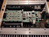
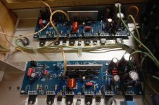
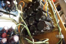
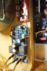
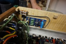
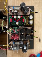
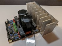
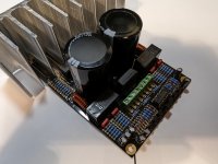
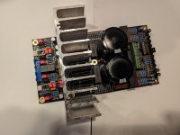
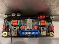
2nd U: Fixed tray with Beelink s12 mini-pc, Focusrite interface (2nd gen), and a fosi audio 2.1 amplifier
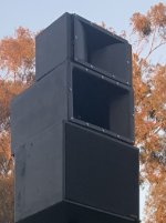
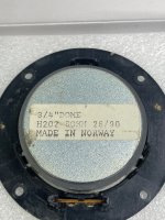
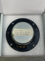
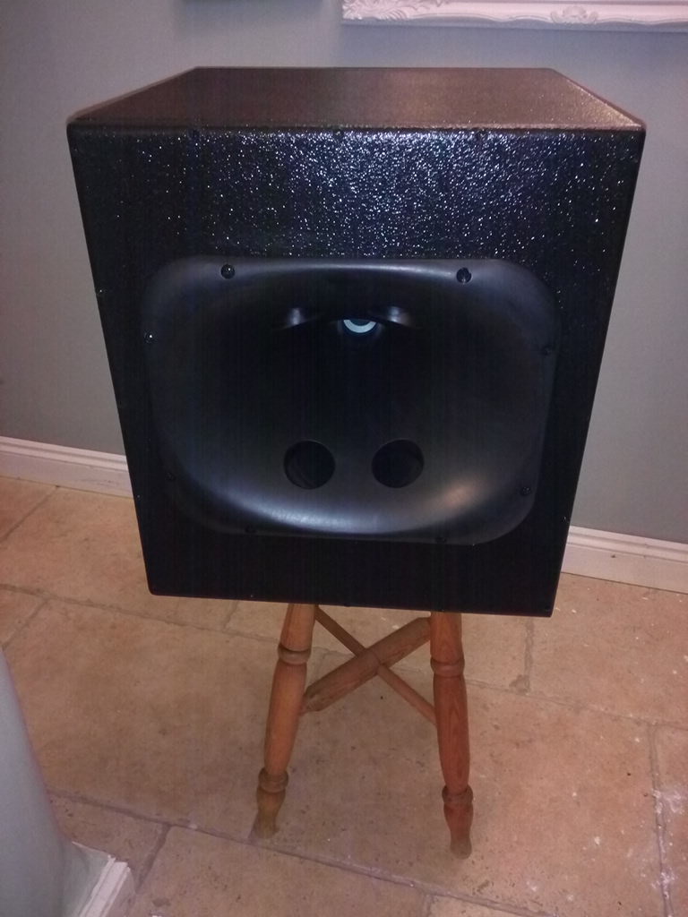
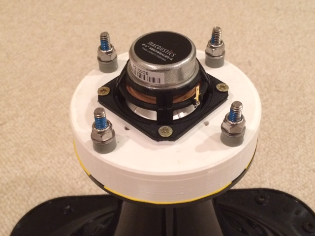
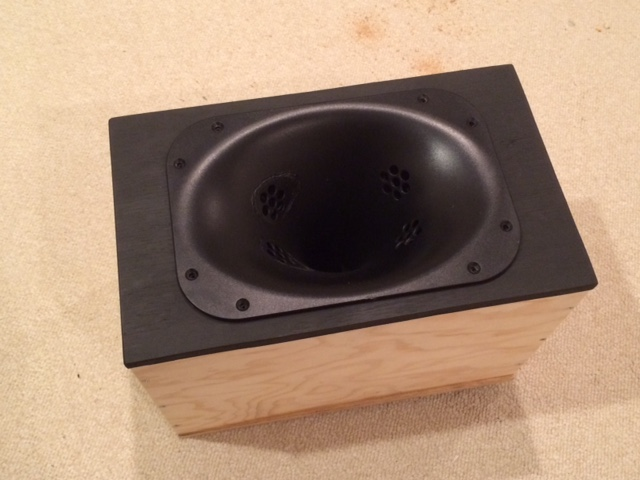
3-6th U: Speaker solution. Material is either MDF or 3D-Printed (PLA). Many different speakers have been used: Marcaudio fullrangers, Fountek fullrangers, SKAR audio coaxials, woofers stolen from various studio monitors, and a Dayton audio 7" woofer (newest addition).

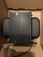
The back of the rack holds only the PDU. Just don't look at my solution for mounting the sliding tray. I'll probably be filling the rest of the back with a blank panel covered in acoustic foam. What do you guys think about that? Because I've just been running these speakers with the back of the rack OFF, creating a pseudo open-baffle speaker. Still sounds alright.

IMG_8453.jpg
IMG_8454.JPG

IMG_8456.jpg
IMG_8462.jpg

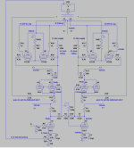
Signal chain: Signal sent to the interface is sent to the mini-pc which is then processed by FL Studio, and then sent back out the interface into the amplifier via RCA. Speakers are passive.

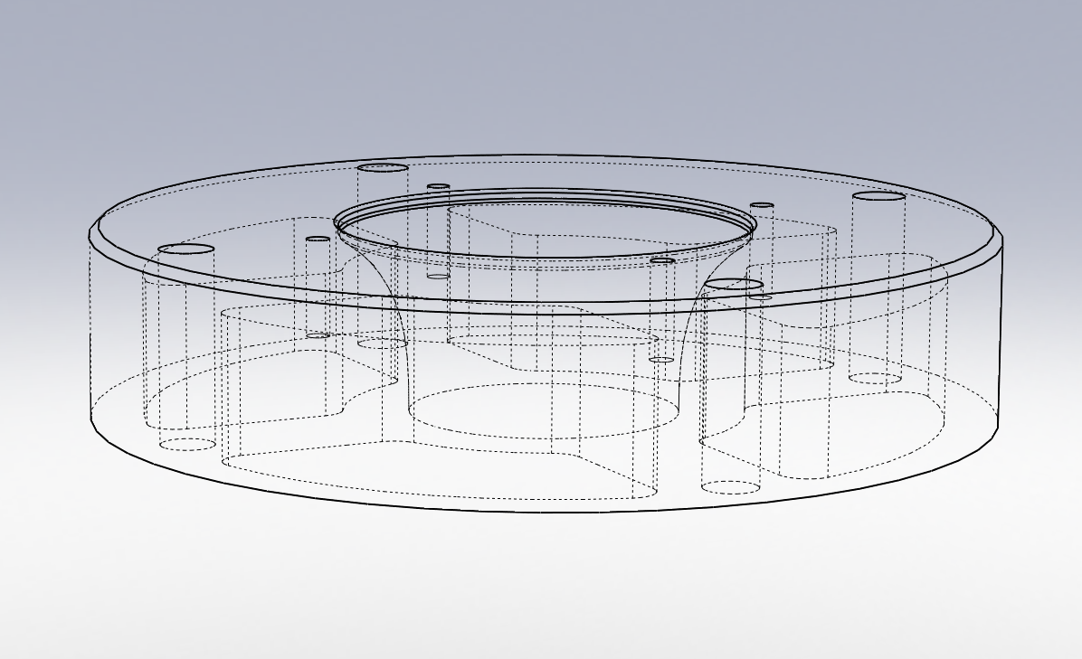
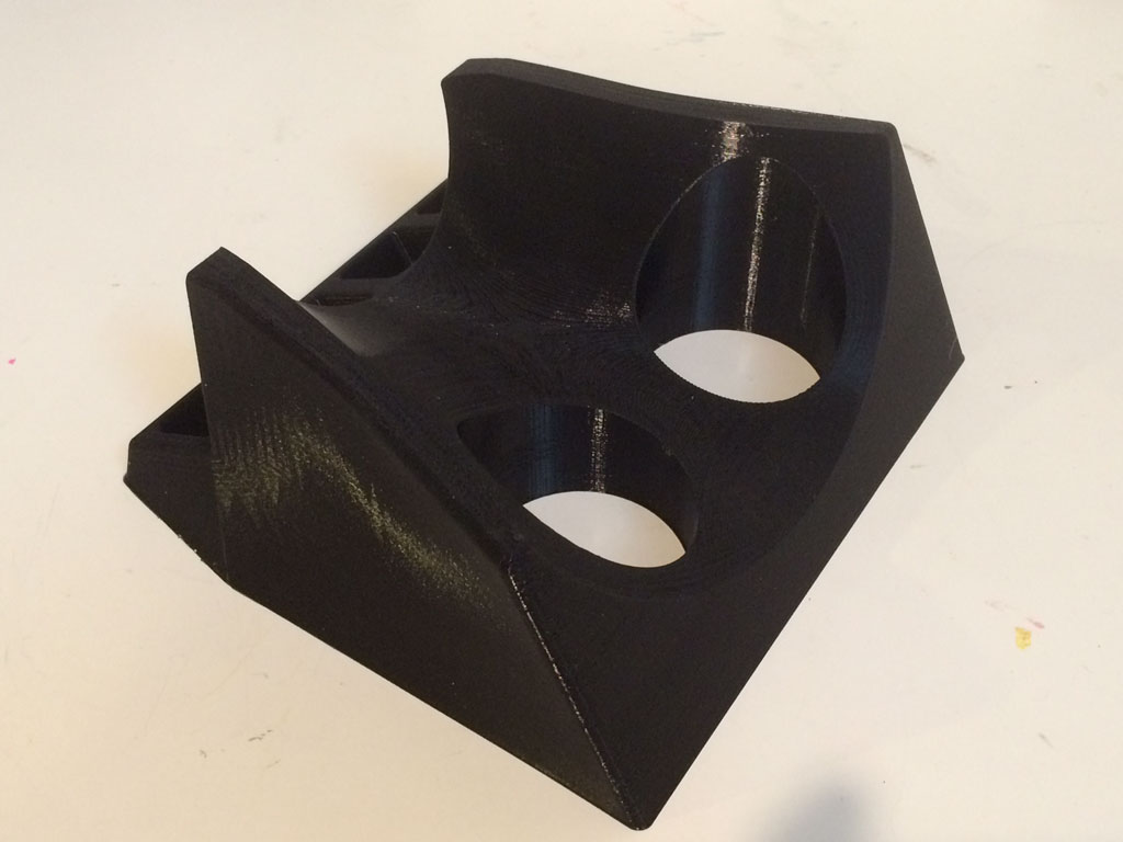
Speaker solution: The most challenging part of this was designing a "baffle" that would house speakers and sit within a standard rack. If you look up "rackmount speakers" you really don't get anything useful for this application. Why? Because this is an insane niche that never needed to be filled. What you find on google are these weird audio monitoring speakers that are very nearfield. So, I had to make my own thing. At first, I was able to get away with it by sticking a Kenwood CRS-158 on a shelf inside the rack. That worked good enough as the center speaker was exactly 17" wide, but it took up about 3.5U of rackspace, leaving lots of dead space. I started making designs on TinkerCAD and sent them to a guy who routes MDF and a co-worker that does 3D printing. So far, the only difference I've noticed between MDF and PLA is WEIGHT. My god, even with more/heavier drivers in a 3D-printed baffle, it's lighter than any MDF baffle. I'm sure there are drawbacks to PLA acoustically (not totally infilled, resonant maybe?) but my ear really hasn't heard a difference.

IMG_8458.jpg


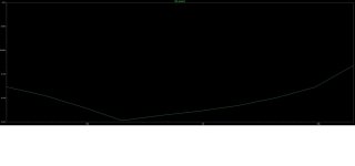
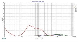
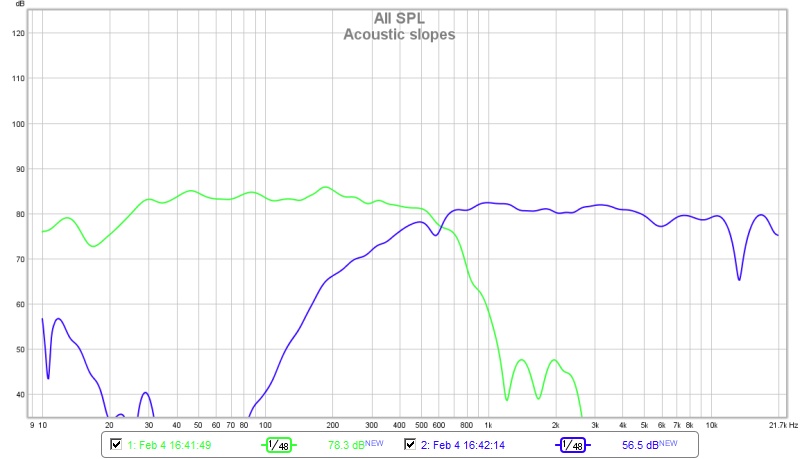
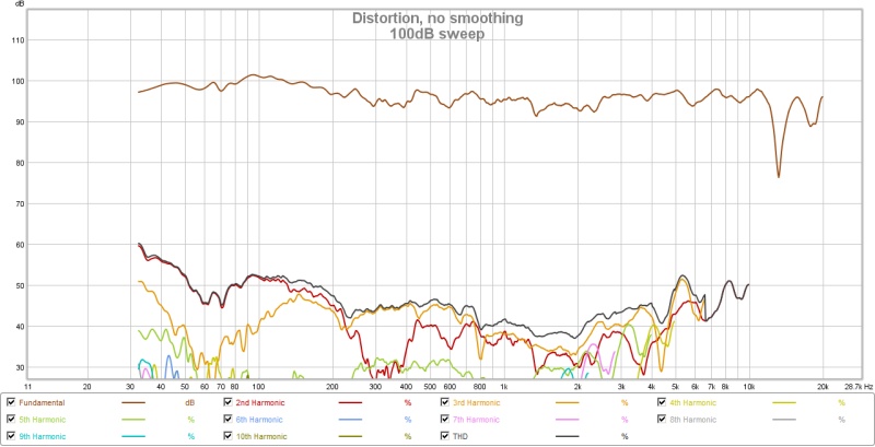
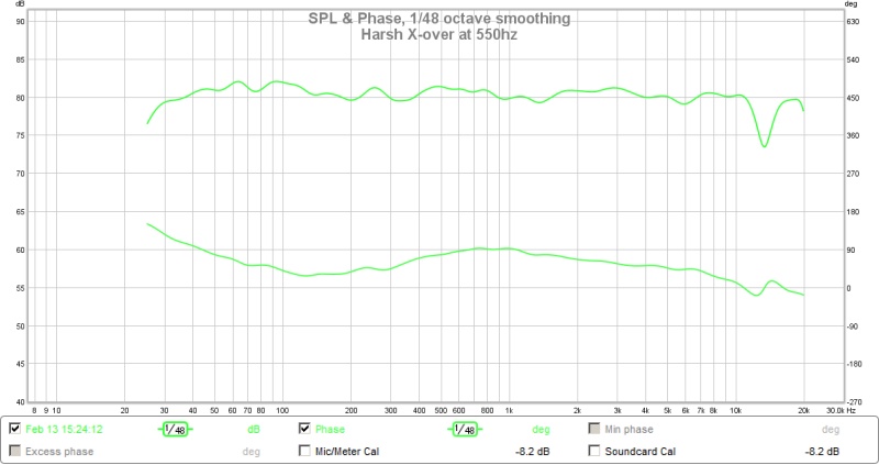
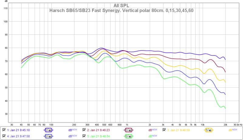
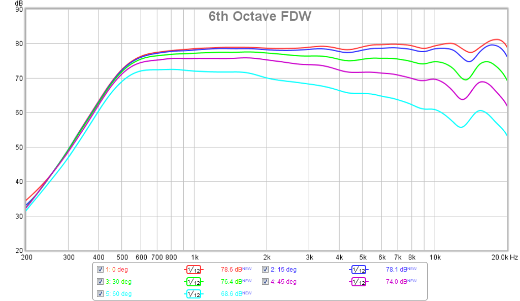
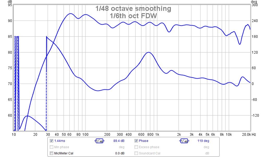
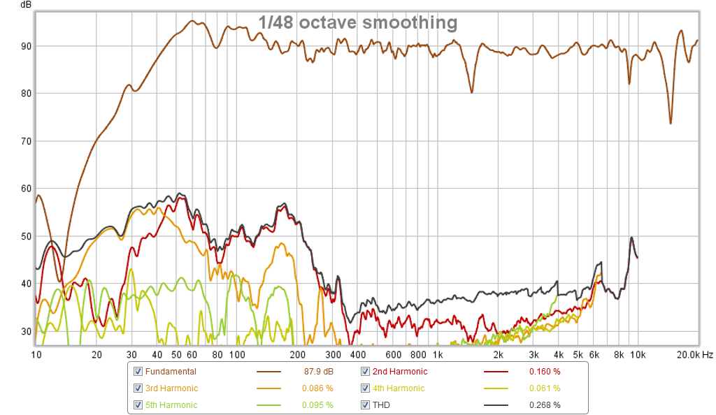
Drivers, how it sounds: I got a combination of full-range drivers and woofers and just started trying them out. It sounded pretty damn good in the beginning, despite the cheap/small speakers and shoddy measurements. But I quickly realized that I needed to optimize for speaker size, as a 4" speaker is NOT going to reproduce 60-70hz (I downtune my guitar), especially in this enclosure. Enthused, I went ahead and got some nicer speakers with a good cone area. These were the CHP-90s from Marcaudio and a 7" woofer from dayton audio, paired with some smaller fountek full-rangers(I also got some 4" marc audio drivers, the CHP-70s, those didn't work out very well in terms of response). Now it's sounding really nice to me. It fills to room, produces bass, and just lets me vibe out. I have yet to measure the frequency response, but I'm sure it's ****** in some way.

I settled on a 2.1 amp so that I could use a dedicated woofer if needed, reducing stress on the full-rangers. Uniquely, this allows me to run the speakers in stereo, which is actually quite noticeable, especially on my "2-way" baffle. The focusrite interface allows the system to receive two signals at a time. Some fiddling around with my DAW (fl studio) allows me to assign different inputs to different speakers, if I really wanted to. I'm also exploring ways to angle the smaller full-range drivers outwards to get a better stereo image. Basically a toe-out.

It really is more than just a guitar amplifier. As I play my guitar, you can send MIDI signals to FL Studio via USB and at the same time be using an XLR input from a vocalist for example, all while drums are looping on the playlist. And you can record it all. That is really ******* cool.
Some problems I battle:

VIBRATION:
oh my god, does this thing like to vibrate. At med-low volumes, there is no issue. The moment you go past any reasonable listening level for a small room, the entire case and the contents within begin to resonate at particular frequencies. To account for this, I need to remove anything that is sitting on top of the case. Make sure that all screws are tight and even. Use many rubber washers. I've also stuck a few vibration-absorbing gels around the inside (you know, the ones drummers use on their snare), who knows if that's done anything. I guess I'm sort of asking for it, sticking speakers in a plastic enclosure which houses several different components fixed in weird ways.

COOLING: After I added the 2.1 amplifier, thing get kinda toasty in there. I mean the pc, interface, and amplifier sit right next to each other. It hasn't necessarily become a problem yet, but I'm exploring lightweight, quiet, and unobstructive cooling solutions. I'm thinking of a 1-2U panel lined with noctua fans.

PORTABILITY: This really just means weight. This thing gets heavy quick, as rackmount equipment is almost always full metal. Any addition must pass weight consideration. Also, I definitely don't need 17" deep in my rack. I could probably get away with 12" deep, just to reduce bulk.


Let me tell you, I ******* love this thing. It gets loud, shakes my room, and is just overall so much fun to play with. I've spent so many hours modelling cabinets and playing with effects. I just got so tired of playing guitar on my "main" computer, and said screw it, I'll build something legit. And lord knows I'm not dropping $500-1000 on a decent guitar amplifier when I can drop the same amount of money to build something truly unique and more versatile. Don't get me wrong, guitar amps are cool, but this is RAD.

QWAY.PNG
2WAY.PNG
Capture.PNG
  • Like
Reactions: RRPD4130

simple amplifier for turntable synchronous motor drive

This is a companion amplifier to the synthesised sinewave generator, for driving low-voltage 2-phase motors.

There are many amplifier modules available, but due to the output voltage swing required, these will typically have quite a high power rating as they are intended to drive low-impedance loads, which is not needed for this application.

An Analog Devices application note shows a high-voltage amplifier which seemed promising for this application, using an op-amp with supply current sensing and a potential divider on the op-amp output to provide both a current boost and allow the high voltage rails:

AN106_excerpt.png


A 2-channel amplifier suitable for a low-power synchronous motor based on this concept has been produced (non-inverting, zener references), using mostly non-critical parts. The TL071 op-amp proved suitable, with the only critical component being C1 for the stability of the current feedback loop:

Schematic_spinamp.png


With C1 of 1nF, step responses at 70Hz (left) and 5kHz (right) are good:

ref5b.png
ref5c.png


A PCB is available, Gerbers and build guide are attached to this post.

20210317_210756.png


Full details also on my GitHub

Attachments

intro

Dear All,

Greetings from Poland. It has been a while since I started the journey with electronics. Started from scratch 2 years ago, learning from yt, books and forums I have had a good time with building up some diy kits.
I would like to get to know with you, sometimes to ask for a support. BUT first and foremost - to have a good time with audio I create by myself 🙂
Building some simple DAC, headphone amp and dual mono amplifier have given me a real lesson, and still does.
Currently I am working on preamp kit of Bryston clone bp26, which will be my 5th project 🙂
BEst regards to everybody!
Umetek

Krell F.B.I integrated amp shuts down

Have a integrated Krell F.B.I sins it was new ca 2008.( but dident use it before 2011-2012 due to various reasons and health)

https://www.stereophile.com/content/krell-fbi-integrated-amplifier-specifications

And last 12 years it have been driven first my 1998 Von Schweikert VR-4 SR, and last 3 years my diy speakers 6 X Peerlees XXLS 12 inch modelnr:830847 ( 2 x 8 ohm coils, 3 per side tuned to 23 hz, in 100 liter reflex netto) each connected 16 ohm at the driver, and parallell to 5,66 ohm outside.

Active filter before amp, so Krell amp and XXLS 12 do the jobb up to 340 hz left and right ( Unother amp take midrange and top from 340 hz an upp left and right, passive xover in MTM)

Im a real high listener, mostly over 100 dB + the 15 dB peaks, so Krell amp have to work ”hard” and always get very hot on my 3-4 hours of playing now and then.

Suddenly when im listening the amp shutts down itself. (protection mode ?)

Started it up again after a few minuts, and all seems fine. Dident play as loud the rest of the listening, but it newer happend agian that night.
2 weeks after when i played as laud as i use to do it happend again, the amp” shutts down itself ( and now i begain to be worried)

Let it be for a few month ( dident have health to deal with it), and when deside to listening again i shifted the speakerconnetion so the Krell only do the mid¨s and top MTM ( for a more easy load)

It played my MTM for 2-3 secunds and then amp shutts down itself again…Grrrrr

Hade A friend brought the 55 kilo amp up from the basement & put it on my kitchen table for me, and i connected it only to 240 volt power and power it up ( no speakers or soundsourses connected) and everything seems normal (it has a 10 second start-up sequence before it goes to ready-mode)

Let it stand in ”power on mode” for an hour and them measure DC offset at the speaker terminals. The meter setting was 200 m, and both left and right speakeroutputs shows value from 010 minus to max 035 plus ( was ofted at 003)

My question is where do a go from here?

Connecting a soundsourse? Speaker ? and measure again?


Best regards John

Attachments

  • IMG_20241031_150645.jpg
    IMG_20241031_150645.jpg
    526 KB · Views: 148

Designing/ Making a Linear Tracking Tonearm From Scratch

Hey everyone! I'm a senior in college and I'm designing a turntable for my senior project. I'm interested in designing and building my own linear tracking tonearm, but I'm a beginner in audio electronics and could use some help figuring out what parts I need and how they generally work. If anyone could provide some guidance on where to begin it would be much appreciated!

Small bookshelf sanity check

Good morning from beautiful Worcester, MA!

I'm designing small bookshelves for a little media room (TV, computer, games) and my wife wants them as small as possible of course 🙄 The room is about 3 x 4 meters and I will make a subwoofer for <80 Hz later on.

I want to do a narrow baffle using the Peerless SLS-P830945 5-1/4 inch woofer with solid wood on both side aligned right to flat faces of the Peerless. So it'll be easy to make a ported 3.5 liter box with a 5 inch baffle.

For the full range, I was considering a MarkAudio driver crossed around 500 hz, first order if possible. I was considering using the Alpair 5.3, but the CHN-50 is less than half the price and seems to be very similar? Does anyone have experience with both and can clue me in to what I should be looking at to make a decision?

Obviously I haven't taken measurements yet, but playing with curves in WinPCD it seem a 1st order with the Alpair (80 uF) and a 1st order + Zobel on the Peerless (1.3 mH / 17 uF - 3 Ohm) behaves rather well. That said, I'd love your suggestions or criticisms.

Thanks
  • Like
Reactions: jaakkopetteri

Star Earthing - At control unit? At power amp ? At commoned speakers' grounds?

I have an earth loop which I'd prefer to leave in place and hoped wouldn't matter. Yes this problem is as old as the hills but not quite like mine. This is a long one. Perhaps you should visit the small room before proceding, and then only if you'd otherwise be bored.

No problem with line level signals but when the gain is very great - amplifying 5mV phono up to 20 Volts into speaker loads - I get low a frequency feedback howl which is so low as to be almost subsonic when the gain is turned up. This because RIAA gain is highest at low frequencies.

The situation is:
Two sets of speakers (electrostatic and dynamic) crossed switched from two amplifiers (valve and transistor). One amplifier is a stereo integrated amp and the other (valve) is a stereo power amp. Nice set-up.

Unfortunately I have to use the integrated amp's phono stage via its tape record outlets to drive the valve power amp. All signals except phono are attenuated and switched to either amp outside of both amps. Both amps are earthed to the house mains.

Here we go.... Both amplifiers' speaker minus outputs are connected to their respective mains earths - neither amp works in bridge-mode. I've commoned all speaker minus inputs and all amplifier minus outputs. That's 8 wires connected together. All live lines are switched with two DPDT switches.

[ Imagine two simple stereo two way speaker select switches mounted back to back with their commons connected together. One box switches the speakers conventionally, the other selects the amplifiers working backwards. They wouldn't need to be four pole switches because it wouldn't matter if both pairs of speakers got one of the phases provided the other phase is switched to either one of them. Maybe some good switcher boxes do it properly with a four pole double throw. Thinking abt it I reckon that would solve my problem just wouldn't be as neat as my purpose-built switch box]

Needless to say if one amp (the valve one) is simply unplugged from the mains the problem goes away.

Aside from the safety aspects, mitigated by bloody great labels saying "This device's earth is disconnected at the plug", Where do I put a (very high current) mains-earth path for star-earthing?

My guess, in my situation, would be to the 8 commoned heavy-wired speaker ground-lines, with a ninth connection to a dedicated mains plug with a single green and yellow conductor from its mains earth.

But OK, back to the real world, would it correctly go? To the deck/tuner, the control unit or the power amp? My guess would be to the power amp. But in any such case, you'd have signal lines carrying massive fault currents from the other components' failures.

Got it! Run everything from individual isolation transformers! Hang on, then how'd you know there was a fault......?

Trying to repair my failed Sumiko S.10 subwoofer. There is a burn mark on the board.

This is my first real post on this forum, so hopefully I'm following protocol and etiquite.
I few years ago I bought a Sumiko S.10 subwoofer. I really enjoyed it, but eventually it just stopped working. I'm far from a DIY audio guy, but was brave enough to remove the board from the back of the sub and look it over. I don't know anything about electronics, but found something that didn't look right. There is a burn mark on the board. Check it out on the bottom right of the image:

PXL_20240121_173540186.jpg


Here's a closeup of it:

PXL_20240121_174200561.jpg


I spoke with the US distributor of Sumiko. They told me they could sell me a new board, but it came with no warranty whatsoever. Given the reputation of these boards failing, that didn't sound appealing to me. I'm told I can salvage the sub just buy installing a different plate amp from Dayton or Parts Express. I don't really know what to buy, though. Also, I was under the impression there should be just a couple wires to hook up, but it appears the Sumiko has more than that. I think if I can figure out how to wire the correct aftermarket amplifier to this thing I can get it working again. A friend of mine has offered to mount it properly to the back of the sub. He works in a fabrication shop and has some experience with that sort of thing.
So here are my questions:
1. Should I buy an aftermarket amp for it?
2. If so, which one?
3. What do I need to do to wire it up properly?
I'm not afraid to spend a few extra bucks to make the amp sound at least as good as it did originally, if not even better.
Here are more pictures of the subwoofer internals that will hopefully help:

PXL_20240202_175424697.jpg
PXL_20240202_175815641.jpg
PXL_20240202_175819240.jpg

PXL_20240202_175833122.jpg
PXL_20240202_175853247.jpg
PXL_20240202_175957598.jpg
PXL_20240202_180041608.jpg


If anyone has guidance for me I would really appreciate it.

Testing protocols for ideal volume of sealed space behind horn loaded cone

I built a modular three-way PA cabinet for Small concerts, it uses a 3 inch compression driver, a 10 inch cone, both horn loaded, and a 15 inch in a ported box.

It's working great, but it needs refining.

My main concern is about the 10 inch driver. It (and the compression driver) are out of EAW KF 650's, but new horns.

I attached a PDF of a driver which I have heard from multiple sources is virtually exactly the same as what they put in the EAW.

The difference in efficiency between the 10" and the 3" is larger than when these were in KF650's. Believe it or not, the sensitivity spec for them were the same in a kf650, and in practice I even backed off the 10" sometimes.

I'm not sure if it's due to the airtight enclosure I made behind the 10" being the wrong size, or the horn change, or something else.

Based on what I learned from helpful people on this site and reading articles, I created an airtight enclosure for the back of the 10 inch driver.

But the volume of my cavity (term?) is larger than the manufacturer specification, and I'm getting ready to address that.

Is that specification a starting point, or something to strive to match precisely? Does what kind of horn the driver is connected to influence how much volume should be behind it? Should I experiment with different volumes, and if so, what protocols/criteria should I use to assess which volume of cavity is best?

Attachments

  • l10-750yk.pdf
    l10-750yk.pdf
    544.6 KB · Views: 56
  • IMG_8196.jpeg
    IMG_8196.jpeg
    169.7 KB · Views: 57

ACA Mini Listening Impressions

Third post from a novice builder of the Nelson Pass designed ACA Mini amplifier. My amp is built and biased, and I've spent some hours listening to it. My impressions follow the photo of my completed amp.

IMG_20230804_141526156.jpg


I have listened to the ACA Mini, well warmed up, in two systems, and now I venture to offer some impressions.

System 1 (cobbled together): WiiM Mini streamer, Schiit Modi 3 DAC, Schiit SYS (volume control), ACA Mini, PSB Alpha T20 speakers (small floorstanders, about 87 db sensitivity).

System 2 (main living room system): WiiM Pro streamer, Denafrips Ares II DAC, Schiit Saga+ hybrid preamp with a 1946 RCA gray glass 6SN7GT tube, ACA Mini (in place of Schiit Aegir), JBL Arena 170 speakers (somewhat larger floorstanders, stated sensitivity of 86 db [I think], but really more efficient than the PSBs).

Impressions: The ACA Mini has incredible clarity in the treble and high mids, with a fantastic soundstage. This is where it really stands out. What it lacks is heft in the lower midrange and bass. My thought is that it has a good skeleton but could use more muscle.

The tilt toward the treble at the expense of lower mids is particularly noticeable with vocals and instruments like acoustic guitars, where the fundamentals are in the lower midrange.

Also lacking at the low end is a degree of impact necessary for a realistic piano left hand, not to mention drums.

By contrast, the Aegir excels with lower mids and bass. It has very detailed treble, but here I could give the nod to the ACA Mini.

If my Aegir was out for service, I could easily enjoy music with the ACA Mini in its place. Not bad!

Thanks to Nelson Pass for offering this kit to us. I had a ball building it. Honestly, I felt like a teenager, learning, doing, and having fun.

For Sale M2x Amplifier and Academy Audio Muses Preamp in Black (all Daughter boards included)

I recently switched to Magnepan LRS+ with balanced F4s and this M2x I just built I won’t need. The chassis, PSU, and transformer are brand new but the boards were previously used by a friend but he needed more power so I traded for the amp back and repurposed parts. The daughter boards are all stuffed and work. 60,000uf in filtering, Vishay resistors, Nichicon caps, and covers for the Edcor transformers. Transformer is an Antek AS-4218. With near 100 db efficient Klipsch speakers the amp only has a tiny hum with my ear 1 inch from the speaker. I’m sure I could have gotten it quieter using shielded RCAs. Dissipante chassis from Modushop and Norwood boards are currently installed.

The preamp I used all parts from Academy Audio. It has the LPS9 PSU, VCX volume control, and BIB balanced input board. It has 3 balanced inputs and 2 RCA single ended outputs. The PSU is a Meanwell 5V that allows you to use your favorite power cable. I also included the standby switch that allows you to easily flip the unit to mute and you can program the VCX for another type of remote. Galaxy chassis from Modushop and remote is included. If you plan to use single ended sources, I can offer some cables for cheap that are single ended to XLR.

I’m asking $1200 for everything and I’ll ship it for free. I would love to sell these two pieces together.

Texas Instruments Low Distortion Oscillator Diode Question

Hello there.
In the Texas Instruments application note AN-263, it describes a Wein Bridge oscillator that is enhanced by the addition of a FET. The diagram shows a 7.5V Zener diode in the circuit. Now, typical op-amp circuits presume a +/- 15 volt power supply, but I might have to use a +/- 12V Supply. It seems not unreasonable that this might affect the voltage that one would use for the zener. The scope traces on the page show the circuit using much of the 15V rails. Is there some reason that I might want to change the Zener diode voltage from what is shown?

Oscillator 11 10.jpg

SEAS H202 8 ohm, 3/4" dome tweeter, NOS, Rogers, Mission, Kef and other vintage speakers

SEAS 3/4" dome tweeter
H202 8 Ohm
NOS...new condition
Asking $45 or best offer.

Rogers, Mission, Kef and many other vintage speakers.

Attachments

  • IMG_9631.jpg
    IMG_9631.jpg
    539.8 KB · Views: 72
  • IMG_9633.jpg
    IMG_9633.jpg
    465.2 KB · Views: 57
  • IMG_9634.jpg
    IMG_9634.jpg
    633.3 KB · Views: 58
  • IMG_9635.jpg
    IMG_9635.jpg
    589.8 KB · Views: 56
  • IMG_9636.jpg
    IMG_9636.jpg
    620.1 KB · Views: 52

Active crossover with dipole compensation?

I'm currently using a Behringer DCX2496 to handle the low end of my dipole speakers.
I used to have an analog active crossover, and I think it had better sound quality. Unfortunately it got lost during a move.
This was years ago and I can't even remember who designed it for me.

Long story short(er), I am asking if there are any schematics around for a two way active crossover with dipole compensation and volume control(to match volume with my passively crossover mids and highs).

So, what I am looking for is a circuit where I can set crossover point, adjust dipole compensation and a volume control for the board.
TIA

For Sale Dynaudio 21W54 8ohm (pr)

Removed from a 30 year home build that never performed to expectation. Mostly in storage but it is time to go. The surrounds were replaced at some point and are still serviceable. There is weather strip tape on the rear flange that I didn't try to remove. Not going to try and price . If you have a use make an offer. Please include enough to cover shipping from WI. I also have D260 SQ tweeters that still look like new. I will post them if any interest. Also have published spec sheets from Madisound.
PXL_20241110_141421178.jpg
PXL_20241110_141436137.jpg
PXL_20241110_141505279.jpg

>100W opamp based amp

Welcome to my fist thread.

during the last few weeks i've been reading about discrete amplifier designs, for example Blameless and wolverine, and was looking for a challenge to design my own high end amplifier. but with a twist to make it challenging and unique. that's when i came to the following thread: https://www.diyaudio.com/community/threads/mosfet-audiophile-amplifier-with-opa-driver.341751/
I decided to take on the challenge to design an amplifier with an op amp input and gain stage while being high end.

the following limitations are put in to place to make the challenge of design more difficult:
  1. the input and voltage gain has to be done by op amps
  2. a minimum avg. power of 100W with an 8 ohm load.
  3. minimum gain of 20.
  4. "wolverine" like performance regarding THD.
  5. minimum of 2 mV ripple on PS rails.
  6. maximum of two output devices to keep the design tiny (optional if large improvements can be made).
i know discrete would be cheaper and no more or less total parts but that's not what DIY is about, aint it?
so you can find my concept in the attachments. you also can find the analyzer settings there.


i hope you all have some input to improve it even further or learn something from my concept.

thanks to these members for their contributions to this project:
Mark Tillotson
steveu
xrk971

Best regards,

ImpatientIcecream

Attachments

Honey Badger w/soft start populated boards

I have a set of Honey Badger boards that I put together. I used it for a few weeks before eventually having a thermal runaway problem. I'm not able to troubleshoot it myself.

Nothing smoked but it got quite hot. I don't know if any parts got damaged.

Whoever buys it needs to be able to troubleshoot. I haven't tried to use it since having this problem. I am also including 12 Panasonic 8200uF caps, and a DIY Audio soft start and DC protection circuit. This was all bought new in 2014. Everything is sold as-is.

$130 US FIRM shipping included to anywhere in North America.

Attachments

  • DSC07571.JPG
    DSC07571.JPG
    280.4 KB · Views: 257
  • DSC07572.JPG
    DSC07572.JPG
    285.3 KB · Views: 255
  • DSC07573.JPG
    DSC07573.JPG
    345.8 KB · Views: 226
  • DSC07577.JPG
    DSC07577.JPG
    225.5 KB · Views: 269

  • Locked
ChatGPT on J2 or F5 for Klipsch Heresy

It is not often that we talk about which loudspeakers are best suited to various First Watt amplifiers. Have built 2 x ACA mini which are used in parallel against Heresy and thought of stepping up to J2. But ChatGPT recommended F5 to Heresy. That was a bit of a surprise.

ChatGPT:
The First Watt J2 is definitely known for its warm, musical character, and many people assume it would be a perfect match for speakers like the Klipsch Heresy, which can sometimes sound a bit "sharp" or direct due to their high sensitivity.

Let’s dive a little deeper into why the F5 might sometimes be considered a better match, even though the J2 has that warm sound.

1.​

  • Sound Balance: The J2 is certainly a warm-sounding amplifier, but that warmth can sometimes come with a slightly "smoothed-out" or softer high end. When paired with a speaker like the Klipsch Heresy, which is already highly sensitive and can be quite energetic in the upper midrange and treble, the extra warmth from the J2 could potentially "soften" the sound more than desired. The Heresy can be very revealing and energetic in the highs, and adding warmth might make the sound a bit less defined or "blurry" in certain cases.
  • Amplifier and Heresy: The J2 could cause the Heresy to lose some of its characteristic "spark" because it doesn't always deliver the same punch and definition in the demanding parts of the frequency range. This can be a matter of taste—some listeners may love the softer, more laid-back sound, while others may feel it takes away from the Heresy’s natural energy and vibrancy.

2.​

  • Sound Quality: The F5 is also a Class A amplifier, but it tends to take a more balanced approach to warmth and clarity. It delivers a very neutral, natural sound that is warm but without being overly soft or smoothed out. This means the F5 can offer more focus and resolution in the treble and midrange, which allows the Heresy to retain its sharp, open character without becoming too harsh. The F5 maintains a nice balance between warmth and detail, keeping the dynamic, lively nature of the Heresy intact.
  • Damping and Control: The F5 has great control over the speaker, providing a very tight bass, which is important to keep the Heresy sounding balanced across the entire frequency spectrum. This control, combined with relatively higher power (for a low-power amp), means the F5 can handle dynamic shifts and loud passages without making the sound feel fatigued or compressed.

3.​

  • J2: The J2 is designed to provide a very effortless, "tube-like" warmth, which is appealing for acoustic and jazz music. However, the Klipsch Heresy is already a very energetic speaker with a natural high-frequency response. Therefore, the J2’s warm character could cause the Heresy to lose some of its natural "spark" and detail in the treble. It could also make the sound feel less "open" or "airy," especially in the upper frequencies.
  • F5: The F5, on the other hand, has the necessary control to handle the Heresy’s high sensitivity without sacrificing detail. The F5’s slightly more linear and neutral nature means it allows the Heresy to shine with its characteristic dynamics and energy while delivering a sound that is balanced and not too sharp. It doesn’t mask the Heresy’s natural sound and gives you a more refined and detailed presentation.

What You Prefer Depends on Your Sound Preference:​

  • If you’re looking for warmth, richness, and a more laid-back sound, the J2 might be an intriguing match. But it’s important to note that the Heresy might become a bit “softer” and lose some of its natural energy with this combination.
  • If you prefer clarity, control, and a more balanced, dynamic presentation, the F5 might be a more suitable choice, as it lets the Klipsch Heresy unfold at its best without the sound becoming too softened or "muffled."

Conclusion:​

While J2 does offer a very warm and organic sound, F5 is often considered a better match for Klipsch Heresy because it preserves the speaker's energy and clarity while still delivering a warm, natural sound. The F5 keeps the Heresy’s sparkle, energy, and detail intact, while the J2 might smooth things out a bit too much, losing some of the Heresy’s defining qualities.

Revisiting a Kenwood KR6030 now with a "dead" tuner

Since I've had this Kenwood KR6030, I have replaced quite a few parts and that was due in no small way to help from this forum. All parts were to do with power amplifier, power supply and control boards. Last night I was happy with the end result and buttoned up the top and bottom covers. Once done, I thought to give it another listen. Listening was through headphones with a Discman plugged into AUX. All was good.

Then I switched input to TUNER and nothing. It is dead. No stations, no static, no response at all from signal strength or center tune meters.

This was totally unexpected because when I obtained the receiver in September, the tuner was working. I even remarked to myself about how well it picked up both of the available local FM staions with nothing for an antenna.

The only thing I have imagined that's preventing the tuner from operating is that it's somehow been deprived of power. I have just finished measuring voltages at both ends of the wires feeding the tuner from the power supply and am seeing 26V and (-)26V. So power is getting to the board.

Can anyone suggest where I might look for a cause as to why the tuner no longer works?

FWIW, I did nothing at all to the tuner circuitry. Everything I did was elsewhere within the receiver.

Teddy Pardo regulator

Good evening,
I have an issue with connections in the power supply I’m building. Starting from a 0-9V 0-9V toroidal transformer, I connect the windings in series to get 0-18V. Then, in parallel after each of two smoothing capacitors and a series resistor, I connect the two Teddy Pardo regulators.

It works correctly, but when I connect the two GND outputs of the regulators together, the resistors between the capacitors start to smoke. Where am I going wrong?


Thank you for your help
IMG_0482.jpeg

Attachments

  • IMG_0461.jpeg
    IMG_0461.jpeg
    1.1 MB · Views: 65

Ethernet Isolator (dual channel)

Eliminates the electrical and common-mode noise in the Ethernet by galvanically isolating the music streamer from the noisy network. Works without power supplies and can be placed between the music streamer and the switch, and/or between the WiFi router and the switch, bringing the CAS sound quality to the next level.

Traditional isolation utilizes a pair of electrical-optical converters which convert electrical signals to optical signals and then back to electrical signals. These conversions aim to isolate the electrical noise and common-mode noise (CM noise) existing in the Ethernet connections. However, this solution is complicated, expensive (better to have LPS) and occupies space, the effect is not significant. Indeed, this solution can isolate the majority of noise from the rest of the Ethernet but during the last stage of optical-electrical conversion, it introduces noises to the streamer again, and it is also susceptible to CM noise as well.

This Ethernet Isolator refers to the working principle of balanced isolation transformers, it galvanically isolates the streamer from other equipment in the network. It does not only eliminate the CM noise, but also creates an isolated and clean Ethernet for the streamer to work on, and therefore delivers better sound quality.

Each Ethernet Isolator possesses 2 individual channels, which can be used concurrently (between the WiFi router and the switch, and between the switch and the streamer), or connected in series (only applicable between the switch and the streamer). Connecting the channels in series yields a better isolation effect.

The most obvious effect after using the Ethernet Isolator is darker (quieter) background, reduced harshness and better bass response. On the other hand, the sound become more musical and analogue, and listener will feel less fatigue.

*The isolation transformers inside the chip need to take around 10 days to break in

Dimensions (mm): 79(L)x70(W)x24(H)
Data Rate: 1000Mbps x1, 100Mbps x1

Would Fosi amps benefit from a better PS

I've been listening to a few of the Fosi amps and like the

Fosi Audio TDA7498E Home Stereo Amplifier Hi-Fi Class D 24V Amp 2 Channel 160W x2​

in particular.

From my experience in upgrading P-S it seems this amp in particular would benefit. Has anyone tried improving on the stock P-S they come with? Any thoughts where to get a decent 24VDC linear P-S perhaps with toroidal transformer?

Cloning a Jenzen-Accu build, and questions on dispersion

Hi All 🙂

Planning by first build. And had a silly question about dispersion. I did download the vitiuxcad program, but got completely lost. Should have probably tried this 30 years earlier while I still had the chops to learn a new skill. So Iam trying to clone a build with less than half baked knowledge.

I got all the drivers to build a clone of the Janzen-Accu mid bass cabinet as originally built by Mr.Troels. This has the Accuton C30-6-358 tweeter suspended below the Accuton C173-6-191-E mid bass driver on an isolated and inter changeable tweeter baffle.

The plan is to build two of these cabs, and join them together with one cabinet inverted to end up with a MTM version. I can increase the spacing between the two cabs, with an additional wooden board in between if required. Iam just posting a rough sketch below. And please bear with my poor drawing skills 🙄

DIY sketch.png


I have the Accuton C30-6-358 tweeter originally used in the build. And subsequently, I got my hands on some Accuton C51-6-282 2" upper mid domes. And I also got a Raal 70-20 XR AM ribbon tweeter. Now Iam considering replacing the original Accuton C30 tweeter, with C51-Ribbon-C51 arrangement. So this will end up being a mid bass - 2" mid dome - Ribbon - 2" mid dome - mid bass configuration. The idea is to end up with a virtual point source mid range cabinet that goes from 80 hz to 20khz.

The mid bass will be crossed over to the mid dome between 800 to 1000 hz. And mid dome to ribbon between 3800 to 5000 hz. The above frequencies were chosen to keep all drivers below their beaming frequency. I just took the stated cone diameter in their specs, and calculated their beaming frequencies based on the formula 343/cone dia. I hope this method is "ok" 😛

Used this way, do I still have to simulate the horizontal dispersion on VitiuxCad before going ahead with the build. I intend to keep all cabinet dimensions original as designed by Mr.Troels. And only replace the original tweeter. And the new tweeter baffle though higher to accommodate the additional drivers, will still have the exact same horizontal sloping dimensions to the sides. And considering that Iam lowering the original crossover frequency from about 2200 hz to 1000 hz, the CTC driver spacing should be fine I believe.

So my question is, used this way, do I still have to carry out any simulations for horizontal dispersion as all the drivers will be used below their beaming frequencies. And I will be going active with a Sublime audio K235 active crossover where I can adjust the crossover frequencies and levels only, as Iam new to the DIY world, and would'nt be able to simulate a crossover if my life depended on it. So considering all the above, should I undertake this build, or is it doomed to fail already. 😱

Thanks in advance for any and all advise.

Additional- Mr.Troels originally designed these cabs with the port tuned to 40hz. Though I would like to keep the bass below 100 or 120hz to keep the cone excursion and distortion lower. And will build a bass cab below to reach 100 hz. I got a scanspeak 26W / 8867 for this. But cannot find any builds or schematics using this particular driver. Any guidance about using this driver in a build will be very helpful. Thanks again 🙂

Intro, Hello to all I am a new member here. I have multiple hobbies and interests one passion has always been Audio

My audio interest started with purchase in1976 of a Kenwood KR4600 Amp Technics SL23 turntable and Pioneer HPM60 Loudspeakers. I still have them along with some direct drive Denon with digital readout turntables some of which are slated for refurbishing. One reason for joining was to share some of the components I have amassed over the years - for instance I have over a hundred each of 2N5416 and 2N3439 new old stock which may help some builders. Other interests are building and flying R/C planes both on land and on floats. Building high power inverters (transformer output) up to 12kW just love anything to do with power. In the early 80s I helped create an audio mixer (mostly my own design) for Neumann microphones phantom powered for court room recording. Also to fault find that mixer which when (others) assembled it had lots of hum note: do not ever use the Toroid bolt upper side to anchor an earth terminal for the mains !
  • Like
Reactions: Julian RO

KT120 PPP Issues/Improvements

Hi,

I have a set of second hand KT120 Push Pull Parallel mono blocks that are made by a boutique amplifier builder that I'd like some help with.

The amps are 6sn7 paraphase (I think) feeding parallel 6sn7 driving the parallel kt120's @ 430v with a bias current of 120ma for the pair. Power section is dual GZ34/5AR4 CLC with another RC section for the small tubes.

I initially took them to my amp tech due to blown screen resistors and low heater voltages. He replaced the screen resistors with 1k higher wattage types and managed to get a bit more voltage for the 6SN7 input and driver tubes by using Schottky's for the DC heater voltage. The KT120 and GZ34 heaters were low but within 6% for the KT120 and 7% for the rectifier.

But when tested they were only putting out 60.6W, they basically clipped then stopped. The B+ at "full" power was good, no major sag. The original specs for the amps were 120W, which seems reasonable for a set of KT120 in PPP.

Contacting the manufacturer, he mentioned they were wound for high West Australia voltages - like 240-250vac, and in NZ where the voltage is usually 234v-236v which explains the low heater voltages, but he was stumped on the power output. He offered to wind new power transformers which was a really good offer.

Unfortunately, after fitting the new transformers the heater voltages were way too high (could be resolved with dropping resistors) but the power output was still the same.

My tech thought that perhaps the OPT impedance was way too high, but also declined to work on the amps any further - too heavy for him. I checked the OPT impedance by putting ~6v AC into the secondaries, measuring the voltage on the secondaries and calculating the turns ratio, squaring, then dividing by the nominal tap tested. The 4 ohm was around 2500ohms and the 8ohms 3000ohms, which is not stupid high.

I have traced out the amp and drawn the schematic, attached. This is the first time I've fully traced a power amp, and the first time using LTPsice, even to draw a schematic. Drawing the schematic vertically seemed to reduce the amount of lines crossing, so sorry if it's not the usually left to right 🙂 Might be some other schoolboy errors in there. I modelled the PSU section with PSUD, and used a model for the dual GZ34/5AR4.

The 6SN7 stages seem to have really high anode load resistors and operating points, and if I'm drawing and reading the load lines correct for the driver tubes, do not have the ability to supply enough voltage swing to the power tubes.

I've got a bunch of questions, but to begin with if anyone could help check my assumption on the driver stage, for voltage swing capabilities, if I got the existing load lines correct, if I'm reading the voltage swing correct and whether my suggested changes would work better. I used the Amp books load line calc and also their instructions for parallel tubes, which is to double the Anode resistor to model correctly and when wiring the parallel tubes, to half the shared cathode resistor value so each triodes current remains the same as modelled.

2nd pic is the factory driver load line. I doubled the 68k load to 136k and selected a point that matched the cathode voltage - gave a current of 1.75ma, which is about twice the calculated current through the driver anode. I read that the 0v line gave the voltage swing (correct?) so 25v = 50vpp? The Power tubes are biased at -51.5v for 120ma for the parallel kt120 pair, so am I correct the driver stage could only deliver half the required voltage for the power tube swing = half power @ only 60w?

Would the 3rd pic be a better operating point? Using a 15k anode load, (modelled at 30k same instructions from amp books) biased at -6v giving 5ma current with a RK of 1.2k and 0v line at ~75v. If soldered I would half the 1.2k to ~600ohm.

thanks Bert

Attachments

  • kt120 ppp schematic.png
    kt120 ppp schematic.png
    48.4 KB · Views: 432
  • 327-136k(68k-1k) -2.5v 1.75ma (x2 measured 3.5ma) - 50vpp - factory driver.png
    327-136k(68k-1k) -2.5v 1.75ma (x2 measured 3.5ma) - 50vpp - factory driver.png
    106.4 KB · Views: 364
  • 327-30k(15k-1.2k) -6v 5ma - 160vpp - same voltage Bert.png
    327-30k(15k-1.2k) -6v 5ma - 160vpp - same voltage Bert.png
    110.5 KB · Views: 195
  • factory psu - close.png
    factory psu - close.png
    2.7 KB · Views: 196
  • factory psu.png
    factory psu.png
    140.4 KB · Views: 359

Bamboo processing

Hello audio enthusiast people of fanatic awesomeness incarnate! or something...

In short:
Just watched this video that shows some of the processes involved in making things from bamboo.

Login to view embedded media
And it made me think... Will not disclose the results of that as I would really like a fresh perspective from someone else, so now I am left wondering:
What are your thoughts?

For Sale PA03 LM4780 Chip Amp

Hello,

I have a completed PA03 amplifier. This amp is based on the Nat'l Semi LM4780 chip amp. It's essentially two LM3886 chips. This particular PCB is by Pavel Dudek, and is fairly highly regarded as a well implemented design. This is the 2nd of two amps I built, and now offering this to one the community as I now longer will need it. It's basically brand new, and was never put into service. All parts are already soldered to the PCB, except for the authentic NS LM4780 chip. It will be included. This amp has a built-in power supply, so all that's needed is a transformer for a complete, functioning, great sounding amp. The included heatsink can be easily removed and replaced with a larger one - depending upon the intended usage of the amp.

I am asking $175.00 for the amp plus postage.

I also have a brand new PA03 bare PCB. Same board and designer (Pavel). I also have all the parts (Mouser) needed to complete the build - including the NS LM4780 chip. All documentation for the board will be included. The PCB when purchased was $45 through the group buy.

I am asking $145 for the PCB and all parts plus postage. No heatsink is included. For some small passive parts you may receive more than is required for the build, as I generally buy in multiples of 10.

If interested, PM me.

Rick

Attachments

  • PXL_20230625_232346812.jpg
    PXL_20230625_232346812.jpg
    394.1 KB · Views: 179
  • PXL_20230625_232418786.jpg
    PXL_20230625_232418786.jpg
    341 KB · Views: 179
  • PXL_20230625_232635261.jpg
    PXL_20230625_232635261.jpg
    306.2 KB · Views: 187
  • PXL_20230625_232656845.jpg
    PXL_20230625_232656845.jpg
    401.5 KB · Views: 192
  • PXL_20230625_232609295.jpg
    PXL_20230625_232609295.jpg
    376.4 KB · Views: 182
  • PXL_20230625_232615841.jpg
    PXL_20230625_232615841.jpg
    268 KB · Views: 184

Continuing saga with my 6L6 build - Global feedback to a Floating Paraphase front end

I have made great (ok, good) strides, in the refinement and performance of my 6L6 build. Schematic attached. It shows both feedback connections. One labeled NFG!, the other working. I replaced the output transformer with a serious hunk of iron from a Hammond Organ AO-63 model amp. From the size of it, it was probably designed for 35 watts or so. I also replaced the Paraphase input tube with a 6SL7 with the hopes of using more feedback to clean up the amp. But I just don't seem to be able to get the feedback right using the typical design of feeding the transformer output back to the cathode of the input tube. The results are oscillation or increasing total output with more feedback. Being unable to resolve this I decided to implement the summing junction at the grid. Rather than using 1K in series with the feedback signal to the cathode, which would oscillate, I now have 220K in series with the feedback signal sent directly to the grid At least with a signal generator/socpe or using Arta on a windows laptop, everything makes sense. On attaching the feedback, the output drops measurably, and I cut the 2nd harmonic from about 2% to 1% over most of the 20 to 20kHz sweep. And very close to flat response. It does show roll off starting at 15KHz, but I think that is an artifact of Arta/laptops, and a cheap USB sound card I/O. Mostly I would like to figure out what I can possibly be doing wrong with feedback to the cathode.

Attachments

  • 6L6 Monblock.png
    6L6 Monblock.png
    82.7 KB · Views: 93

Excursion below tuning point? JL Audio 6W3V3-4 Vented

I'm trying to design my first ported enclosure of a little 6.5" sub. It's a JL Audio 6W3v3-4.

I've used WinISD to model a 10L enclosure tuned to 32.03Hz with 100w input power, which is basically the parameters for a vented enclosure listed on the JL Audio website.

I'm a bit worried about the spike in excursion below the tuning frequency. Is there any thing I can do about this? Do I need to run a high pass filter to avoid damage?

JL 6W3v3-4 Vented Excursion.jpg

The load impedance of the push-pull structure electronic tube amplifier screen remains constant

If the load impedance of the secondary 8-ohm and primary 3500 ohm electronic tubes; The secondary 4 ohm primary does not have a 3500 ohm electronic tube screen load impedance; Can an impedance switch be installed in the primary coil to maintain a constant load impedance of the output tube.

It was translated using translation software. I hope you can understand! thank you

A new conceptual on wall line array proposed

So another friend/client has asked me to build him a set of on wall stereo mains for his new 86” OLED tv which is currently wall mounted. There will be no center channel so wide horizontal dispersion is critical for a phantom center to work.

I have 46” of height to work with. As wide an enclosure as needed but I’d like to keep it slim. Enclosure depth is limited to 5.5” to keep the profile the same as the screen offset from the wall. The enclosures will butt up right on the outer edges of the screen so in effect, the screen will be a continuation of the baffle.

My first thought was to use a line of 8 ribbon tweeters but that’s the most costly solution. My second thought was a line of 24 3/4” dome tweeters…..specifically the Dayton ND20FB. Here’s Zaph’s measurement page

http://zaphaudio.com/tweetermishmash/compare.html

So we can see excellent frequency response and extension as well as great off axis response due to the small size. I can space these less than 2” center to center and work within my 46” limit. I can also get the center to center spacing close to whatever midwoofer I choose so crossing these at 3.5k won’t be an issue at all…..and with 24 of them, I don’t see a problem with HD either…..

……but I wonder what happens to the response of the driver vertically…..given the center to center spacing of around 1.75” inches or 45mm, I’m expecting a rolloff to begin at around 8000hz from the driver to driver wavefront interference….am I correct in this or is it at 1/2 wavelength?……16k? Also what would be the expected slope of the rolloff?……1st order?….2nd order?

Thanks in advance. Midwoofer selections and considerations will come after a tweeter solution only given the need for phantom center coverage is the limiting design parameter.

Speaker switcher

Hi all,

First of all, I apologize for potentially very long post, but I think this is an interesting topic and hopefully worth spending time reading it.

I am restoring vintage audio equipment, mostly receivers, and I already have small collection of different receivers and amplifiers that I keep for myself. The problem is that whenever I want to use one of the them I need to switch speakers cable which is very annoying.

I managed to find some kind of solution, the mechanical switch which supports using two different audio amplifier with single set of speakers, or other way around, using two set of speakers on single audio amplifier. Here is the image of that:

1730383985991.png


As this is mechanical connection only I was able to connect two different receivers to the same set of speakers and listen to differences in sound when tuned to the same radio station. Also, I use the same approach to test new set of speakers against the old one with the single receiver. It is really useful tool but it has few major limitations:
  • It is limited to two devices only
  • It is not cheap (I paid mine ~80EUR)
  • It still needs physical force to switch, etc.

I decided to start building a better solution which will work for more than 2 devices with hopefully still acceptable price. The main goal that I would like to achieve is be able to connect multiple receivers into single set of speakers, but it also can be used for similar things.

Speaker Switcher

So I started to design my own solution. It is in very early phase, but I would like to share it anyway to get some feedback and maybe some ideas for improvements. I don't have any business on my mind, I will make it open source and hopefully other people can benefit from it.
Here are some requirements that I have on my mind
1. Modular approach. The idea is to be able to upgrade it as you grow in order to lower the initial costs.
2. Based on existing components. The parts should be available on most popular shops (DigiKey, Mouser, etc.)
3. Have mechanical connections for speakers. So nothing that can affect the sound.

The initial solution that I come with is consist of three parts.

Speaker switcher​

This part is responsible for real switching using relays. The circuit is pretty simple. There are two relays controller by transistors:

1730385473622.png


On the image above is shown one switching "module". Left connector is where we connect output of the receiver, and the right connector goes to the third module that is connected with the speakers. The 3 pin connector above provides 12V for relay and signal for switch it on. The control signal is provided by control module.

Here is the schematic:

1730385770034.png


Control module​

Control module is used for switching between inputs and also has the controlling logic. Controller is Atmel 328p, which is very popular controller used in most of the Arduino boards. Here is the initial design:

1730385947427.png


Schematic:

1730385980832.png


The idea is that there are separate "push" type switch for each input. Atmel (Arduino) will monitor which switch is pressed and will try to activate appropriate module. It does it through de-multiplexer 74HC238 which makes sure that only one of the modules can be active at the same time.
It also have 12V power supply (needed for relays) and 7805 for converting to 5V required by logic chips. I am also thinking to find some 5V relays to reduce components and need for two voltages.

Speaker board​

Speaker board is just physical connections between all outputs from all modules:

1730386324809.png


As the initial post is already very big, I will not put all the details here, but in some other comments. For the end, here is the list of the things that could be helpful:

1. Recommendation for relays. Maybe you know some relays when can switch 4 circuits at the same time, work on 5V, etc...
2. In current design Atmel328p is used directly in the board. Maybe the whole Arduino mini or something can be used instead which will make programming easier.
3. Any suggestions about improving circuits, any obvious electronics mistakes., etc.?
4. Should it be a single board or multiple boards like it is now.
5. Any suggestion for case?
6. Really any feedback is welcome!!!

Looking forward to get some input from you!!!

ADCOM GFA-7000 - High DC offset

As the title reads, I bought a ADCOM GFA-7000 with two faulty channels (Right and Center). I have repaired them by replacing R25A (100k) and R27/R35 (49.9k) with uprated 250mW parts. I also replaced the 4 electrolytic caps when a couple tested poorly and one was leaking a little.
But when I power up the Right amp channel, there is about (500)-(800)mV on start-up, then immediately drops down to ~(100)mV and then after a couple minutes slowly comes down to ~(33)mV. It stays at (33)mV with no change, I've set the bias (15mV) and no change to DC stays at (33)mV.
Other channels power on at ~50mV, and immediately drop to ~20mV and settle at <5mV - so something's not quite right, on the Right (channel)

I have checked resistors around the input pair transistors - R14 (1.0k), R15 (33.2r), R16 (33.2r), R17 (392r) as well as R20 (1.0k), R21 (33.2r), R22 (33.2r), R23 (392r)

One anomaly, likely just me not understanding the annotation on schematics:
Both schematics I have located, show R17 and R23 as 392, which seems to be value code for a 3.9k resistor. However, checking resistors on the this channel and other channels, and the resistor color bands confirm 392r, with Orange - White - Red - Black - Brown (392r 1% color band code)

Would there be any other culprit of a high, unstable DC offset outside of the NPN, 2SC3381 (BL) and PNP, 2SA1349 (BL) dual BJT package transistors? Would the DC being negative point more towards the NPN transistor being faulty?

I know replacement transistors would be hard to find (originals anyways), and may have to resort to matching a quad of TO-92s

Would any of these be a satisfactory replacement, since I have them on hand?
  • BC547/BC557 (CBE pinout, 45Vce & Hfe 450-900)
  • BC550/BC560 (CBE pinout, 45Vce & Hfe 200-450)
  • KSC1845/KSA992 (ECB pinout, 120Vce & Hfe 300-600) --- I think this ECB pinout might be easier, but both can be made to work without too many pinout contortions

Thanks for the assist. Attached is the datasheet and two schematics I have been working with, also used a GFA-7500 schematic, which matches up closely too.

Attachments

  • 2SC3381 datasheet.png
    2SC3381 datasheet.png
    506.4 KB · Views: 80
  • adcom_gfa-7000_sch.pdf
    adcom_gfa-7000_sch.pdf
    1.3 MB · Views: 62
  • partial GFA 7000 sch.jpg
    partial GFA 7000 sch.jpg
    46.1 KB · Views: 70

Pi based streamer expectations on sound quality

I use an Arcam Movie 5.1 as a preamp/cd player into some Linn Room Amps, biamped, and biwired into some Monitor Audio Monitor 3 speakers that I've recapped and rewired, stuffed etc etc, and for what is pennies in HiFi world, I have what to me seems like a very good system, certainly the best I;ve ever owned, but TBH I haven't auditioned anything in a proper HiFi shop for a long long time. Anyway, liking the sound that the setup creates using a CD, I began to wonder what a streamer would sound like - CDs take up a lot of room (!) - so I bought a second hand RPi 5, and a Digi+ Pro (clone?) off Amazon. I didn't expect much, and was fully expecting to have to send it all back, but for a source that I've put no effort whatsoever into making sound good, it's to my ears almost exactly the same as using the CD - damn !!

So, the next stage up would appear to be £120 ish for an IanCanada Transport Digi HAT - but just how much better would anyone say the sound would be, if at all ?

Behringer NX6000 vs 2x EP4000 bridged

So i'm starting a dual subwoofer build - small enclosure, lots of power.
Since NX6000 can't be bridged dual doesn't make sense to go dual. Supposedly it outputs around 2,1kW per channel a 4ohms.

EP4000 is a QSC clone and can supposedly output 4000W bridged, or 2400W @1% THD (4ohm)

also, EP4000 is Class AB and NX6000 is ClassD.

I've seen various FP14000 or FP10000 clones - but including import and taxes it will cost me 40% more than dual EP4000, although they'd probably be great.

Also, it's going to be a studio build, so stable power is desired.

(there's also a tiny bit more expensive thomann t.amp TSA-4000 Class-D, which runs 2865W bridged but only at 8ohm - makes me wonder how it pairs against the cheaper EP4000)

plans for manifold 2x15 or D&B B2 style

hello everyone, I need a design for a nice powerful double 15 sub, I was thinking of a manifold or band pass hybrid type b2 design but with 15" but I can't find anything, can you help me?
I listened to the 18 nanifold eighteen sound project and a copy of b2 With 18nbx100 and they sounded like I like, I just need them to go down a few db less 🙂
currently I used the woofers on a bandpass design similar to fbt subline / maxx10sa and on tham 15. the bandpass design seemed stronger to me at outdoor parties using 15hp1060 3 15nbx100 cut at 100hz, but I would like something more!

there are these on youtube but will they work?
Login to view embedded media Login to view embedded media
thanks

EC AW-120 Dead after relay replacment

Hi on the Solid State forum!

After replacing the old relays (type GOOD SKY RE-404DP) with some new Schrack PT581048 on my old Electrocompaniet AW-120 power amp the protection circuit is triggered.
I only have the schematics on the power-amp modules and are unable to find the layout of the main circuit board with the Toshiba TA 7317P (IC2 i picture att.) based IC protection circuits.

I would be most greatful to receive a copy of the service manual for this "vintage" amp or other schematics including the AW-120 main board.

Any other hint's and advice on possible adjustemnt of the protection circuit are all welcome !

Best regards from
Arne , at Løvenstad - Norway


IMG_8481.JPG

Introduction

Hello everyone! I’m Marqus, and I’m excited to join this forum.

I love tinkering with gear, doing mods and just seeing how I can make things sound “better” (or at least different).

I think it’s really fun experimenting and listening how different tweaks and mods can shape the sound, but in the end it’s all about the music.

I’m always looking to learn from others, share some ideas, and swap tips on projects.

Looking forward to connecting and talking with everyone here!

Best TPA 3255 board yet?

Got theese babies because of the rave review from the YouTuber HiFi Zone who has reviewed many amps of all types.
His where the ready made ones that are fed by an external supply.
These boards here are identical except for the bridge rectifier on them.
Even in stock form they sound better than my Ayima 3255 that has the OPA1656 and other mods that where suggested in the Ayima thread. I will see where some discreete opamps and some other needed changes will get me.
They are configured as SE but one bridge will make them fully balanced, which I always found to be markedly better on all these TPA and Merus boards.
  • Like
Reactions: zei

Is inductor power dissipation important?

I am designing a crossover for a midtop speaker with a 12 inch woofer that can handle 250 watts rms. When I check the power dissipation graph in xsim one of the inductors shows that it will dissipate up to 8 watts. Is this relevant at all? I'm pretty sure this is something to look out for with resistors but I'm not sure if this is important for inductors but it surprised me how much more power that inductor dissipated than the other components.

Attachments

  • watts dissipated.jpg
    watts dissipated.jpg
    106.1 KB · Views: 54
Projects by fanatics, for fanatics
Get answers and advice for everyone wanting to learn the art of audio.
Join the Community
507,631
Members
7,881,004
Messages

Filter

Forum Statistics

Threads
405,902
Messages
7,881,004
Members
507,631
Latest member
Paolo Gennari