Hello. Working into a Williamson project, kind of. I can get 100 Vdc above onto the first plate supplying the first stage with the same 400Vdc as cathodyne did with 100k plate / 1k cathode resistors. I know the original scheme used 47k/ 470 ohm suplied at 250v above to get the same current. But the swing is minimal, I drived the amp with 200mVpk without nfb applied. Does it make a dramatic difference in respect with original circuit please ? Thanks.
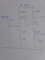
This is my actual circuit.
This is my actual circuit.
Attachments
Last edited:
The original Williamson design is carefully made, so if you are planning to build a real Williamson amplifier, you should stick to the schematic. The first two stages must be decoupled to ensure stability when feedback is applied. That's why the designer used a 33K resistor and a decoupling capacitor to drop the supply voltage to the input stage and isolate it from the the other stages.

If you're not planning to use feedback, then I suppose you can do anything you want. ;-) But if you are planning to add feedback, you should stick to the original design because it works best.
When you mention a 250 volts supply for the first stage, you may be referring to an "American" style Williamson, derived the "Musician's Amplifier" and used by Heathkit in their designs. This has a different decoupling scheme that results in a lower plate supply to the first stage. The two decoupling resistors (22K, 33K) here are in series, rather than in parallel like the original design. It also works, but it does reduce the headroom available to the first stage and results in slightly more distortion.
Last edited:

In the original circuit, the first stage has approximately 20dB less gain with feedback connected, so signal swing on the anode is much less during operation, and hence having a large signal swing is not a concern (although signal swing increases at very low and very high frequencies where feedback is reducing from nominal 20dB).
As indicated, it's the subtleties of power supply decoupling that may have significant performance consequences, along with subtle high frequency parasitic differences that cause gain and phase shift where they may not be welcome. Nowadays, LF stability can be maintained through other means, so maybe changing the decoupling is not such a concern, but caveat emptor. Similarly, high frequency stability is principally influenced by the output transformer, and first stage parasitics are likely to be second order effects.
Also note that final amplifier distortion is dominated by output stage valves, then driver stage valves, with input stage and PI stage valves a distant last, and mainly due to an increasing signal voltage swing from input to output.
See the rest of the circuits. The unbypassed cathode resistor is the feedback return point. It becomes part of the feedback voltage divider so it is necessary even though it provides some degeneration in the first stage. To minimize this degeneration, reduce the feedback network values. Then bypass whatever portion is needed to get the DC bias point right. Only needed or wanted if you want the increased OLG. Unbypassed rk also increases effective Ra by the same factor as it degenerates, so the reduction in gain is not always severe if the resistor in the plate is large.
Did a fault find on a sim amp some years ago and found the diff drivers 6SN7 joint cathode resistance of 390R is woefully low. 1K at least to see 7-8V on this point with 430-450V B+.
Very true, though 680 ohms is sufficient to greatly improve the performance of the driver stage.
Unless I'm mistaken, and perhaps Tim can chime in on this point, the common cathode on the driver stage is kind of key to the good performance of the Williamson, as is the common cathode resistance on the output stage. It's very tempting to "improve" upon the Williamson, but apart from the addition of stabilization networks and shifting the driver stage to a slightly more comfortable place, it really all works as designed and produces very low distortion.
That seems a bit of an "overkill", to drive standard KT,EL P-P stages when performance is limited by B+ & output tranny. High current class A drivers----just right to deal with that Miller effect with parallel P.P, with bandwidth advantages.
To find out, inject a 10 KHz squarewave at low power at the front end and have a look at the quality of the waveform at the secondary o/p tranny with nfb and with dummy load. That is a very stringent test. Very few amps can deal with this rocket test and yet many amp afficionados claim their amp sounds better than the others, until they see that test !
That amp I repaired used squat top round glass 5881´s;... In the early 1960´s was supposed to give 15%+ more power than the standard 6L6 class. Whether the original Tungsol spec remains for modern makes, I doubt it. One of the best sounding output tubes of it´s time was the 7027 especially for Hi Fi.
Good point. Any tube amp with global feedback needs to be 'scoped to determine its stability, especially the Williamson, which was very prone to oscillation without appropriate compensation measures. In addition to your test, an even more stringnet one is to dab some capacitance across the test load to see if that will cause any oscillation.
catalin gramada, before you go much further down this path, do you have an output transformer in mind? That's going to be the main key to building a Williamson. It must be well-made enough to handle the global feedback.
Lest anyone think this isn't worth the bother, I am somewhat fanatical about Williamsons and their exceptional musical qualities. ;-)
Talbot Wright recommended increasing the driver stage cathode resistance to 1k in 1962 [ https://dalmura.com.au/static/williamson_verstaerker.pdf ]. Imho Wright presented results that were in general sparse and subjectively presented. Whilst a cursory view of the driver stage loadline indicates improved headroom from increasing the cathode resistance, in practise the driver stage only approaches its swing limits when the output stage is dominating the distortion profile.Did a fault find on a sim amp some years ago and found the diff drivers 6SN7 joint cathode resistance of 390R is woefully low. 1K at least to see 7-8V on this point with 430-450V B+.
A few years ago I went through my collection of 6SN7 and 12AU7 and measured the variation in harmonic distortion coming out of the driver stage (with no gnfb) for 10Vrms output condition. As indicated by others, the 6SN7 clearly exhibited lower harmonic distortion levels than the 12AU7. For the 6SN7, the 2nd harmonic was by far the largest harmonic contributor, and the variation within my sample size of thirteen indicated tube swapping would be well worthwhile if distortion prior to the output stage was a concern. For one sample 6SN7, I compared driver stage output distortion for two cathode resistances of default 390R, and 680R, for output signal levels of 10V, 20V and 25Vrms, and found that the original 390R showed slightly lower 2nd H for all three output signal levels.
This indicates that well-meaning tweaks, and simulation results, may not end in a benefit and are best checked for results in-circuit.
catalin gramada, before you go much further down this path, do you have an output transformer in mind? That's going to be the main key to building a Williamson. It must be well-made enough to handle the global feedback.
Lest anyone think this isn't worth the bother, I am somewhat fanatical about Williamsons and their exceptional musical qualities. ;-)
No, it is not a such thing. I used a generic Hammond 2k Raa to drive 6 x kt66 triode strapped. Excellent stable from open loop to 15db nfb applied . I didn't bothered to inject more, it is already to tight with the speakers I have. Also didn't considered THD refinements, just looking to enjoy a hefty classic tube sound with enough power to shake some...Still a Williamson structure of circuit, I squeezed a little bit more output with the transformer I have ending with 60W rms, meant 20w per pair at 450V supply.
Last edited:
Talbot Wright recommended increasing the driver stage cathode resistance to 1k in 1962 [ https://dalmura.com.au/static/williamson_verstaerker.pdf ]. Imho Wright presented results that were in general sparse and subjectively presented. Whilst a cursory view of the driver stage loadline indicates improved headroom from increasing the cathode resistance, in practise the driver stage only approaches its swing limits when the output stage is dominating the distortion profile.
A few years ago I went through my collection of 6SN7 and 12AU7 and measured the variation in harmonic distortion coming out of the driver stage (with no gnfb) for 10Vrms output condition. As indicated by others, the 6SN7 clearly exhibited lower harmonic distortion levels than the 12AU7. For the 6SN7, the 2nd harmonic was by far the largest harmonic contributor, and the variation within my sample size of thirteen indicated tube swapping would be well worthwhile if distortion prior to the output stage was a concern. For one sample 6SN7, I compared driver stage output distortion for two cathode resistances of default 390R, and 680R, for output signal levels of 10V, 20V and 25Vrms, and found that the original 390R showed slightly lower 2nd H for all three output signal levels.
This indicates that well-meaning tweaks, and simulation results, may not end in a benefit and are best checked for results in-circuit.
That's really interesting, thanks!
A bit of a rabble here, but since we are dealing with Williamsons, if one can "see and build through Williamson problems", then one can build any amp.
Read on-
A modified Williamson front end using ECC83 paraphase phasesplitter i.e 3 stage amp was one version I built now 50 years ago and eventually sold; in fact nearly sim to the GEC 88-50 version that appeared during the 1960´s, but the global feedback loop (20dB) was modified with a step filter. There was also a LF rolloff interstage RC step filter between the paraphase outputs and the 6SN7 diff driver. The headache for many builders is that interstage step filter to make a compromise deal with LF roll-off and also not upsetting the amount of global feedback required to dampen the LS resonance point. So, we end up with a composite graph; the classic bath-tub feedback, THD and power curves. I used the same setup technique for my more recent dual 115W 6550 amp, and also dual 225W KT90 version both using SMPS B+power.
I can assure everyone, that using 150W rated output rannies that are flat to 15Hz to 40KHz each weighing 12kg (25Lbs), the low frequency end operation does become a serious issue with single frequency figures and power bandwidth must to be curtailed to avoid fuse blowing and overloading. I used a 3rd order steep signal cutoff Cheby filter on the input. One can go the other direction, avoid all that and that is increase/decrease the interstage LF roll-off cap values that the LF roll off is much higher (frequency wise); LF distortion willl rocket and bass will sound thin and LS will "honk" around resonance point as the global nfb runs out of gain.
To work the theory is far more complex using Cartesian polar & Bode plots, and still the Radiotron Hand book 4th ed page 371 (Learned, neg feedback section) does provide a ready formula but I found isn´t really applicable for todays wider frequency output transformers.
There are design tricks, but one needs sweep oscillator test gear, long persistent scope/or digital, and to be careful of not forcibly overloading the output stage with sub frequency signals when no screen resistors are used, that is below the output transformer cutoff point, when real power can damage. However, despite the stability optimization, it is still possible to drive the amp below the point of output tranny cut off where the transformer itself becomes saturated.
Bench Baron
- Home
- Amplifiers
- Tubes / Valves
- Williamson first stage question