Quick question please. I have couple of power resistors 10w cement encased type I toasted a bit with power dissipation almost on limit: 8-9w. I found there are permanently derated around 10 percent. Now as much as I known this are wire wound resistors but looking on datasheet t looks there are wire wound till 1K. Over this value they claims using "power film" whatever it mean. Can be this "power film" responsable for permanent damage in case of overheating please ? Thanks.
Did your zener testing also load the main output stage B+ supply to the point of clipping on-set ?
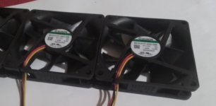
Yes it does. Usually 10-12 mA. There is a 1ohm sense resistor in the input who measure total current: screen + zeners. The last measurement I did with 73mA on screens shows 83 mA on input. It depend a bit by temperature by test when are bit cool it draw a bit more. With a cooler is the best I got 30C around on the case. I got a pack of 3 sunon 10mm flat fans but regulator work well also without it at 55C in normal position.


Last edited:
What is the anticipated load from the output stage B+ feeding the output transformer CT at clipping on-set? Won't that sag the B+, and hence also sag the screen voltage that is derived from that B+ via the zeners?
Yes it sag but insignificant 5-10v I remember. The PT I used have a 360V 1.5A ht secondary. Is huge brute force over 20lb piece. It drives 6x6550 into Ra-a1.9k at 480V without a hint. 36Vpk into 4ohm resistive load onset clipping 160W around.
Last edited:
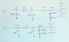
I instaled 1000uF capacitance bypassed by a high pulse multistrat 220nF/1.6kv. The ripple is less than 2mV. An analog voltmeter shows is exceptional stable. On power transients onset clipping the needle did not moving a fraction. The dynamic impedance of the diodes is not a problem at all.
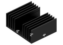
I'd suggest you need to find a similar product that has technical specs. If you then purchase a sample heatsink it may be in your interest to measure the thermal resistance with the fan in place, and applying heat generation at the point where your device will be located.
Thank. One more please: have two identical diodes wanna mount on same sink 180V/50w. I intend to mount it series connected. The diodes have anodes at the case. I can mount just one isolated and one directly with the case on sink ( the grounded end). Now, it will transfer a bit different due to mica washers used just for one of it. Do you see any problem with ? (electrical connection is not a problem, I just refer by series diodes working on different temperatures please-meant will be certain diferences in thermal derive and perhaps one will dissipate litle bit more than other...May I ignore this aspect in zener series connected please ? Can do a mica waher such a signifiant thermal transfer difference to count on series connection?). Thanks.
Last edited:
Perhaps if you identified the thermal resistance from diode junction to heatsink face, then added the thermal resistance for any insulator/washer, then added the thermal resistance of the heatsink to ambient, then multiplied that thermal resistance by the power being dissipated by the diode, and then added the ambient temperature, then tried to assess if the calculated diode junction temperature wasn't too high. Have you come across that type of thermal calculation during previous posts?
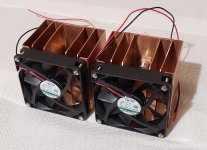
At 100mA with 12v fans supplied at 8v zener diodes get 35*C, more than enough...I used a pair of nte 180 V/50W, still the voltage is 190V over each diode due the tolerance suppose, but is very stable...
Last edited:
Why you guys hate NFB. The amp is built with NFB in mind. With NFB, the cathode of the 1st stage is somewhat bootstrapped. The grid voltage that the input tube sees is minimal. That ensure the low distortion.But the swing is minimal, I drived the amp with 200mVpk without nfb applied.
Last edited:
- Home
- Amplifiers
- Tubes / Valves
- Williamson first stage question


