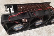
More, with a bit help of a 1.5w fan cooler zener temperature goes down to 32*C for 105 mA draw. Regulation is within 15V around meant less than 5 percent.I think the approach of using zenner diodes is wrong, they are sensitive when they heat up, there are other alternative solutions, have you thought about them?
That’s like running a mobile disco with a couple of Phase Linears. Fans required….
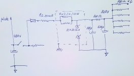
Hey Tim. I just followed you suggestion to try a choke input filter circuit for screens to see a difference. I quick wired the circuit with what I had on hand. Still the voltage are not quite I expected (should be 365x0.9 minus the voltage dropped to 100 ohm choke resistance, right ?). I put a random 15k resistor load to work as sink for ca 22mA current for 340V on screens. I.m not familiar with choke input filter, the ripple is about 120mVpk in actual configuration but there is a minimum current required to put the choke into linear region please ? Thanks.
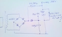

Last edited:
Yes, the old rules around using a choke input are not often discussed. There is a 'critical inductance', or minimum load, for which the choke regulates with little Vdc load droop - if the load current is too low, or inductance too low, then the output Vdc rises significantly (as can happen at initial turn-on with little to no Vdc loading). The background to that and a ripple-trap method to alleviate it is in the following link. https://www.dalmura.com.au/static/Choke measurement.pdf
Some discussion on that dual output scheme is in Section 5.6 of this linked doc: https://www.dalmura.com.au/static/Power supply issues for tube amps.pdf
The choke DCR may likely drop Vdc more than you may want (ie. from the anticipated 0.9x factor). The choke-input filtered load rail voltage can be nominally increased towards that of a capacitor input filtered rail (ie. 0.9 to 1.4x filtering factor) if required by adding some input filter capacitance - the Vdc level is quite sensitive to the value of added input capacitance, and PSUD2 is a good way to appreciate what is happening and what capacitor value may be a good start to use for testing. I've done that a few times with values up to about 1-2.2uF, but note that such a capacitor must be rated for high Vac as well as Vdc, so is likely a poly cap.
Thank You. Using a small input cap is very clever. I may imagine the minimum choke load will be determined by new input ripple level for a certain inductance..The choke I used is 4H, 150mA rated (still I thinking Hammond rated their chokes at 50cps...or maybe they rated it for power consideration...) so I may 'sink' 50mA at iddle leaving usable room of 100mA draw for the screens...or whatever it is before saturation occur.Thanks.
Last edited:
It seems the small input capacitor did not work well with nominal current. I did the following test: I used a 6.3K resistor for 50mA shunt load. The voltage was 315V without input cap and 350V with 1uF input cap. Then a 4.4K was wired in parallel for extra 70mA load. At 120mA the output voltage drops to 305V no mater with or without input cap meant with input cap the choke was not loaded enough, but suplimentary loading meant dropping voltage for a certain input capacitor...I will wire one more choke in series for 10H inductance. The choke I used are Hammond 158Q rated 5H 150mA/ 100ohm. They measured 5.7H and 5.9H at 100cps on my bridge.
Last edited:
Your choke DCR, and power transformer winding resistance will always combine to cause some droop in the output voltage with increasing load. Increase the input small capacitor's value until you achieve the required Vdc for the nominal load current - that may mean circa 2uF rather than 1uF.
But I don't appreciate why your loading for that rail (ie. screen current and perhaps preamps) would be in the range of 50-120mA ?
But I don't appreciate why your loading for that rail (ie. screen current and perhaps preamps) would be in the range of 50-120mA ?
There are only the screens who draw at max power, onset clipping 70mA at 350V so I expect to see a 7V potential difference on 100 ohm dcr of choke for 70mA draw. I did the test with power resistors. The choke was loaded permanent with a shunt for 50mA to work linear (to see a minimum permanent current), as permanent load. So from my actual input voltage I get 315V output without input cap and 350v output with 1uF in front. Then 4.4K shunt was added more to draw the same 70mA as sreen did. The output voltage drops to 305V around equal with or without input cap . So I get roughly 10V difference without input cap (315-305v) and 45v with input cap (350-305v) for same series dcr choke resistance for same 70mA diference please. Thanks
Last edited:
I think you are saying you did a test with 6k3 load for nominal 50mA load at 315V. Then another test with 2k6 load (6k3//4k4) for 120mA loading. Is that correct?
If so, then why are you testing at 120mA load when the screen feed has a max current requirement of 75mA at 350V ? I assume that is 75mArms, and not some peak level which may have a lower rms level?
If so, then why are you testing at 120mA load when the screen feed has a max current requirement of 75mA at 350V ? I assume that is 75mArms, and not some peak level which may have a lower rms level?
That because the screens grid curent is not consistent. Eg:at 350V screen draw 1.35mA at iddle and 12.5mA onset clipping x 6pcs mean roughly total 8mA iddling and 75mA max please.
50mA was a permanent shunt to keep the choke in linear region. With 25mA permanent shunt the output voltage is 340V around meant the choke is too small for such current.
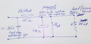
50mA was a permanent shunt to keep the choke in linear region. With 25mA permanent shunt the output voltage is 340V around meant the choke is too small for such current.

Last edited:
The current drawn from a common supply rail needs to be seen and measured as an average, as half the screens could have a max current requirement at the same time as the other screens draw less than their idle level. As such, your idle current summation is fine, but I am concerned about how you determined 12.5mA per screen for a max signal condition.
Even if total screen current reached 75mA rms (eg. say 70mA constant total for three screens at full conduction of a squarewave, and 5mA constant total for the three screens not conducting), then why are you trying to test at 120mA loading?
Or were you saying the 4k4 load test was just with 4k4 loading, and not with 6k3 in parallel?
The screen curent was determined by 100ohm grid stoppers I have and one 1 ohm series sense resistor on screen supply rail with sine wave at full power onset clipping
I just mentioned If the screens draw at iddle 8mA so the choke work with 8mA only the output choke is not functional as choke input filter. It need a minimum current tghrough and this is not 8mA but 50mA more for the choke I have. I tried with 22mA shunt and the output is 350V.With 50mA shunt it goes to 315V as should be...Input voltage is more 350VAC (mains vary).
So my choke need a minimum current through to work as a proper input choke filter, that is 50mA permanent used for. The iddling screens did not draw such of current and in consequence the voltage depend by ac ripple the filter seen.
With a bigger choke (say double) the minimum current will be less but still don't see it working with 8mA through..maybe a 20H or so...
Last edited:
I just roughly measured again with the amp dimmed : I got 73mA total draw by screens (7.3V on 100ohm resistors in screens filtering stage) and 1.1V on 100ohm screen grid resistor on one socket - I suppose there are not all equal current draw. At 356V. This is not with choke input filter, just a roughly measurement with old supply circuit to confirm the currents screens draw at a certain voltage at actual mains. The 1 ohm sense resistor is not usable , is on input and shows the total current including the current zeners draw (10-12mA) so I measured the current on 100ohm resistor in output filter stage.
Last edited:
Even if total screen current reached 75mA rms (eg. say 70mA constant total for three screens at full conduction of a squarewave, and 5mA constant total for the three screens not conducting), then why are you trying to test at 120mA loading?
Relative to a minimum current I found a formula in Patrick Turner material: minimum inductance L = (Vout / minimum current) /900 meant in my case for 8mA at 330V =46H and 6.3H for a minimum current of 58 mA (50mA bleed current + 8mA screens iddling ). My 5.9H choke it is almost spot on. So for the 5.9H choke I used 60mA is a condition whilst total 130mA is a consequence of max current draw.
Last edited:
Imho the 100R in the common feed is the dc voltage to measure to give total average current drawn from all screens, as it is placed between two large filter caps, so will have no Vac across it of any significance. So up to 73mA for total screen requirement is the nominal target for 360Vdc feed. Yes there will be some variation between screens, but as the per screen dissipation is circa 4.4W then there should be no significant concern as long as the cathode currents are balanced between the 6x tubes, and suit plate dissipation limits.
From that, my concern is that the load current range is from circa 8mA to 73mA, so approaching 10:1, which is beyond what most choke supplies are likely to be capable of whilst maintaining acceptable performance. That may need a swinging choke, and ripple trap filter, and some compromise on your ideal of what voltage variation you can allow.
A guess at your parts in PSUD2 indicates 350Vdc with 73mA load and 2uF cap in front of a 6H choke of 100R DCR, but I don't know the power transformer winding resistances or voltage that you have. With 40mA load the Vdc rises to 390V, and down to 10mA the Vdc would rise towards 450V.
If you were ok with a lower Vdc at 73mA then use a lower input cap such as 1uF where Vdc gives 350V for 27mA, but Vdc falls below 300V for load current approaching 70mA.
You also have the option to resonate the choke, and an option to lower the inductance (eg. use both your chokes in parallel for testing) to see how that affects your levels. PSUD2 indicates a 3H 50R choke would give 330V at 73mA with 2uF input cap, and rising to 370V at 40mA load - so not as much voltage rail variation. But using a lower inductance is likely to need a ripple trap filter to keep operation above critical level, and you still aren't down at 10mA idle level.
However note that screen current requirement for idle through to clipping on-set will vary with Vdc feed. If you set your idle at high Vdc then is that a compromise for the amp when the screen voltage varies under load. That would happen with a zener drop approach as well, due to main B+ sag between idle and clipping on-set.
Well still the Zener approach gaved me the best regulation till now. With roughly 90mA regulator the screen voltage vary between 380v iddling (mostly by diodes voltage derating at 60*C) to 360V at max current screens draw. With a cooler the regulation get better to 10v around. Ok, plus one volt over 100 ohm screen grid resistor.
The test was done with the chass upside down so zeners did not benefit by proper cooling (over 30C in the proximal environment)
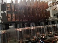
The test was done with the chass upside down so zeners did not benefit by proper cooling (over 30C in the proximal environment)

- Home
- Amplifiers
- Tubes / Valves
- Williamson first stage question
