Welcome to my fist thread.
during the last few weeks i've been reading about discrete amplifier designs, for example Blameless and wolverine, and was looking for a challenge to design my own high end amplifier. but with a twist to make it challenging and unique. that's when i came to the following thread: https://www.diyaudio.com/community/threads/mosfet-audiophile-amplifier-with-opa-driver.341751/
I decided to take on the challenge to design an amplifier with an op amp input and gain stage while being high end.
the following limitations are put in to place to make the challenge of design more difficult:
so you can find my concept in the attachments. you also can find the analyzer settings there.
i hope you all have some input to improve it even further or learn something from my concept.
thanks to these members for their contributions to this project:
Mark Tillotson
steveu
xrk971
Best regards,
ImpatientIcecream
during the last few weeks i've been reading about discrete amplifier designs, for example Blameless and wolverine, and was looking for a challenge to design my own high end amplifier. but with a twist to make it challenging and unique. that's when i came to the following thread: https://www.diyaudio.com/community/threads/mosfet-audiophile-amplifier-with-opa-driver.341751/
I decided to take on the challenge to design an amplifier with an op amp input and gain stage while being high end.
the following limitations are put in to place to make the challenge of design more difficult:
- the input and voltage gain has to be done by op amps
- a minimum avg. power of 100W with an 8 ohm load.
- minimum gain of 20.
- "wolverine" like performance regarding THD.
- minimum of 2 mV ripple on PS rails.
- maximum of two output devices to keep the design tiny (optional if large improvements can be made).
so you can find my concept in the attachments. you also can find the analyzer settings there.
i hope you all have some input to improve it even further or learn something from my concept.
thanks to these members for their contributions to this project:
Mark Tillotson
steveu
xrk971
Best regards,
ImpatientIcecream
Attachments
Last edited:

Interesting - does performance degrade without follower U8? If you drive each driver base via a resistor || capacitor you'll have more symmetrical drive. And the caps act as a speed-up cap too. Might want a CCS at the +ve rail too though - perhaps your way is simpler.
Without bootstrapping the second opamp you'll probably have limited headroom due to the LME49860 not being rail-to-rail, and the drop in Q3 and Q4.
Without bootstrapping the second opamp you'll probably have limited headroom due to the LME49860 not being rail-to-rail, and the drop in Q3 and Q4.
have tried but with no success of working at all. the function of follower U8 is to lower the loading of the opamp, thus improving the performance. i also tried using diodes as biassing circuit and BJT output without buffer and CCS, but this would load up the opamp weirdly and causes more instability.Interesting - does performance degrade without follower U8?
i'll try, which values should i start with?If you drive each driver base via a resistor || capacitor you'll have more symmetrical drive.
do you mean like this?Without bootstrapping the second opamp you'll probably have limited headroom due to the LME49860 not being rail-to-rail, and the drop in Q3 and Q4.
Last edited:
No, capacitively bootstrapped from the amp's output so it can swing outside the rails and have no headroom limitation
i found this picture in one of your posts: https://www.diyaudio.com/community/threads/nic-opamp-vas-topology.348646/post-6224670
is the bootstrap R23, C8, R7 D9 and D10?
The TTX004B are bjt which are not standard in LTspice. Search for them with "LTspice model" behind their name on Google and add them to the "standard bjt" file on the appdata folder of LTspice. Search for adding bjt to LTspice if you need more info.When opening the asc-file from the first post LTspce complains about missing symbols:
TTA004B
TTC004B
THD_Analyzer
The THD_analyzer is an addon. Search for it on this forum. Its useful for plotting thd graphs
I tried to fix simulation issues but the OP will have to provide the rest, including .lib LME49860.sub . The "analyzer" has a "Notch" pin, which I dunno what to do with so I just grounded it. I autogenerated the analyzer symbol??
I see ~4 places where voltage swing is lost so it's going to clip way short of the rails. Bootstrapping an op-amp taxes the input common-mode range. LV has done a couple interesting designs that use positive feedback to reduce the input voltage range. It requires a defined impedance source, from a grounded stage. I favor a CFP output with gain that boosts the +/-15V range up to the power supply rails. The biggest issue using op-amp IPS is compensating ~two dominant poles.
I see ~4 places where voltage swing is lost so it's going to clip way short of the rails. Bootstrapping an op-amp taxes the input common-mode range. LV has done a couple interesting designs that use positive feedback to reduce the input voltage range. It requires a defined impedance source, from a grounded stage. I favor a CFP output with gain that boosts the +/-15V range up to the power supply rails. The biggest issue using op-amp IPS is compensating ~two dominant poles.
Attachments
No such thing as "Watts RMS".
Volts RMS multiplied by amps RMS cannot equal an RMS number. (V x I = watts).
RMS = Root Mean Square and if you multiply the square root of 2 by the square root of 2 you obtain just the number "2". There is NO MORE square root involved.
Volts RMS multiplied by amps RMS cannot equal an RMS number. (V x I = watts).
RMS = Root Mean Square and if you multiply the square root of 2 by the square root of 2 you obtain just the number "2". There is NO MORE square root involved.
i agree. from now on i'll call it "average power"No such thing as "Watts RMS".
I have tested the bootstrapping of the opamp. It works pretty good in terms of stability and THD, but is limited to +-36V output voltage.bootstrapping the second opamp
I don't know why it is limited, but i suspect it has something to do about the input common-mode range.
I'm going to try the CFP OP with gain and post an update when ready.
PS: thanks for all the replies, it helps a lot.
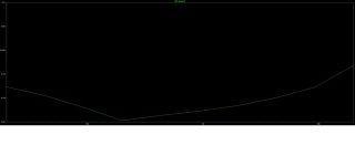
I tested the bootstrapping some more and found that the breakdown voltage of the zener diodes and the limited input common-mode range were limiting the voltage swing. By changing the breakdown voltage to 20V (LME49860 can handle +-22V) reaching 80V p-p (100W average power @ 8 ohm) was possible.
After testing with a single op amp to generate all of the gain, it already clipped at 64V p-p. when adding an opamp in front, which shares the total gain, the 80V is reached without clipping. this proves that the bootstrapping reduces maximum voltage swing by reducing input common-mode range.
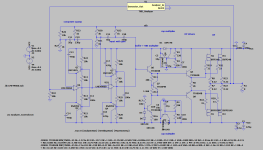
this resulted in the following circuit:

feel free to roast my circuit!
After testing with a single op amp to generate all of the gain, it already clipped at 64V p-p. when adding an opamp in front, which shares the total gain, the 80V is reached without clipping. this proves that the bootstrapping reduces maximum voltage swing by reducing input common-mode range.
this resulted in the following circuit:
feel free to roast my circuit!
Historically, "Watts RMS" referred to an undistorted sine wave output, as opposed to things like "peak music power" and other marketing hype that used various rational to excuse exaggerating the power of audio equipment. Early solid-state amplifier ratings were often hopelessly optimistic, partly due to the poor understanding of device power ratings based on Tc=25C and BJT SOA limitations.No such thing as "Watts RMS".
Volts RMS multiplied by amps RMS cannot equal an RMS number. (V x I = watts).
RMS = Root Mean Square and if you multiply the square root of 2 by the square root of 2 you obtain just the number "2". There is NO MORE square root involved.
I have been working on the amplifier design.
The following changes have been made:
what kind of improvements can be made to lower THD?


The following changes have been made:
- Removed the OP drivers
- Simplified bootstrap and VBE circuit
- Simplified supply for U2
- Improved feedback ratio to improve clipping performance (U2 clips first)
what kind of improvements can be made to lower THD?
Bootstrapping an opamp always implies some change of latching when driven hard. I'd prefer a voltage amplifier following the opamp output, see e.g. the designs in the RCA Power Transistor Handbook.do you mean like this?

Best regards!
thank you for your reply!Bootstrapping an opamp always implies some change of latching when driven hard.
Correct me if im wrong: latching is the phenomenon where the output devices keep conducting while this is not wanted and caused by input overload.
Then the following question arises: when U2 (referring to the schematic in my latest post) clips first, does is prevent U7 to get overloaded by the input signal thus prevents latching?
To stay within the scope of this challenge, when U2 does not prevent latching, how can we prevent it while using opamps for all of the gain?
- Home
- Amplifiers
- Solid State
- >100W opamp based amp