The bootstrapping is being done by capacitors. AC coupling will lead to poor behavior at some low frequency.
I think that bootstrapping needs DC coupling. Additional supply rails will help.
Ed
I think that bootstrapping needs DC coupling. Additional supply rails will help.
Ed
Update
After researching op-amp latching i found the following situations where latching can occur:
I'm still looking for a solution for the latching by output voltage higher than positive or lower than negative rail.
Maybe i should be less stubborn and try the design of Mark Tillotson, regarding the bootstrapping of the op-amp and latching.
Thoughts and tips are welcome!
After researching op-amp latching i found the following situations where latching can occur:
- Input voltage higher than positive rail or lower than negative rail (some op-amps latch before crossing the positive or negative rail).
- Output voltage higher than positive rail or lower than negative rail (some op-amps latch before crossing the positive or negative rail).
- During startup and shutdown.
- During a dip in mains voltage (when using a passive power supply).
- During hard loading when op-amp is bootstrapped.
I'm still looking for a solution for the latching by output voltage higher than positive or lower than negative rail.
Maybe i should be less stubborn and try the design of Mark Tillotson, regarding the bootstrapping of the op-amp and latching.
Thoughts and tips are welcome!
Chevin 3000a amps have similar topology but use transnova output configuration.View attachment 1274592
i found this picture in one of your posts: https://www.diyaudio.com/community/threads/nic-opamp-vas-topology.348646/post-6224670
is the bootstrap R23, C8, R7 D9 and D10?
true, but is in bridged mode. the opamps are limited to their normal maximum and minimum rail voltages. Z3 and Z10 limit the rail voltages to +-15VChevin 3000a amps have similar topology but use transnova output configuration.
That topology drives the floating supply rails so you cannot run two channels on the same power supply. QSC uses a single voltage with no center tap so that the speaker is DC protected by the supply filter caps.
Check out this thread:
https://www.diyaudio.com/community/...ent-without-really-trying.263065/post-6047229
2nd op-amp is bootstrapped.
https://www.diyaudio.com/community/...ent-without-really-trying.263065/post-6047229
2nd op-amp is bootstrapped.
Yes, but the output stage has voltage and current gain so less voltage swing is needed. About as simple an amp as it gets, sounds great and puts out serious power.true, but is in bridged mode. the opamps are limited to their normal maximum and minimum rail voltages. Z3 and Z10 limit the rail voltages to +-15V
View attachment 1287586
Also, Chevin uses a limiter to keep it from blowing up.
sounds amazingly nice to optimize and diy! maybe i will give it a try with a modern op-amp like OPA1655 or LME49860.Yes, but the output stage has voltage and current gain so less voltage swing is needed. About as simple an amp as it gets, sounds great and puts out serious power.
thanks for sharing! at post 68, https://www.diyaudio.com/community/...ent-without-really-trying.263065/post-6049485Check out this thread:
https://www.diyaudio.com/community/...ent-without-really-trying.263065/post-6047229
2nd op-amp is bootstrapped.
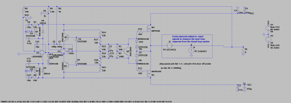
Elvee talks about having difficulties using a single bootstrap network for the op-amp and the drivers instead of two. while looking at the differences of my design and his, i came up with the following:
One of the problems, i think (I'm just a mechanical engineer, just trying to understand the world of electronics 😅), with bootstrapped op-amps is the phase delay between the output of the op-amp and the output stage of the complete amp (where the rails are bootstrapped from), especially at high frequency. To solve this i made a design which bootstraps the op-amp from the output of the op-amp while simultaneously providing current to the VBE (and not using drivers). This would in theory avoid phase delay between op-amp output and bootstrap signal.
the design still uses U3 early clipping to control CM range and swing limitations which both can result in latching.
secondly, i changed from LME49860 to OPA1611, because of the power dissipation limitation of the two channel LME op-amp. so going to "dual mono" will be sufficient.
also, the op-amp rails move nicely at the maximum designed voltage swing.
finally, i'm really happy about the THD performance 😄
What tools should i order to build and test the prototype?Are you planing to build a prototype?
The tools i already have:
- soldering kit
- DMM
For the oscilloscope, i'm thinking about a PC based PicoScope.
Tips and suggestions are appreciated!
The minimum required tools are the soldering equipment, DMM, signal generator, oscilloscope, and dummy load.
A power supply is convenient for low-power circuits, but one capable of powering an amplifier will be expensive. Using the amplifier's own supply is a no-cost option.
Distortion analyzers have only recently come down in price. They are still somewhat expensive for a hobbyist.
Ed
A power supply is convenient for low-power circuits, but one capable of powering an amplifier will be expensive. Using the amplifier's own supply is a no-cost option.
Distortion analyzers have only recently come down in price. They are still somewhat expensive for a hobbyist.
Ed
Bench power supply with current limiter is really useful when testing unstable/oscillating amps, and it helps to avoid frying transistors during testing.
That's the one I'm using:
https://www.tequipment.net/TTi/CPX200D/DC-Power-Supplies-/-Lab-Power-Supplies/
I paid for it half of current advertised price, back in 2018.
That's the one I'm using:
https://www.tequipment.net/TTi/CPX200D/DC-Power-Supplies-/-Lab-Power-Supplies/
I paid for it half of current advertised price, back in 2018.
update
Thanks for your comments on the tools related question!
I'm going to order the tools this week, but i don't have much time to set up a test in the next couple of weeks. So don't expect a test result soon.
loop gain
I recently uploaded my personal discovery (probably not the first one to try this) on bootstrapping an op-amp without using the output of the amplifier. I found a weird feature of this bootstrapping method. It keeps a "more normal" phase margin and gain margin than with normal bootstrapping. While experimenting with a composite layout, i came across the following: while using composite layout and the standard way of bootstrapping (from the output of the amplifier with large caps), the loop gain plot looks weird. Like the phase starts at 100 deg, rises to 250-ish and goes back down, but doesnt go to minus 180 and beyond like usual. also the loop gain is not what i expected from composite.
Is the circuit with the normal bootstrapping stable according to the simulation (i know it isn't the real world)?
PS i'm not going to try the composite layout in the real word as a first try. lets try to make a working amp first 😅


When looking at the loop gain plot of a composite layout, while using the new bootstrapping method, i get a more normal loop gain: high loop gain like expected from a composite layout and a more normal phase plot.


Thanks for your comments on the tools related question!
I'm going to order the tools this week, but i don't have much time to set up a test in the next couple of weeks. So don't expect a test result soon.
loop gain
I recently uploaded my personal discovery (probably not the first one to try this) on bootstrapping an op-amp without using the output of the amplifier. I found a weird feature of this bootstrapping method. It keeps a "more normal" phase margin and gain margin than with normal bootstrapping. While experimenting with a composite layout, i came across the following: while using composite layout and the standard way of bootstrapping (from the output of the amplifier with large caps), the loop gain plot looks weird. Like the phase starts at 100 deg, rises to 250-ish and goes back down, but doesnt go to minus 180 and beyond like usual. also the loop gain is not what i expected from composite.
Is the circuit with the normal bootstrapping stable according to the simulation (i know it isn't the real world)?
PS i'm not going to try the composite layout in the real word as a first try. lets try to make a working amp first 😅
When looking at the loop gain plot of a composite layout, while using the new bootstrapping method, i get a more normal loop gain: high loop gain like expected from a composite layout and a more normal phase plot.
That is a sign of latch-up. Spice found a DC operating point that is not the intended one! The "poor behavior at some low frequency" in my post #21 includes DC.ImpatientIcecream said:Is the circuit with the normal bootstrapping stable according to the simulation (i know it isn't the real world)?
Ed
Update
I have been building my speakers for a while and they are done for now. so i got time again for the amplifier.
the speakers can be found here
i have a question about the Vbe multiplier:
Do the parallel resistors (R15 and R16) have any effect on the thermal compensation of the output stage?
if yes, can the circuit provide adequate thermal compensation?
Attachments
Based on a modified simulation, you are clipping well short of the rails, especially on the positive side due to the MOSFET bias offset, and the 2x limitation of the bootstrapping. Bootstrapping an op-amp stresses the input common mode range, which may not be simulated well. Adapting an op-amp limitations to high voltage leads to a lot of problems. I wouldn't bother considering it also compromises performance.
- Home
- Amplifiers
- Solid State
- >100W opamp based amp