Hi,
I have a set of second hand KT120 Push Pull Parallel mono blocks that are made by a boutique amplifier builder that I'd like some help with.
The amps are 6sn7 paraphase (I think) feeding parallel 6sn7 driving the parallel kt120's @ 430v with a bias current of 120ma for the pair. Power section is dual GZ34/5AR4 CLC with another RC section for the small tubes.
I initially took them to my amp tech due to blown screen resistors and low heater voltages. He replaced the screen resistors with 1k higher wattage types and managed to get a bit more voltage for the 6SN7 input and driver tubes by using Schottky's for the DC heater voltage. The KT120 and GZ34 heaters were low but within 6% for the KT120 and 7% for the rectifier.
But when tested they were only putting out 60.6W, they basically clipped then stopped. The B+ at "full" power was good, no major sag. The original specs for the amps were 120W, which seems reasonable for a set of KT120 in PPP.
Contacting the manufacturer, he mentioned they were wound for high West Australia voltages - like 240-250vac, and in NZ where the voltage is usually 234v-236v which explains the low heater voltages, but he was stumped on the power output. He offered to wind new power transformers which was a really good offer.
Unfortunately, after fitting the new transformers the heater voltages were way too high (could be resolved with dropping resistors) but the power output was still the same.
My tech thought that perhaps the OPT impedance was way too high, but also declined to work on the amps any further - too heavy for him. I checked the OPT impedance by putting ~6v AC into the secondaries, measuring the voltage on the secondaries and calculating the turns ratio, squaring, then dividing by the nominal tap tested. The 4 ohm was around 2500ohms and the 8ohms 3000ohms, which is not stupid high.
I have traced out the amp and drawn the schematic, attached. This is the first time I've fully traced a power amp, and the first time using LTPsice, even to draw a schematic. Drawing the schematic vertically seemed to reduce the amount of lines crossing, so sorry if it's not the usually left to right 🙂 Might be some other schoolboy errors in there. I modelled the PSU section with PSUD, and used a model for the dual GZ34/5AR4.
The 6SN7 stages seem to have really high anode load resistors and operating points, and if I'm drawing and reading the load lines correct for the driver tubes, do not have the ability to supply enough voltage swing to the power tubes.
I've got a bunch of questions, but to begin with if anyone could help check my assumption on the driver stage, for voltage swing capabilities, if I got the existing load lines correct, if I'm reading the voltage swing correct and whether my suggested changes would work better. I used the Amp books load line calc and also their instructions for parallel tubes, which is to double the Anode resistor to model correctly and when wiring the parallel tubes, to half the shared cathode resistor value so each triodes current remains the same as modelled.
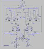
2nd pic is the factory driver load line. I doubled the 68k load to 136k and selected a point that matched the cathode voltage - gave a current of 1.75ma, which is about twice the calculated current through the driver anode. I read that the 0v line gave the voltage swing (correct?) so 25v = 50vpp? The Power tubes are biased at -51.5v for 120ma for the parallel kt120 pair, so am I correct the driver stage could only deliver half the required voltage for the power tube swing = half power @ only 60w?
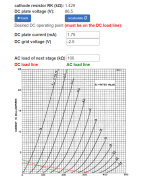
Would the 3rd pic be a better operating point? Using a 15k anode load, (modelled at 30k same instructions from amp books) biased at -6v giving 5ma current with a RK of 1.2k and 0v line at ~75v. If soldered I would half the 1.2k to ~600ohm.
thanks Bert
I have a set of second hand KT120 Push Pull Parallel mono blocks that are made by a boutique amplifier builder that I'd like some help with.
The amps are 6sn7 paraphase (I think) feeding parallel 6sn7 driving the parallel kt120's @ 430v with a bias current of 120ma for the pair. Power section is dual GZ34/5AR4 CLC with another RC section for the small tubes.
I initially took them to my amp tech due to blown screen resistors and low heater voltages. He replaced the screen resistors with 1k higher wattage types and managed to get a bit more voltage for the 6SN7 input and driver tubes by using Schottky's for the DC heater voltage. The KT120 and GZ34 heaters were low but within 6% for the KT120 and 7% for the rectifier.
But when tested they were only putting out 60.6W, they basically clipped then stopped. The B+ at "full" power was good, no major sag. The original specs for the amps were 120W, which seems reasonable for a set of KT120 in PPP.
Contacting the manufacturer, he mentioned they were wound for high West Australia voltages - like 240-250vac, and in NZ where the voltage is usually 234v-236v which explains the low heater voltages, but he was stumped on the power output. He offered to wind new power transformers which was a really good offer.
Unfortunately, after fitting the new transformers the heater voltages were way too high (could be resolved with dropping resistors) but the power output was still the same.
My tech thought that perhaps the OPT impedance was way too high, but also declined to work on the amps any further - too heavy for him. I checked the OPT impedance by putting ~6v AC into the secondaries, measuring the voltage on the secondaries and calculating the turns ratio, squaring, then dividing by the nominal tap tested. The 4 ohm was around 2500ohms and the 8ohms 3000ohms, which is not stupid high.
I have traced out the amp and drawn the schematic, attached. This is the first time I've fully traced a power amp, and the first time using LTPsice, even to draw a schematic. Drawing the schematic vertically seemed to reduce the amount of lines crossing, so sorry if it's not the usually left to right 🙂 Might be some other schoolboy errors in there. I modelled the PSU section with PSUD, and used a model for the dual GZ34/5AR4.
The 6SN7 stages seem to have really high anode load resistors and operating points, and if I'm drawing and reading the load lines correct for the driver tubes, do not have the ability to supply enough voltage swing to the power tubes.
I've got a bunch of questions, but to begin with if anyone could help check my assumption on the driver stage, for voltage swing capabilities, if I got the existing load lines correct, if I'm reading the voltage swing correct and whether my suggested changes would work better. I used the Amp books load line calc and also their instructions for parallel tubes, which is to double the Anode resistor to model correctly and when wiring the parallel tubes, to half the shared cathode resistor value so each triodes current remains the same as modelled.
2nd pic is the factory driver load line. I doubled the 68k load to 136k and selected a point that matched the cathode voltage - gave a current of 1.75ma, which is about twice the calculated current through the driver anode. I read that the 0v line gave the voltage swing (correct?) so 25v = 50vpp? The Power tubes are biased at -51.5v for 120ma for the parallel kt120 pair, so am I correct the driver stage could only deliver half the required voltage for the power tube swing = half power @ only 60w?
Would the 3rd pic be a better operating point? Using a 15k anode load, (modelled at 30k same instructions from amp books) biased at -6v giving 5ma current with a RK of 1.2k and 0v line at ~75v. If soldered I would half the 1.2k to ~600ohm.
thanks Bert
Attachments
-
 kt120 ppp schematic.png48.4 KB · Views: 460
 -
 327-136k(68k-1k) -2.5v 1.75ma (x2 measured 3.5ma) - 50vpp - factory driver.png106.4 KB · Views: 379
 -
 327-30k(15k-1.2k) -6v 5ma - 160vpp - same voltage Bert.png110.5 KB · Views: 208
 -
 factory psu - close.png2.7 KB · Views: 212
 -
 factory psu.png140.4 KB · Views: 377
Last edited by a moderator:
You could try R12 and R17 33K rather than 68K. It will drop the gain, but at 79V plate there's not really enough swing to fully drive the KT120.
Thanks, good to have some confirmation. Yeah the plate voltage is real low, I have 33k available to try. As is, the amp needs .5v to get the 60w, so ~1v for full power if I can get enough swing, losing some gain would be ok.
Does anyone know what the cathode connection to the OPT is on the driver tubes, R18 and R19? Some sort of feedback?
Since there isn't a connection shown on your schematic, my guess is some sort of balanced feedback from the secondary.
Yeah tracing just has wires going into the OPT so no idea where they actually were connected. Thanks

The output transformers are wound by the builder and don't have any taps or identification on the wire colors unfortunately. The GNFB loop is a really small amount of feedback, so makes sense there is other feedback in play. Thanks.
Next question(s). The operating point for the 1st stage 6SN7 look like they are right on the nonlinear portion of the curves, if I changed the operating point to something more standard - i.e 47k anode load to get in the linear portions of the curves would the resistor dividers for the second triode need to be changed as the gain has changed? i.e. keep the AC signal from both anodes equal.
If that 1st stage is a paraphase?
The amp does have a bit of hum - 4-6mv from the 8 ohm taps - not terrible but audible on sensitive speakers. The grounding looks good on the amp, and moving the output transformer around doesn't help either. So I am suspecting it's the phase split not being equal. I've read that paraphase for hifi is better if a variable resistor is used to get the signals to match precisely. If correct, where would I place a variable resistor?
I'll be doing an AC measurement on Thursday to see if my hunch is correct.
Last edited by a moderator:
Sorry, I was reading another thread at same time as this one and got the Peerless transformer mixed up.

I guess your tech was right regarding the OPT primary impedance. A plate to plate load of 3 k, when fed from 430 Vdc, might easily be driven by just one pair of KT120's and put out about 60 W. The power can't be significantly increased by doubling the tubes count. What's the power you get at a 4 ohms load connected to the 8 ohms tap?
The cheapst way to increase the power somewhat (!) is to replace the GZ34 rectifiers by SS diodes.
Best regards!
The cheapst way to increase the power somewhat (!) is to replace the GZ34 rectifiers by SS diodes.
Best regards!
Its just the biasing on the plates was low making me think maybe the design was for 6sl7. If you change for ltspice for 6sl7 do the load lines look more reasonable? just wondered if it started as 6sl7. With 6sn7 there would be no need to parallel tubes for the driver, but with 6sl7 it would.
Thanks Kay I'll be at a friends where we can test power output tomorrow. Will try 4ohm load from the 8ohm tap before making any changes and post the results.What's the power you get at a 4 ohms load connected to the 8 ohms tap?
I haven't got the LTSpice model working, was just using to create the schematic, might take me a while to work out how to actually model 🙂 I was doing the load lines from the Amp Books calculator. The setup does look more suitable for a 6SL7 for sure.If you change for ltspice for 6sl7 do the load lines look more reasonable?
- Home
- Amplifiers
- Tubes / Valves
- KT120 PPP Issues/Improvements