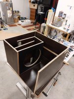
I'm going through a phase in my life when I want to design 3-way conventional box speakers with large (10" or 12") woofers and large midranges, where the midrange will almost have LF extension to act as the midbass in 2-way designs. Having loved
the Darbari which I had since 2014, I now want to see if I can make them smaller, perhaps with less expensive crossovers, and better.
So, on this journey, I realise I am hesitant to design a passive crossover at, say 100Hz to 250Hz, which is where my crossover between midrange and woofer will happen. I am afraid the coils and crossovers will be large, and even hard-core fans of passive crossovers seem to be happier doing this one part active, and driving the woofer with a separate amp channel. I'm thinking of doing (at least) the same, so I need a 2-way active crossover.
I want to use something which I can embed inside the speaker, throw in the mains PSU and two amp channels, and basically make the speaker a standalone, powered active speaker. I'll be happy to do a passive xo between mid and tweeter. I've worked with difficult passive crossovers for the
Asawari 4 and
Asawari 5, so I feel more confident now that I'll be able to do a decent job there even with fairly difficult drivers. What I need active for is just the low-frequency split between mid+tweeter on one side and woofer on the other.
I've worked with MiniDSP hardware (the Darbari runs on the 4x10HD), but I balked at the idea of using a 2-in 4-out box (their smallest) for my simpler 1-in 2-out requirement. I am hoping that any active analog crossover I design will be as clean but less expensive than their 2x4HD. The 2x4HD would have made me invest USD 200 per speaker enclosure -- I'm hoping my module will be much less expensive. Also, KiCAD has become really powerful, so I thought I'll just wing it. Make my own. Fabbing a prototype PCB is also super-easy these days -- I use
PCBPower with super results.
Studies
Most of my learning is from Don Lancaster's Active Filter Cookbook and Doug Self's Design Of Active Crossovers. Linkwitz' website. Rod's ESP pages. Randy Slone's Audiophile Projects Sourcebook. Plus years of trickle-down learning from everyone. I missed Bob Ellis' active xo project and group buy which happened 15 years ago, so I didn't learn much from there. I found the PDF of their builder manual online recently, but it wasn't very clear without a PCB on hand. Doug Self's book is the most useful.
No allpass filters
In my studies, the biggest difficulty I have faced is in understanding the use of allpass filters. When Linkwitz says "there's no point in designing an accurate crossover unless you also correct the delay", you tend to sit up and dig deeper to figure out just what problem he's fixing. This is one piece which doesn't show up in passive xo designs, so I never learned about them in my previous speaker designs, all passive. So I studied all I could find, took my final set of confusions to
this thread, processed the helpful answers, and concluded that if I design active xo the way I have been designing passive xo, I don't need allpass filters. So, my circuit will not have provision for any.
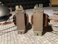
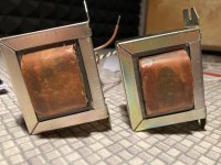
Powering from power amp rails
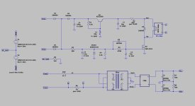
I'll design the board to take AC from the secondaries of the transformer. I'll have one toroid per speaker enclosure, and this will have high(er) voltage secondaries, because they'll power the power amp channels. I'll avoid asking for a separate pair of windings just for my xo -- I'll do a voltage dropper after the bridge, on my board, and feed its output to the voltage regulator ICs. A voltage dropper is just a TO220 transistor, a zener, some R and C per rail.
Rod Elliot's pre-regulator supplies the basic idea.
SMD 4-opamp chips
I took a deep breath and decided to bite the bullet and go with 4-opamp chips. My simple 2-way already requires 9 opamps it seems. Placing 5 dual-opamp chips seems just too messy in this day and age. Since many of the best chips in this category are only available in SOIC-14 and TSSOP packages, I'll provide for those SMD footprints on the PCB, and will also provide for 14-pin DIP pads so that people can do opamp rolling using SOIC-14 to DIP adapters. I personally do not have appetite for opamp rolling. If no one tells me otherwise, I'll go with OPA1604 4-opamp chips. If my opamp count remains at the current 9, I'll use two 4-opamp chips and one dual-opamp LM4562 DIP-8 chip.
SMD capacitors?
I'm not comfortable soldering SMD parts, but I think I'll use SMD for the filter capacitors, because the through-hole high quality box capacitors can be as large as 13mm x 6 mm, which is really too big when I'm going to use so many of them. So I'm thinking of using 1206 SMD footprints, the biggest there is in SMD.
Many capactors, all resistors and other components will be through hole.
The filter blocks themselves
People who build textbook electrical active filters have life easy -- they never have to learn about equal-component-value versus unity-gain S&K filters, or about the fact that they may be forced to manage the gain from stage to stage, because sometimes you may need to just accept whatever gain the topology gives you, once you fix your Q. So I'll try to make suitable provisions for these things in my schematic.
For the LPF blocks, the first component in the signal path is a resistor. This is useful because one can split this resistor into two and make a voltage divider, and achieve some gain reduction, all the while conforming to the filter formula. (
This YouTube video explains it very well.) So for my LPF blocks, I'll keep provision for this second resistor.
Input, output and enclosure
This is a single-channel board, so it'll have a single analog input. I'll have provisions for both XLR and RCA, and I'll use one opamp for both these inputs, borrowing circuit ideas from Doug Self's books. I'm still trying to figure out the circuit which will let me provide both unbalanced and balanced inputs without a switch. If I add a switch, it's easy. Input will travel to this board through connectors, and the cables bringing signals in to it will be at least 2 metres long (from a central audio rack to each speaker). Output from the board will travel over internal shielded cable to power amps, so these output cables may be 12" away.
Do I need a separate output buffer? I definitely need gain control for each "way", but does it need to be active if the signal is travelling over a short internal cable to a power amp nearby, and I have control over what power amp it is?
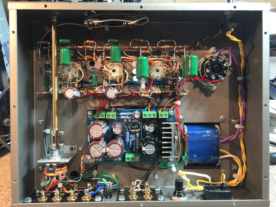
I expect the board to be mounted on a metal plate (maybe 2mm thick steel sheet). This metal plate will be at least 12" long, and the XLR connector, RCA connector and mounting holes for this xo PCB will be near the top. Below this will be the power amp heatsink, on which 2 power amps will be fitted. Below the heatsink will be the IEC mains socket and power switch. Somewhere near the IEC and power switch will be the mounting holes for the soft start module. I'll have to find some separate mounting location for the toroid transformer. So, this metal plate with all this active circuitry will be fitted to the rear baffle of my speaker enclosure. Since my speaker enclosures are much larger than 12", I'll have space above the metal plate on the rear baffle for my passive mid-to-tweeter xo.
BSC: global or just low-pass
The BSC block is supposed to apply to the midbass branch if you're doing a normal 2-way speaker design. It's supposed to span both bass and midrange if you're doing a 3-way where the woofer-to-mid crossover frequency is really low, as in my case. So, though my crossover will be a 2-way design, I'll need the BSC block to be global, so that it spans both branches. However, someone else may want to use my PCB for a conventional 2-way speaker (heck, I myself am tempted for one of the Asawaris maybe), so I'll keep jumpers. You can take the PCB and choose which jumper to add, to keep BSC global or just for the low-freq branch.
I won't provide trimpot-adjustable BSC. I'll provide for a 4-way DIP switch, so that you can select 0/2/4/6dB of compensation. BSC is one attribute which I believe may need adjusting even after a speaker design is finished, because it depends on room placement.
Optional LT
I'll provide an LT block, but you may not want it if you are doing, for instance, a ported design. I love sealed bass. I'll be highly likely to use it. I'll provide jumpers, and you can add the appropriate jumper to bypass the LT or use it. In fact, one of the biggest reasons to go active for my 3-way speakers is because I want to use sealed bass, which often requires LT. I aim for F10 at 20Hz, with a Q of 0.6-0.7.
No notches
Notch filters are common in complex active filters, but I'm not providing for any here, because I'm primarily aiming to use the circuit for woofer-to-midrange xo, at quite low frequencies. For this xo, there will not be the need for any notches in most cases. Those blocks are usually needed at higher frequencies.
No spreadsheet for easy calculations
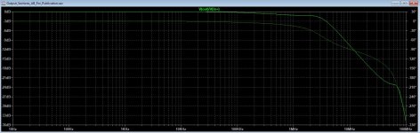
It has been a tradition that active analog xo designs have come with a handy spreadsheet (or even a Windows executable, for Rod Elliot's board) so that you can just say what your Fc is and you get the R and C values for an LR4 xo. My board can be used that way if you want, but I don't intend to use it that way, ever. I expect to design and optimise my xo in an active xo simulation software like VituixCAD (or SoundEasy/LSPCad if you prefer) and
tune the knee frequency and Q to get exactly the phase-aligned
acoustic curves I need, after loading the actual SPL measurements of my actual drivers on my actual front baffle (a lot of actuals there but I'm trying to make a point here). I have no use for textbook electrical filters.
So, if you want to use my circuit boards, you'll need to use my design approach with active crossover simulation software, or you can use one of the spreadsheets from somewhere else.
No trimpots
I don't have trimpots in my passive xo, and the speakers I've made sound lovely. I have no idea why I should need gain control trimpots for my active xo. (Modern crossover simulation software is next only to Hogwards magic, isn't it?) So, I'll provide gain control trimpots in my circuit, but I'll also provide places for a voltage divider with two static resistors, so that you can play with variable gain if you want, but you can later remove the trimpot, measure the two legs, and replace the trimpot with the static resistor pair. Or just keep trimpots in permanently, it's your choice. I'll make provisions for top-adjusting multi-turn Bourns trimpots -- maybe 4-turn and 12-turn options.
Cascade for 3-way?
Two of these boards can be cascaded for a mono 3-way design, I guess. I'll try to provide for a mechanism for supplying the regulated power rails to cascaded boards from a single board, so the PSU circuit can be populated only on one board. That way the tall heatsinks on the TO220 pre-regulator transistors, the 3-pin voltage regulator ICs and the supply filter capacitors can all be on the topmost board and other boards can be stacked below it close by. Of course, if you need anything other than a simple 4th order filter for your xo (my mid-to-tweeter xo often do), then this board won't be of much use for your 3-way or 4-way designs.
Github
The design files will go into a public repo at GitHub. Finally, with GitHub and KiCAD, we have a full open source suite of systems and products which allow us to do open hardware without having to attach zip files to posts in a forum like this. With Git, both CAD files and associated documentation (README.md) will be version controlled with Git tags, so you just check out a specific revision. All files will be published under a Creative Commons open source licence.
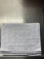
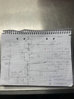
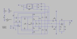
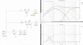
I've attached just a top level block diagram. Each block here is an opamp.
Will need your help
Will look for inputs for all aspects. I'm no expert.
PS: is there any way to keep the first post of a thread permanently editable? If yes, I can keep updating this thread as the project progresses.


