Does anyone know of any graphs which show the measured high-frequency horizontal polar-response of standard, off-the-shelf type, cone drivers when mounted vertically and inverted, so as to radiate omnidirectional from the back-side of its cone? Meaning, like in an Ohm Walsh style driver configuration, except utilizing a normal cone driver instead of a Walsh driver as the radiating element. This has been done before in many diy omni designs, and also, seemingly, in commercial speakers as well. Including, I believe, in Ohm’s current omni speaker range which don’t appear to utilize a Walsh driver. Instead, utilizing, what appears to be a normal cone driver, presumably, to dramatically lower speaker cost.
I’m particularly interested to know whether the horizontal polar-pattern at the highest frequencies of a cone driver are, indeed, radiated 360 degrees from the back-side of a vertically and inverted mounted driver, as seems the presumption. I read one of Ohm Acoustic’s omnidirectional driver patents, which indicates that, what appears to be, a normal cone driver radiates 360 degrees horizontally from the back of its cone up to at least 8kHz, where it is then crossed to a tweeter in the patent. The driver in the Ohm patent is not depicted as, nor specified as a Walsh type driver. A Walsh driver clearly looks different in design than that shown in the patent drawings, and also is easy to picture as naturally radiating 360 degrees over its full frequency range.
I’m particularly interested to know whether the horizontal polar-pattern at the highest frequencies of a cone driver are, indeed, radiated 360 degrees from the back-side of a vertically and inverted mounted driver, as seems the presumption. I read one of Ohm Acoustic’s omnidirectional driver patents, which indicates that, what appears to be, a normal cone driver radiates 360 degrees horizontally from the back of its cone up to at least 8kHz, where it is then crossed to a tweeter in the patent. The driver in the Ohm patent is not depicted as, nor specified as a Walsh type driver. A Walsh driver clearly looks different in design than that shown in the patent drawings, and also is easy to picture as naturally radiating 360 degrees over its full frequency range.

I don't have measurements on a driver for exactly this configuration, however, I have some related experience.
My particular DIY interest lies with dipole loudspeakers. To that end I have sought out drivers that have symmetrical radiation to the front and rear when the driver is suspended "nude" e.g. by wires in free space. When I was searching for candidates for a midrange type driver used in this way I measured many drivers from 5" to 8" or 10" from the front, and then the rear, for a variety of angles in a horizontal plane centered on the driver. The rear measurement data is similar to what you are asking about for a driver mounted facing down on to a closed box. What I found was that above 1k-2k Hz the basket and magnet started to make the rear radiation pattern much different than the front. This happened more with small drivers where the magnet is almost as wide as the cone and the basket was small and not open. The rear-side pattern breakdown means that most cone type drivers are not going to be very useful above a few kHz, and whatever response you do get will be a mess. If you think about it, to the front the pattern is narrowing, meaning that off-axis responses are falling off due to interference between sound emanating from different points on the surface of the cone. Only the central on-axis position remains (mostly) unaffected by the interference. But to the rear, the magnet and basket are in the way of the on-axis position, and that would be pointing up to the ceiling anyway. It is the angles greater than 60 degrees that will be "towards" the listening space.
If you recall, the Ohm Walsh driver had a very long/deep cone profile and this kept the sides open and the magnet assembly far away from most of the cone. That will provide much better HF output in the "sidways" direction compared to your normal cone driver, which is not very deep and the side of the cone not very exposed.
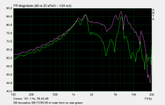
For example, here is a plot of the front and rear ON-AXIS responses for the SB Acoustics SB17CRC35-4 driver. The rear response is in green. The magnet structure decreases the rear output by being directly in the way. This is really not all that bad in terms of pattern differences, just the SPL is very different. Off axis things tend not to get better because the driver is not really designed to radiate in that way.
My particular DIY interest lies with dipole loudspeakers. To that end I have sought out drivers that have symmetrical radiation to the front and rear when the driver is suspended "nude" e.g. by wires in free space. When I was searching for candidates for a midrange type driver used in this way I measured many drivers from 5" to 8" or 10" from the front, and then the rear, for a variety of angles in a horizontal plane centered on the driver. The rear measurement data is similar to what you are asking about for a driver mounted facing down on to a closed box. What I found was that above 1k-2k Hz the basket and magnet started to make the rear radiation pattern much different than the front. This happened more with small drivers where the magnet is almost as wide as the cone and the basket was small and not open. The rear-side pattern breakdown means that most cone type drivers are not going to be very useful above a few kHz, and whatever response you do get will be a mess. If you think about it, to the front the pattern is narrowing, meaning that off-axis responses are falling off due to interference between sound emanating from different points on the surface of the cone. Only the central on-axis position remains (mostly) unaffected by the interference. But to the rear, the magnet and basket are in the way of the on-axis position, and that would be pointing up to the ceiling anyway. It is the angles greater than 60 degrees that will be "towards" the listening space.
If you recall, the Ohm Walsh driver had a very long/deep cone profile and this kept the sides open and the magnet assembly far away from most of the cone. That will provide much better HF output in the "sidways" direction compared to your normal cone driver, which is not very deep and the side of the cone not very exposed.
For example, here is a plot of the front and rear ON-AXIS responses for the SB Acoustics SB17CRC35-4 driver. The rear response is in green. The magnet structure decreases the rear output by being directly in the way. This is really not all that bad in terms of pattern differences, just the SPL is very different. Off axis things tend not to get better because the driver is not really designed to radiate in that way.
Attachments
If you want an omni pattern, just mount a very small diameter driver, facing up, on the top of a cabinet. The small diameter cone can radiate to the sides to a relatively high frequency. For example, the Linkwitz LX-Mini uses this principle and so did the Pluto.
While for a dipole configuration, this information is still very helpful. Especially, this; “What I found was that above 1k-2k Hz the basket and magnet started to make the rear radiation pattern much different than the front. This happened more with small drivers where the magnet is almost as wide as the cone and the basket was small and not open. The rear-side pattern breakdown means that most cone type drivers are not going to be very useful above a few kHz, and whatever response you do get will be a mess.”, and also your plot which shows an, essentially, unaltered frequency response to at least 1 kHz. All, very helpful information.
Thanks, Charlie.
Thanks, Charlie.
My concern over Linkwitz’s Pluto design is that it forces the use of a mid-tweet driver in order to reach down far enough to meet the mid-bass unit at a frequency were it still is omnidirectional. Which, (coincidentally?) is @ 1KHz for the Pluto design, if IRCC. I had my eye on a particular Seas 220mm mid-bass unit, and was hoping that the back-side radiation from that driver might emit over 360 degrees up to a frequency high enough to enable a crossover to a 20mm dome tweeter. Meaning, around 4KHz. You data shows me that I need to re-think that.
One problem this sort of design approach will encounter is that the direction that is "towards the listener" is far away from the usual "on axis" direction, e.g. it is between 60 and 90 degrees off axis. These angles are the first ones that are affected by beaming or pattern narrowing. One way to ameliorate this to some degree would be to place the upfiring driver at or near the floor. That way the listener is at more of a 45 degree angle to the source and you can use a driver of a particular diameter to a higher frequency. I think SL was interested in positioning the driver so that the listener was at 90 degrees to it when it was facing up because there is no baffle step for this angular position.
The chassis of the driver will have a big effect, especially with larger cones. With 30 mm diameter I'd guess the dispersion is very good, around 165 mm with a cheap pressed steel chassis, perhaps not so good. I'd recommend a woven glass-fibre cone. I'm hoping to experiment a bit more in this area, buy only using ears, rather than any meassuments.
A driver with a small magnet and cast basket with narrow spokes would be better suited but also be a strange, rare beast. Even if one could be found, dispersion would be limited to midrange along the horizontal axis dictating the need for a tweeter. Old school is to use a reflector with a normally configured driver. My own experiments along these lines lead me to conclude that vertical dispersion is just as desirable in an omni, at least for a stage height that matches the width and depth.
Attachments
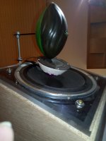
Creative use of a Nerf football as a reflector for the midrange driver. How effective do you find it? What’s that you are using for the midrange enclosure/woofer reflector? Also, please share with the thread your assessment of the subjective result.
I tried a few different reflectors for the tweeter, from a 2" hockey practice ball to 6" styrofoam hemispheres. The woofer midrange reflector is scavenged from a children's snowball maker, with hard setting modelling clay to smooth the curvature to the tweeter flange. The acrylic baffle along with the drivers and diffusers form a modular unit that can be installed on different enclosures for experimentation. The woofer is connected full range to a Pass ACA with a single cap for the tweeter. The arrangement sounds better than it looks at this point, needing only cosmetic enhancements IMO.
Subjectively, i spent most of my audiophile life listening to large planar dipoles driven by high power amplifiers. These are my explorations into a smaller, simpler system while trying to maintain a similar level of lucid transparency. I haven't been entirely successful with bass integration as yet but the system as is is very involving, particularly with classical music that benefits from a large, spacious sound stage. Listening to planars for most of my life has left me with a heightened sensitivity to driver alignment and these are quite good in that regard , even off axis, with misalignment only becoming obvious when standing close above the speakers. Even then it's not bad as the physical distance between the drivers is still closer than the usual flat baffle arrangement. With only a single cap for a crossover the electrical phase is pretty good, too.
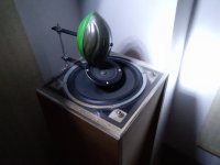
I don't like box speakers but these installed in TL enclosures (2nd photo) didn't sound like box speakers to me. Bass was lumpy but the woofers were not suited for TL cabinets. The search for good bass integration continues but the midrange is fine enough for this old guy used to listening to ribbons. 🙂
Subjectively, i spent most of my audiophile life listening to large planar dipoles driven by high power amplifiers. These are my explorations into a smaller, simpler system while trying to maintain a similar level of lucid transparency. I haven't been entirely successful with bass integration as yet but the system as is is very involving, particularly with classical music that benefits from a large, spacious sound stage. Listening to planars for most of my life has left me with a heightened sensitivity to driver alignment and these are quite good in that regard , even off axis, with misalignment only becoming obvious when standing close above the speakers. Even then it's not bad as the physical distance between the drivers is still closer than the usual flat baffle arrangement. With only a single cap for a crossover the electrical phase is pretty good, too.
I don't like box speakers but these installed in TL enclosures (2nd photo) didn't sound like box speakers to me. Bass was lumpy but the woofers were not suited for TL cabinets. The search for good bass integration continues but the midrange is fine enough for this old guy used to listening to ribbons. 🙂
Hi I'm curious as well let's say mounting it inverted what the highest it can be crossover let's say for a 6.5in , 8in, and a 10in, to keep it playing low up to 300hz,500hz or 1000 hz would it still play Omni directional up to these frequencies or what is the max for all three the 6.5in, 8in, and 10in got all three and what to build something but need advice
I always thought this would be a good inverted candidate. Minimal frame and magnet compared to cone.
https://www.rocktheboatmarinestereo...lQwtEGUe6v90RttW7QYLA18xE0RjhDNBoCaC4QAvD_BwE
https://www.rocktheboatmarinestereo...lQwtEGUe6v90RttW7QYLA18xE0RjhDNBoCaC4QAvD_BwE
I can try & get a measurement off the back side of our N7 & post it. Most of our measurements are near field & open baffel, so this will be different.
That does look like a very good canditate, but it's a lot of money to spend when you don't know what it will sound like used as an inverted Omni, some drivers sound dreadful used like this.I always thought this would be a good inverted candidate. Minimal frame and magnet compared to cone.
https://www.rocktheboatmarinestereo...lQwtEGUe6v90RttW7QYLA18xE0RjhDNBoCaC4QAvD_BwE
What are the T/S parameters?I always thought this would be a good inverted candidate. Minimal frame and magnet compared to cone.
https://www.rocktheboatmarinestereo...lQwtEGUe6v90RttW7QYLA18xE0RjhDNBoCaC4QAvD_BwE
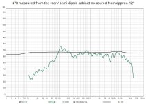
Yes, please do. To be clear, the desired measurement is not simply off the rear of the driver cone, but at 90 degrees to the cone’s driven axis. Thanks.I can try & get a measurement off the back side of our N7 & post it. Most of our measurements are near field & open baffel, so this will be different.
Interesting drivers. On a quick review of your website, I did notice that both the Reference 7 and 9.5 appear to feature identical T/S parameters. Some kind of unintended duplication I presume.
Last edited:
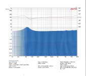
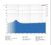
Yep - I will measure based on how the driver would be listened to....90 degrees with driver facing down. I have attached the T/S for the N7 & N9.5. The website needs updating. A never ending battle.🙄. I have a driver I can use, but my cabinets are on loan to a friend, so will see what I can do soon.
Attachments
- Home
- Loudspeakers
- Planars & Exotics
- Inverted mounted driver polar-response