Help diagnosing Rockford Fosgate 500S early clipping

I'm in the process of repairing a 500S, circa 2002, pcb# PC-3082-D (I have the schematics). The initial problem was a blown output FET on the left channel, sending negative rail voltage to the output terminal. I replaced all 6 FETs on the left channel and reset the bias. That channel works well now, with the output going to within 1-2v of rail before clipping with a 4 ohm load.

While testing the other (right) channel, I found another issue. I either missed this during initial diagnosis, or something got damaged during the repair. The output, with or without a load, clips well before reaching rail voltage. The clipping is equal on both the positive and negative side of the signal. Another symptom is that it appears the overall gain of the right channel is less than that of the left channel (for equal input signals). It's almost as if that channel has no gain, and the signal at the output terminal is merely the input signal fed via the feedback resistor (R244).

Tracing the signal through the design, and comparing the bad (right) channel to the good (left), I find the following differences:

- good signal at the + side of C223 (matches the signal at C111)
- bad signal at the base of Q203
- bad signal at the collector of Q201

I used my multimeter's diode test function to test Q201, Q202, and Q203. All appeared fine. I also tested all of the resistors in that part of the circuit, and again all was fine. All of the output FETs test fine too. The +/-14v supplies are also good on the right channel (as tested at R215 and R219).

My initial thought was that Q201 wasn't turning on properly, so I tried shorting the collector to emitter. That didn't help, and made the output look worse.

Aside from starting to randomly replace components, where else should I look?

Thanks!

  • Locked
The Biology and Immunology Corner

As requested by unpopular demand, a lounge talk dedicated to biology Q&A and discussion.

I unintentionally contributed to the hijacking of the, still very relevant, supply chain thread in regards to SARS-CoV-2. So here is a thread specifically for the discussion of biology, immunology, virology, and general science as it relates to the current outbreak and larger issues.

Feel free to ask questions (I'll do my best to accurately answer), provide your own thoughts, complain about response, or argue against panic and media coverage. It's all good! That said, I do reserve the right to call you out for misinformation or science rejection in as respectful a manner as possible.

Bob Cordell's Amplifier designing for beginners

Hi guys. I'm a newbie and I'm looking for some good literature to get started. I found Bob's book and I was wondering if the first part of his book is enough to get me started with some basic amplifier designing. Is there any other literature or tutorials you can recommend me?
By the way, I have some basic (to intermediate) understanding of electronics components and circuits.

Home LP system

Hello!


Let me introduce my home vinyl system, the heart of which are original transistor phono stage and power amplifier of my own elaboration and assembling. Also Canton Ergo 690 DC acoustic systems and old Soviet LP player Электроника ЭП 017с are used. About a month ago I bought a new source - MoFi electronics STUDIODeck+ and maid some records with it.
You can estimate the sound of the system on YouTube:
YouTube


Of course, You Tube records are not the perfect instrument for sound quality evaluation, nevertheless any your opinions would be interesting.

Making Spice Models for tubes

Hi All,

I needed a spice model for EL86 tube (triode mode). there are several models on the web but all of them use the simulation method based on some kind of formula. I wanted the model which is derived directly from the datasheet. Since I could not find one, I made it. I use LTSpiceIV and the model might be the program specific, but the methodology is very general and can be used for creating spice models for any triode and simulation programs.
I will describe the process of creating the model step by step.


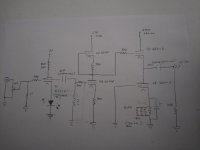
1. The model is shown in the attached file. In nutshell, the triode is modeled as a voltage controlled current source. The output current is evaluated based on Vgk, Vpk and triode plate characteristics. Plate characteristics are loaded in the model as the points and the spice program does the interpolation. None of the tube constants (u, gm or Rp) are used. The model is simple and can be easily modified for other tubes.
Here are the essential elements of the model with comments and explanations:

a) Connections are Plate (P), Grid (G) and Cathode (K).

b) Dummy voltage source E1 is used to generate the voltage equivalent of V(p,k). E1 is used as an input voltage for the current sources (see below).
E1 n001 0 value {V(P,K)}

c) Dummy voltage dependent current sources (G0 - G12) are used to generate currents representing each I(Vgk=constant) plate curve. There are as many current sources as the curves in the tube plate characteristics. In the EL86 datasheet there are 13 curves (Vgk=0, Vgk=-2.5 .... Vgk=-30). The data comes directly from the plate curves. The curves are the plate current I(mA) vs plate to cathode voltage Va(V) at different grid voltages Vgk (V). The input voltage for each GX current source is E1
Here is the example of the current source for vgk=-5V:
G2 n102 0 n001 0 table (0 0
+ 38.652482 0.000709
+ 41.331757 0.001694
+ 44.011032 0.002561
......
+ 168.794326 0.200355 )

d) Current dependent current source GPK is used to generate output plate current. Current source interpolates current based on the lookup table.
GPK P K value={Table (V(g,k),-40,0,-30,I(G12),-27.5,I(G11),-25,I(G10),-22.5,I(G9),-20,I(G8),-17.5,I(G7),-15,I(G6),-12.5,I(G5),-10,I(G4),
+-7.5,I(G3),-5,I(G2),-2.5,I(G1),0,I(G0))}

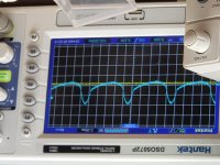
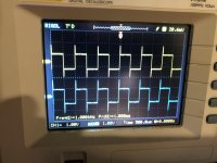
e) I(Vp, Vgk=0) curve is used for all positive Vgk voltages. This assumption is not true for the real triode. However, it is quite useful for simulation of the receiving type tubes which should be operated with Vgk<0. In the simulation, plate current saturates when Vgk>0 and waveform is intentionally distorted. You can remove or modify this condition easily to alter tube behavior in the positive Vgk region.

f) Cutoff grid voltage is defined somewhat arbitrarily as an interpolation of the Ip(Vpk) points to Ip=0 at maximum Vpk (in this case Vpk=300V). For EL86 this happens approximately at Vgk=-40V.

Now what's left is to fill the model with the data derived from the plate curves.

2. I obtained the electronic image of the plate curves from the datasheet. My digitizer program (see below) takes jpg, tif and png but does not take pdf files as an input. So, there is an extra step of converting pdf to jpg file.

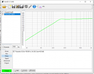
3. I used GetData graph digitizer from here Digitize graphs and plots - GetData Graph Digitizer - graph digitizing software. You can use any other program, but I like GetData for its simplicity. I imported jpg file to the program and semi-manually digitized all curves. It took me about an hour to get everything right. Digitizer outputs the data in several tabulated formats. I used Excel format for data output file.

4. The last step was to open file in Excel and copy-paste the appropriate data columns in my model text file. To edit the model file I used LTSpiceIV text editor, but notepad works as well.

Comments and ideas are welcome 🙂

Attachments

Bookshelf Upgrade Conundrums

I have a set of Polk S20 bookshelf speakers that sounded pretty good with my system. Long story short, they were damaged recently and the drivers are trashed. I've looked at OEM replacements but I am put off by the cost ($65 ea for the woofer, $80 ea for the tweeter).

So my line of thinking is replacing them with a set of drivers that very closely matches the Polk specs. Parts Express has a huge selection and I'm thinking a 6.5" and tweeter from Tang Band might be a good fit for the Polk cabinet and crossover.

When I say specs I'm looking mostly at sensitivity, recommended cabinet size, frequency response and crossover point.

What do you guys think? Does anyone have a recommendation for better replacements? Am I wasting my money and should I just buy those Elac reference speakers I've been drooling over for the last 6 months, lol!

Thanks in advance for your feedback and helpful criticism.

6S41S WCF OTL Headphone Amp

I am trying to design an OTL that will drive ANY impedance cans. My main phones are Audeze LCD-2 CB which are 70 ohms. I also have 32 ohm ohm HE-4xx and 300 ohm HD-650s. I have built four HP amps using Aikido topology, which sound fantastic with 300-600 ohm HP, but not enough oomph for low impedance. I do have 600 ohm OPT but the secondary is only 8 ohms (I was saving them for a 6C33C project). The schematic is attached (preliminary), PS schematic to follow.

Attachments

  • IMG_20200306_133617024.jpg
    IMG_20200306_133617024.jpg
    375 KB · Views: 657

WTB: TIP-140 TIP-141 or TIP-142 Transistor in TO-247 Package

Hi folks, once again I need a lone part to complete a repair..

A TIP-140 / 141 or 142 transistor in the TO-247 (larger style) package. If you also happen to have a cosmetically-matching TIP-145 / 146 or 147 that would be dandy. Want to restore the +/-18V regulators on this computer back to factory appearance.

YES! I KNOW THERE ARE MANY COMMERCIAL SOURCES 🙂

Thank you..

Heat sink for 21st Century Maida Regulator

Not exactly tube related but I intend to use this regulator for a tube preamp. When I use the supplied calculator and input 330 v as the desired output (I think the input will be around 350), the spreadsheet says Output voltage adjustment range is 475 high to 375 low. First question, how can that be if I specified 330v output? Second question, heat sink for Q1 say thermal resistance of 5.32. Since I'm a tube guy, not a SS guy, can anyone direct me to an appropriate part number (Mouser or DigiKey)?
  • Like
Reactions: nerdorama

Simulating 18sound 10nmba520 dogbox

The purpose is to simulate different dogbox designs for the 18-sound 10nmba520. This is the driver chosen by Troels Gravesen for The Loudspeaker, The-Loudspeaker

First I use Winisd to figure out a critically damped box size, and its potential maximum sound pressure.

Box size is 11,39 liters. Filter parameters are shown in diagram. System power is 130 W, cone excursion is xmax at 150 Hz.

Attachments

  • 10nmba510.png
    10nmba510.png
    47.9 KB · Views: 261

Low output from Eden WT800 in Bridge Mode

Hello all.
Okay, I've been lucky with trial, and error troubleshooting, and eventually repairing circuits. Don't want to waste anyone's time here with stuff I should already know. But I just can't figure this one out.
Getting weirdness from WT800 in bridge mode.
First ting I did was replace the open 27K feedback resistor that had failed open.
In bridge mode, I'm getting a larger signal on negative side (inverted right channel) than I'm getting from the positive side (non-inverted left channel).
Both right, and left channels are putting out the correct wattage in stereo mode.
Bridge switch seems fine. The R channel input is being muted by JFETS when in bridge mode. Getting signal from L channel output at 12K/27K junction.
When scoping output negative terminal I'm getting 36V RMS before clipping
Positive terminal is reading 22V rms.
At this point, I can apply more signal and get 36V on Pos teminal as well, but the negative side is clipping.
With the above 36/22V RMS scenario, I'm reading 58V across NEG and Positive with DVM.
Obviously, far below the specified 800 watts for bridged into 8 ohm load.
Using electric stove hotplates paralleled to get a perfect 8 ohms.
Hoping someone can see something obvious here.
I appreciate, and humbly await any response to guide me.
Thanks,
Stan

http://schems.com/bmampscom/eden/Eden WT500, WT600, WT800 - Schematic.pdf

hammond power transformers fluctuating

Hi, I have two hammond 373bx power transformers. I've used hammond transformers a lot and they always work great. But now these two, both!, i wired them up to my variac, blue and white on the variac and brown and black wrapped together and .... nothing. Both won't do anything. No high voltage, no 6.3 and no 5 volt. If I bump the voltage to about 100 volts on the variac, the high voltage starts to swing between 0 and 50 volts. I don't get it. Thist is not my first time. What the heck am I missing? :/

Here is the wiring diagram:
An externally hosted image should be here but it was not working when we last tested it.

HDMI related hum

Dear All,

I have an issue that leaves me puzzled. I have a totally DIY system, amps, pre, etc. The system is completely silent. One of the source is my Home theater amp for the front channel. When I attach the amp, the system is still completely silent.
I have a very strong hum when I attach the TV to the amp via HDMI. Note that the TV is NOT the source of audio, but it is used only as a monitor. Both TV and Home Theater amp (Denon 3808) do not have grounding.
An even more nastly noise I get if I connect the Macbook as a source via HDMI. in this case I can hear the hard drive moving.

Any solutions ? I could not find any HDMI galvanic isolator in the market.

Thanks for help.

D.

Audio Amplifier Module grounding help

Hi I am relatively new to electronics so please take it easy on me.

I am building a DIY Bluetooth Speaker, everything works fine when I use my breadboard amplifier that I build using LM386. But I need a stereo output to decided to use the PAM8043 Amplifier IC. To save time I directly purchased the PAM8043 Amplifier Module from the link.

As you can see in the image (from the link) the module is powered by +5V and ground and the audio input L,R and Ground. Should I connect the audio ground with the power supply ground? My logical brain says it should not be done, but when I don't do it I get a humming noise and when I connect both grounds it the PAM8043 is getting hot. So what could be the problem here?

Crossover build

I am working on my first crossover network from scratch, probably a 2nd order 2-way. My questions are twofold:

1) Is there any difference in performance if I build them with point to point on a perf board vs using a stock foil board with the large pads/grounds?

2) Most of the stock foil boards are only for the basic 4 components plus maybe a fuse. What do you guys do for L pad resistors, Zobel, BSC etc? Is everything on the same board or is there a second board?

Thanks,

George

Interesting new whizzer speaker if you're into single drivers

There's a company that makes one of the leading guitar amp\simulators out there, called Kemper. They just released a custom 12" whizzer driver called the Kone that is meant to use their proprietary DSP in the amp to coax near full range response from the driver. I have one for use with their system, and using the DSP and external audio with it set in full range, was frankly shocked at how good it sounded with high quality audio. Far better extension and less tubby mids than a stock Eminence 12LTA.


The driver design is described as having a modified whizzer that allows higher frequency response, but it appears the overall response of the driver is not usable without their DSP correction. It would be interesting to throw a RTA on one of these and see how it does full range. Also it is only available in 4 ohms.


The site shows the Kab (a standard 12" cab with a Kone installed), but you can purchase the Kone driver on its own. It's made by Celestion in China, and is very high quality with a beautiful look.


KEMPER Kabinet & KEMPER Kone | Kemper Amps

Cec Amp71

Hello,

I have just read some piece of information I found interesting. It is taken from http://www.rcm.com.pl/cec/cec_main.htm , and it concerns CEC's new integrated amp, AMP71. The original text is in Polish, here is my (poor 🙁) translation. I may have messed it a bit, I believe HPotter would do a better job. Anyway, here it is:

AMP71 works in Class-A, giving 200wpc max, without generating huge amount of heat. Enough to say, that heatsink temperature of a working amplifiers does not exceed 40 deg. C. What's more interesting, all A class amps, with power exceeding humble 30wpc, have large cases with enormous power supplies. AMP71 has traditional ps with 160000uF caps and two highest 🙂)) quality toroid transformers (650W each). Using two toroid is caused by fully symmetric design, including speaker terminals, not connected to the ground. Basic idea is very simple from theoretical point of view, yet its implementation is not that simple. To make long story short, signal is amplified by single bi-polar transistor, working in pure class A. It amplifies signal from input, which basically means that AMP71 does not contain pre-amp section, and the whole amplification is done by single gain stage without feedback. (...) The most interesting part is how to gain 200W in class A using only one gain stage. As we were said by designer, Mr. Carlos Candeias, gain is set between 40 and 50, and with given 100mV input sensitivity results in 5V max on the output. So where is that 200W coming from? The gain transistor is supported by current source made of 8 transistors per channel, that can easily generate 200W while working in A class (its very high impedance does not influences the signal). Roughly speaking, the power transistor works as switch controlling the
current transistors. The whole process is controlled by detecting output signal and informing the current source about changes, that are apropriately amplified. (...)

Does it sound familiar? Any comments, guys?

Regards,

Marcin.

How to build a Gain module for Subwoofer Amp without hum problem (TDA8950)

hi members ...

i need to build a gain module to compensate for the input sensitivity of my TDA8950 (dont know why it has low input sensitivity). But now the problem is after the low pass filter the signal will pass into an inverting op-amp section which has gain of around 8db and this has given me Hum problem when the subwoofer volume potentiometer is turned more than 60%.

Low pass filter is 2nd order LR and there is an inverting summing opamp stage that combine the Left and Right channels and this stage has unity(1) gain ... only the final stage operates with gain while inverting back the signal phase

thanks

MA CHBW70 sims - vent air speed

I got a couple pairs of drivers from Scott recently, including a pair of CHBW70.
I put the data into WinISD to the best my knowledge allows. I got the red warning about dodgy parameters.

The model seems to work. The curve looks as one would expect soi believe the parameters are ok. Surprising LF extension in small enclosures the only 'alarm' that rang for me. But hopefully this is correct as Scott did mention they would go down into the 50s.

The biggest issue I see is the vent air speed. Even with a 1w signal, the curve just shoots up off the graph intimidating huge air speeds. Maybe this is a function of the parameter input being bad?

Best regards
Jim

Small 12-19V 15-25W power supply (similar at Neurochrome smps-86)?

Looking for a 12-19V DC output power supply, rated 15-25watts, for powering a low powered ITX motherboard.

Neurochrome SMPS-86, fitted with Meanwell 12V power modules seems attractive.

Any other better options for me, with similar dimentions.

I'm trying to do an internal power supply as opposed to an external linear power supply in a small enclosure.

Thanks

FCAM123 line source for compact outdoor 12V application

Hi! I'm thinking of experimenting a bit with line sources for outside use.I read from martinsson that the FCAM123 sounds good outdoors and it looks like a quick build so I already ordered 12 faital Pro 3FE25-16s. Only 12 because my plan is to divide the line array into two smaller, 6-units long arrays that one can attach together to form again the 12 unit array. This way, one can make a mono stack for electronic music (my plan is to use a THAM12 as subwoofer) or have stereo set-up for other applications or locations.

I have been reading about how line arrays behaviour can be improved by means of delays, shading and progressive crossover settings. I'm considering using an NL4 conenctor for each half so I can apply different settings to the lower 4 and the 2 upper faitals with the aid of a minidsp 2x4. This way, when both are attached I'd have 4 zones with 4-2-2-4 speakers each.

Do you have any experiences with such set-ups? Any stuff I should take into consideration?

Thanks!

Hafler 1977-80s Paint

I'm restoring some David Hafler amplifiers and found a paint match , I think.
The DH paint looks like from 1972-3 GM auto paints. A very dark metalic olive. The Duplicolor 'DE 1651 Cast Coat Iron' shown in pic is very close. We'll see how well it matches the front panels/knobs. Its a high temp ceramic paint.

Attachments

  • 2E27C3C2-A97F-43CA-812A-F101F4FAC567.jpg
    2E27C3C2-A97F-43CA-812A-F101F4FAC567.jpg
    525.3 KB · Views: 375
  • 3D495AA2-4B9C-4415-81D1-7B7C8DA33C99.jpg
    3D495AA2-4B9C-4415-81D1-7B7C8DA33C99.jpg
    731.5 KB · Views: 373

DSC1- V2.6

I have this DSC1 V2.6 for sale, it is new, with tantalum resistors and transformers LL1684. For personal reasons, I won't have time to finish it.
It cost me 542 euros with transport.
I can break away from it with 300 euro + transport + 4% paypal.
Thank you.

Attachments

  • 20200322_103311_resized.jpg
    20200322_103311_resized.jpg
    361.9 KB · Views: 291

Anyone Know what LED this is Krell S1200

I was working on Krell S1200 output section and inadvertedly damaged the LED diode on the board. They are diagnostic diodes for use internally at Krell I think. I replaced it with a slightly different one from a car stereo . The original has 1.6v drop and car stereo one has 1.75. I had replaced bank of transistors due to hissing caused by high DC offset going into the output signal cap but still getting .15v dc offset which is the difference of the diodes (was previously getting well over a volt before replacing transistors).. With alot of modern diodes being sold for light output for lighting it seems like it may be tricky getting the right one. Tried contacting Krell but got corona virus message and they are not there according to message. Anyone know what these might be?

Attachments

  • IMG_6893.jpg
    IMG_6893.jpg
    992.1 KB · Views: 86

Plans for L Cao F6

What enclosures would people recommend for the L Cao F6? I see a few other people have used them in Karlsonators, what other options are there please? I believe the FHXL would be "OK", but not great, any other ideas please? I've not found any enclosure plans specifically for this driver. Specs are here:

L.Cao LAOCAO F6 6? 12W Full Range High Sensitive Speaker W/ Paper Cone

Building a cheap 250W dummy load

Hey dudes.

I was planning on making a cheapo dummy load like following:

Two 3.9 ohm 50W wire wound resistors in series, installed on a large heat sink taken from a scrapped 100W mono amplifier.

This would make a nice 8 ohm 100 W dummy load, I think.

I'm planning to make two sets, and connect them in parallel, for a 200W 4 ohm dummy load.

But here's the kicker... I need 250 W. So I was thinking of submerging the bottom halves of the heatsinks in water. No risk of shorts or anything like that.

What do you think? Could it work?

Two Jeff Rowland 12's from one SPS ??

Long story short, I have semi-inherited a Jeff Rowland Model 12 amp.

BACKGROUND IF YOU CARE :

This "one" Model 12 unit is actually four separate boxes: two switch mode power supplies and two amps. The power supplies are connected to the amps by weapons-grade umbilicals.

One power supply is dead dead dead, and has been dead for years. Many, many attempts to have it repaired have failed, and heck I've been trying since last November just to get someone to return my calls. Forget Jeff Rowland or any "authorized repair centeers", I think they're hiding behind the door when you try to reach them.

Rowland does not publish schematics, or offer any assistance whatsoever.

What I've eventually learned is nobody messes with these JR switch mode power supplies, even Rowland in the past has "rebuilt" them as linears, so you sent your dead smps in for repairs, he charged a fortune and you got a linear back in that same chassis.

THE REAL QUESTION :

Can I drive both amps from the surviving SMPS?

I haven't delved into JR's SMPS design too deeply (not as if you really can), but it seems plausible.

I'm in a standard size family room (12x18 maybe) type space with pretty efficient speakers (>95dB) and just don't crank Led Zep like I used to.

This would require spending a good bit of time sourcing the connectors and building a proper split umbilical. Mocking one up properly looks like it would take almost as long as shipping the connectors, so might as well just do it right the first time.

RELATED THOUGHTS :

Dead JR equipment, since it can't be fixed, has an approximate market value of $zero, give or take shipping. The boxes are cool CNC machined aluminum, kind of like Lego the way they go together to make different JR equipment. But these are the stubbiest of the JR boxes, so you cant jam much in there if you're repurposing them.

I would hate to immediately fry the good SMPS, because we've been using it to troubleshoot the dead SMPS.

On the other hand, I'm functionally dead in the water unless I really get into mono.

The other down-the-road thought is, ditch the dead SMPS and build a nice linear PS into that box and use IT to drive both amps. I'd already have the umbilical!

But seriously .... thoughts on the original idea of driving both amp modules from the one SMPS?

Thank you.

Inverting Transformers Tubelab SSE

I am planning on my first tube amp build, I have decided on a Tubelab SSE and the chassis design I am working on has the power and audio transformers inverted (upside down). They would be separated from the tubes/other electrics by sheet metal.

I know tube amps, especially SE are very picky about the transformer location/orientation. Can anyone tell me the implications of inverting the transformers?

When is a 200W Power Resistor the Size of a 100W Power Resistor?

A decade ago, I bought some 200W power resistors. Aluminum extruded, 165mm long, rather heavy, to build a dummy load with.

This month, I bought four more of what appeared in the listing to be the same thing (even their chart showing different wattages and sizes showed the 200W being 165mm long). What I received however was only 100mm long. According to the chart, these are 100W units. But they are marked exactly with the same part numbers as my 10 year old resistors.

Either the laws of physics have changed in 10 years (doubtful), or somebody made an error in labeling.

The seller investigated and this morning informed me that this is correct. I don't believe them. The parts I received don't even match specs with their own resistor chart.

I'm reluctant to build the dummy load with these resistors, but if I try to buy them again, I'll probably get the same thing all over again.

So what do ya'll think? Labeling error, or improved physical materials?

Peerless HDS Tweeter too harsh, (Nomex 164)

Ok...I have posted this issue in a couple places...here's what I have figured out so far. My ears are sensitive...my Old ACI's Sapphire III's (Audio Concept Inc) were DVC and when one VC wasn't working because of a bad resistor, I could here it. (The difference in the volume.) I'm sure probably most here, could too!

My build is the Troels Nomex 164's I increased the R1051 from 1.1 ohm to 3.3 ohm. Still at loud levels it hurts my ears after a time. (CD's not so much.) Also, I listen from my Ipod regularly...so I know that is a consideration.

I am running 2 (or 3 depending on what I play) Adcom 2535 amps, with a B&K Ref 30 Pre-pro) with 200 watts going to my stereo pair!

I really want to build the Elsinores...but until a couple days ago thought these HDS tweeters were too "bright". Now I am sure it has to be the xover.


I used Audyn Plus caps, so I am going to try the Silver Janztens on the tweeter section. (The price difference is $8 each I think, compared to the Supremes)


Also I had issues with the solder strips Troels recommended, but I tested the ohm load on my speaks and they are right at 4.5 ohm so I don't think thats the problem!

I really like the way these HDS tweeters sound...so any help would be appreciated!


PLEASE READ THIS.....I have never listen to and enjoyed music at low to moderate levels like these speaker produce! (I have an 18 month old so I have no choice..😉 ) In any case I cannot believe how good these sound at low and moderate, or even mid high volumes. It's just when I really crank up the 200 watts that they start to fatigue. The ACI's didn't have this issue!

Therefore I am convinced it's the Cap...keep in mind the harshness is subtle!


Thanks in advance for any input...and thanks for these forums...freaking AWESOME!!!!!

Electric wiring Thorens 165, multi-meter use during reparation.

Accidentally I damaged a Thorens 165 record player. During repair of that part of the tone-arm I accidentally cut the wiring, so I had to rewire.

Also I wanted to swap the positon of the RCA-outlet of the backside so the channels would be in the same position of the amp. Now I had to desolder those RCA-plugs and resolder after swapping them from left to right, the red plug on the leftside (right audio channel), the black on the rightside (left audio channel, plug outlet on the rightside, as on my amp).
Now I am not a pro and I am learning to solder now but I want to controll the work before I can go further.
I don't want to do a lot to find out later that I made a mistake earlier on.

So I soldered these RCA-plugs after swapping their position in the wooden holes at the back. And now I want to be sure that this connection works with a Mulit-meter. One RCA plug ( I think the red one) gave a reading of 20 or more volts, the other hardly...again I am a rookie at this stuff, I want to learn. So is it normal or do I have to resolder the other plug? If I am doin' it wrong...please tell me cause this is all new for me.

I just want to be able to do this repair because of restoring a good recordplayer but also to be able to do this myself properly. So how do I use the multi-meter to check if my repair worked out? And what would be a proper volt-reading of RCA-connection from the wire-chassis to the RCA outlets on the back?

(The RCA-outlets are by the way not original, originally Thorens had a RCA-wire (grey) that went from the
bottom-plate to the amplifiere. The RCA-plugs here are a modification of later times '80ies/'90ies or later)

In which kinds of e-waste you can find transformers that work well for tube amps?

1st of all:


Hi everybody,
the reason I'm here ist that I set myself the objective to somehow make a tube amplifier to be mine, thats big enough for my room of 20m². Because broken ones are already too expensive the only way might be, to make one by myself so not to be here in this board would be much harder to explain. The will be quite a few questions coming up, this seems to be sure, thanks for your help in advance 🙂.


The 1st one is about sources of suitable transformers. I hope to find out about a commonly occuring electrical waste, that contains them. Is there anything coming up in your minds about this? Just perfect would be, if the ones in tube TVs would do the job. Because there are so many even just standing right next to the street in the whole city that the chances I would guess to be not that bad
to find some which fit to ones respective kind of tubes perfectly and do the job great.


So, do you have ideas or experiences on this how to get those transformers for free or almost for free?


Thank you a lot!

Inductor series restistance, effect on Qts, 2 identical drivers in series

Hi all,

I couldn't find a definitive answer to this after searching, so here goes.


My example:

-2 identical 8 ohm woofer drivers wired in series. Each has a Qts of 0.35.
-An Inductor is in series with both of them with a series resistance of 0.6 ohms.

Now I know the Qts doesn't get effected by simply putting them in series, (ie: it remains 0.35) however, what is the effect of the 0.6 ohms on both drivers' individual Qts?

If it was only one driver used it would be 0.6 ohms in series with 8 ohms. Driver Qts becomes APPROX 0.38 (as an example)

But in the above example its now 0.6 ohms in series with two 8 ohm drivers in series. (16 ohms)
What will each drivers Qts become?

Sort of hard to explain but I hope it makes sense. 🙂

Any help appreciated.

Thanks.

Loading plugs Perreaux SM3 Preamp

I have some difficulty determining the MC cartridge loading plug values for my cartridges. The manual states that both MM (low gain) and MC (high gain) have an input impedance of 47kOhm. When I measure the resistance at the RCA terminals I get the following values: MM 460kOhm, Load 55kOhm and MC 55kOhm (not sure if this is the proper way to measure it).

When I simply plug 100Ohm in the Load terminals (to match my Denon DL-A100 MC cartridge) the volume is significantly lower than with my Denon AU-S1 SUT connected to MM (the bass is more present with the SUT).

Am I overlooking something? Are the load plugs not simply in series or is the MC impedance not 47kOhm, but 460kOhm?

Thanks for your help.

P.S. I am not very technical, so please be kind 😉

Attachments

Output problem with Audiosource Amp 100

Hi,

Been a whhile since I posted on the forum but I need some help to troubleshoot a problem with an Audiosource Amp 100. My brother in law was using this amplifier, it was preveiously mine but I wasn't using it so I let him use it, and he didn't notice the situation because it was just background music in his gym. I took it and cleaned it up and noticed that hte 6800uf capacitorson the power rail wer starting to swell. After the cleaning i connected it and noticed that the output was lower; most noticeably the bass out put and level was a bit lower on the right channel.

I decided to change those caps with the Nichicon replacement caps recommended in the modlist that is floating online thinking that this may be the issue. However this didn't solve the issue. I wanted to know if anyone can direct me as to what other faulty part may be causing this issue.

Thanks.

Transformer selection

I have done some searching on the forums but have not been able to figure this out. I have built linear power supplies using conventional center tapped transformers but have not used toroidal transformers with double secondaries before. I have built a Diyaudio PSU for my F5 using an Antek AS-4218 transformer which has 18 volt secondaries and it puts out 24 volts on each rail. I have ordered a Broskie power supply to use with a BA2018 preamp and I am trying to select the transformer. I will probably use a 50va as I believe this should be sufficient power for the application and was going to order an 18-0-18. Is there a formula that can be applied to calculating input/output for dual rail power supplies? Thanks for any input anyone can supply me.

  • Locked
COVID-19 WE HAVE TO TEST EVERYONE

Vo' - the Italian town that defeated coronavirus

Please spread the word to local Gov. etc.(& National ) and Health Authorities!

We've got to do this as I heard a Prof. in Itally at 2AM this morning on CBC radio talking about it.

He said you have to TEST EVERYONE do to spreaders (people that don't show symptoms) and of course keep testing those people till they are NEG.

There are only 5K ventilators in Canada & 170K in the US

We can lead by example, please do this and let everyone know in the world what is going on here!

It will save many lives, jobs, and of course $ with our economy now down.

Thanks very much,

Sincerely,

Randy Yauck

Looking for 90's EAW-style steel grill (5-6mm holes)

As title says, I'm looking for ~1.5-2mm thick steel mesh (no skimpy aluminum or thin steel) with 5-6mm holes, around 14x30 (can cut down if larger, or perhaps custom order?)

LEuhBGE.jpg


I found one example on Parts Express, but not sure if it's close enough to match some EAW's.

Parts Express Flat Metal Grill Pair with 6mm Round Holes - 22" x 30"

If nobody chimes in, I will just order that since at >10' away you can't tell anyways I feel ...

Thanks!

New plate amp problems

A number of years ago I built a subwoofer using the Peerless 12" xls long throw woofer with matching passive radiator. I put a kg-5230 300 watt plate amp in that I bought from Madisound. The subwoofer work wonderfully for many years when a couple of weeks ago the amp gave out. I bought a SPA500 amp from Parts Express with 500 watts and installed it last week end. At 75% gain this amp is just audible. At that kind of gain my old amp would have broken windows. I've got a email into Parts Express about the problem but haven't heard back yet. Changing all the setting does not do much for the volume. Am I doing something wrong or is the amp possibly bad?

Any suggestions on how I can test this amp to see if it's bad or not?

Thanks

Big Quad Headphone Project

I'm a fan of Quadraphonic headphones and own a few.

My favorites are the goofy big Capeheart CH-4C phones I'm wearing in the pic below. They are large, comfy and ridiculous looking. They also sound like poop. 😀 That's no surprise as the drivers are basically cheap transistor radio speakers. They sound just like you'd think, very midrange with odd peaks. (I have measurements)

So I have decided to swap out the original drivers with a set of 50mm Peerless headphone drivers. This takes a bit of adaptations, as the original diver are ~56mm in diameter. I've made some "calamari rings" out of dense white foam to mount them. This is working out well.

Question: Should I remove the plastic fins in front of the driver? I have Pioneer headphones with plastic parts in front of the drivers, tho not a full as these. Will these louvers make much difference? What are your thoughts?

Attachments

  • quadphones.jpg
    quadphones.jpg
    76.6 KB · Views: 418
  • hole.jpg
    hole.jpg
    85.2 KB · Views: 381
  • 2 driver.jpg
    2 driver.jpg
    95 KB · Views: 380

Current commercial SS amps 2020

I had a friend ask me for a recommendation of a current commercially available stereo amplifier. Something with reasonable power, say 100-200watts in a price range less than $1000.

I realized that for a long time now, I have not purchased or even looked at purchasing a commercial amp. I have either built my own amps, or modded/rebuilt amps from long ago.

So are there any commercially available stereo amps anymore? Or does everyone just buy a AV receiver and use whatever amps are in there?

Would a non-DIY person today buy anything new? Or should they just search ebay for hafler, adcom, SAE, etc. etc.?

Thanks, gabo

reduce Electrocompaniet EC 4 Gain

Hello !

I have a pair of AW 60 blocs that are configured for mono use and a EC 4 as a preamp and they have way too much gain, moving the volume only the slightest with a regular cd player gets my 66 studio monitors way too loud and they're no sensitive speakers at all.
EC actually put out several versions of the aw-60 and they had different gain values so I started by getting both blocs to match the lowest gain version they offered (I used one I worked on before as an example). This gives me a little improvement but it's still too much and I would like to reduce the gain of the preamp as well. As there are no schematics out there I'm in need of some guidance.

Does anyone have a schematic for the gain stage, or have any idea on which resistor values to play with in order to reduce the overall amplification ?


Thanks 🙂

MUR860 equivalent

Hello,

I live in Kerala, India where it is hard to find the parts to build a gainclone. I've still managed to get most of the parts except the recommended MUR860 diodes. Is there a more commonly available equivalent for this component? Perhaps a fellow DIYer in India could suggest a place in India where the MUR860 might be available?

Thanks!

Mahesh

Staining veneer

I have finally finished the woodwork for my latest project, and I’m now ready to put some veneer on the naked MDF and plywood carcasses. I have decided on raw veneer and hide glue, which I found worked very well on my first pair of DIY speakers, nearly twenty years ago. My plans are to use black ash for the faceted baffle, and a nice oak on the rest of the boxes.

My first question is about the black ash veneer. Ash has a nice grain, takes stain well and is cheap, so I’m thinking of buying a sheet of natural ash veneer and staining it myself. Is there any reason not to do this, and buy ready-stained veneer instead? Secondly, would you advise staining the veneer before gluing to the carcass or after?

The black-stained veneer will directly abut the oak veneer, so I am concerned by the possibility of bleed-through of the black stain into the natural oak when I am rubbing oil into the veneered speakers. Bearing this in mind, would there be a preference for spirit-based or water-based stains? Or is it more a matter of just waiting long enough for the stain to dry completely before applying the oil?

Finally, I would prefer to cover the sides and rear of my boxes with single sheets of oak veneer, rather than mess around with book-matching. The thing is, the cabinets have ended up 34cm wide, and I’m struggling to find a supplier of crown-cut European or American Oak veneer sheets that are more than 29-30cm in width. Can anyone recommend a supplier (preferably in the UK) that would stock it in this width? Or am I being too optimistic?

Thanks,

Alex
Projects by fanatics, for fanatics
Get answers and advice for everyone wanting to learn the art of audio.
Join the Community
507,778
Members
7,888,142
Messages

Filter

Forum Statistics

Threads
406,221
Messages
7,888,142
Members
507,778
Latest member
Liksel Liston