Design suggestions using 6.5” Peerless NPT-11-078-1

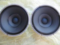
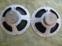
During BAF 2008 Jack Hidley generously handed out some 6.5” Peerless NPT-11-078-1 drivers, the subwoofer used in the NHT Super Two and Super Sub loudspeakers. I brought some home with me and would like to use them in a project. I am asking for design ideas and am sure other people will be interested as several attendees took home the same driver.
On Jack Hidley’s personal page at http://home.comcast.net/~jhidley/ there is a link to an Excel spreadsheet containing T/S parameters and related information for this and other drivers. Here is what it says about the NPT-11-078-1.

Part # : npt-11-078-1
Used in NHT models : Super Sub Super 2
Brand : Peerless
Size : 6.5"
Shielded : No
Basket : Steel
Cone material : Laminated poly
Re (Ohms) : 4.84
Fs (Hz) : 51.7
Qms : 2.738
Qes: 0.584
Qts: 0.481
Vas (l): 16.10
Cms (m/N): 0.000543
Mms (g): 17.4
Diameter (mm): 136
BL (N/A): 6.85
SPL (2.83V): 87.64
Zmax (Ohms): 27.6
Sd (m^2): 0.01453
Xmax (mm): 4.9
Hg (mm): 6.0
Hvc (mm): 15.7
Former material : Aluminum
# of coil layers : 2
Coil diameter (mm) : 32

Using Schiit LYR2 to drive loudspeakers - Bad Idea?

Hello,

I own a Schiit Lyr, that I don't use much and I was evaluating if I could use it as a low-cost amplifier for a couple of high efficiency 16Ohm/ch speaker.

This is my reasoning behind it:
The amp max power is rated 6.0 Wrms/channel @32 ohms.
Ohm's law tells me that 6Wrm@32Ohm corresponds to 13.9Vrms x 0.433Arms, which means I can safely draw from the ampifier output at least 0.433Arms/ch without sending its output stage in thermal runaway.

Let say I connect the 16Ohm/ch speakers, and protect the output stage with a 0.4A fuse, I should be able to 2.56W of pure class A per channel.

The output impedance of the LYR2 is 2.6Ohm, so I won't expect the damping factor to be that great, but considering I am gonna be driving very lightweight drivers that shouldn't be horrible.

Anything I forgot to consider?

IR2113 blowing ! help needed...

hi everyone,
I've been reading this forum for a long time but this is my first request...
I have made a half bridge class d amp not self oscillating, based on a 16MHz crystal and 4060.
the triangle wave is 700mV pp @ 250 Khz
the input opamp is TL072 (supply +-10V)
LM 319 comparator feeding a level shifter common base transistor

the next stage is 4070 and IR2113 to the N cannel Fet IRFP4227...
54uH and 470nF LC filter
post filter feedback

Power supply is +-80V 1kVA
IR2113 4070 are biased 12V over -80V

First power on no problem sound was great deep bass high frequencies clear but when i pushed it to clipping (symmetric at least !)

1 min after the 2 fet and IR2113 blow up

cooling was sufficient.

I don't know what happened please help...

Fets are not cheap and IR2113 blow every time fet do...

dac I/V convertion with very low distortion

This circuit dont use feedback, have 3,5 ohm of input impedance, and very low distortion , it gave only 0.000005% of distortion in the LTspice simulator at 2,5Vrms.


Yesterday, come to the conclusion that i need a new dac, so i will use the pcm1794 and dir9001, just because already have them.
I dont like the I/V of the pcm1794 datasheet, so i remember to use a circuit that i have design for a non feedback amp.

in attachment there is the asc file for the simulation. dont forget to go to control panel / compression , and turn off all compression for better visualization of fft.

if you have any doubt please fell free to ask 🙂

Attachments

  • dac1.jpg
    dac1.jpg
    235.6 KB · Views: 5,643
  • bod1.png
    bod1.png
    50.4 KB · Views: 5,294
  • iv1.asc
    iv1.asc
    4.7 KB · Views: 324

class A bias help

Hi

17y ago I biased in class A my op amps and was very happy with the sonic result. I used a trim pot and found the best sonic result for these to be at 2.4mA. So back then I biased the AD825 with one resistor and one 2SK170. OK, back then AD825s were very expensive and 2SK170s not !

I want to do exactly that again, still with AD825, but obviously the situation has changed. I have many AD825 handy, but no one would want to waist SK170s on that.

Could someone please point me in the right direction to get a suitable transistor replacement, non expensive and easy to get from Mouser, if possible leg / pinout compatible, and of course the associated resistor value so I get 2.4mA (under 15V) ? Having the right resistor value would help me ordering all the parts in one go, part of a bulk purchase at Mouser’s…

In short exactly the same but transposed in today’s world « avoiding the use of SK170 🙂

Many thanks for your kind help

Claude

BIB vs Tapered Transmission Line

Just a general question:

What is the subjective difference in sound quality between a BIB and a tapered transmission line? I know physical size is different... the tapered transmission line is smaller.

Both with the vent? out of the top.

HiFi Loudspeaker Design

vs

BIB - Speaker Projects

They look similar in construction... just the position of the driver relative to the closed end and the direction of taper is different.

Thanks! Forgive me if this is basic... just trying to understand the differences.
  • Like
Reactions: JBLutz

Rotary subwoofer baffle system

Just finished building my rotary subwoofer and it works quite well. One problem is however that it generates excessive wind noise which I would like to try to eliminate. I've heard one suggestion that includes building some form of baffle system that will absorb high frequencies manually well passing the very low frequencies that are being generated by the rotary sub .more or less a manual low pass filter. Can anyone share how this would be designed. Thanks

Replacement for Vifa P13WH-00-08

As the title suggest I am looking to replace the Vifa P13WH-00-08 drivers that are currently being used in the studio. Ive put great amounts of effort into searching around in different shops and forums for these exact ones, but with no luck. My coworker has grown quite a relationship with these drivers over the years so it would surely float my boat if anyone here is willing to share the knowledge they may have about close to identical drivers

Rotel RA-870BX Upgrade / Service help required.

Hi All

I have a Rotel RA-870BX which is having problems with one of the channels. Iv'e had to put it out of commission and go back to my old RA-820AX for the time being and my Tannoy 611's are not really breathing properly hehe.

Are there any service engineers / shops / forum members who would be able to help servicing the unit and possibly upgrading it, maybe replacing the old capacitors etc. I'm located in South Yorkshire.

Thanks in advance.

🙂

Cairn 4808A electrolytic film bypass mods remove or keep

Hi bought this amp last year and it had been messed with badly 😱
didnt work and had been fully recapped before i got my hands on it
replaced the regulators for the volume chip and got it back to as original as possible now working
the 6 bypass caps per channel have been added by whoever modded it in the first place
whats your thoughts ?
should i keep them or remove ?
Also if anyone can supply a schematic would be very grateful ?

20190724_132943 by glenn jarrett, on Flickr
20190729_135336 by glenn jarrett, on Flickr

Powered monitors line popping

I have JBL SLR305 monitors which always pickup pops when AC, fridge or dishwasher turns on/off. A loud pop. Nothing else or any other transformer based amps I have do this so I put it down to a cheaply made switching power supply in those JBLs which picks up noise from power line. I tried different sockets around the room, extended cord to other room but nothing has any effect.
Is there anything I can do apart from getting isolation transformer? Some years ego I had one which I used to eliminate ground loops but it was always buzzing when it was on which was really annoying in the room.
I read people talking about ferrite ring on power cord but I'm not too sure if that could do anything at all for mains power, possibly just a snake oil.

Martin Logan 8-inch driver specs

Just got a Martin Logan Voyage to use as a centre speaker (https://www.martinlogan.com/uploads/documents/manuals/manual_voyage.pdf).

But, I don't want it in the wall (as the TV is currently on a stand), so I'm building a box for it until we get the next TV. And, even then, I'm just going to build a thin box to sit below the TV so I get to use nice panels instead of sheet-rock.
The guys at ML provided a spreadsheet for sealed box design, and their thinking is that a standard in-wall mount (between studs) would provide about 75 litres (2800 cubic inches) of space.
So, no problem.

I was just wondering if anyone had the specs for the 8" aluminum drivers that they use? In case I wanted to port the final enclosure, or use a passive radiator, or even open baffle it. Mainly for interest. But it does appear that a much larger box would provide less of a peak in the midbass compared to the standard install.

Sanyo CD Transport from Candeias Modelo

Hi all,

I am desperately looking for a replacement board for a Candeias Modelo CD transport. It is from Sanyo and must have been part of their own CD players. The pickup is an SF-90.

Furthermore, it would be great if someone knows where to find more information on the Candeias CD transport. Unfortunately, one of the previous owners tinkered with it. A picture of the inside would help, at least.

Cheers

Marc

Attachments

  • IMG_5024.jpg
    IMG_5024.jpg
    710.9 KB · Views: 143
  • IMG_5022.jpg
    IMG_5022.jpg
    638.5 KB · Views: 119

Crossover help needed for Dynaudio 17W75XL(ohm) and D260

Current X-over.jpg

IMG_2360.jpg

View attachment Frequency Response-plot.pdf

I have Dynaudio 17W75XL {pn#84862}8 ohm mid/woofers from Dynaudio BM6A studio monitors [put into in 12 litre vented enclosure] and D260's tweeters out of Vision Acoustique model 702 speakers. I have worked hard on a very nice-damped/braced cabinet for these drive units. I now need optimum crossover design for this combination with high/low pass sections, respective zobels for woofer and tweeter (if recommended), maybe resonant or notch filters to improve sound and tweeter attenuation if necessary plus any phase corrections, etc. that might also help sound quality. Currently I have below configuration crossover that sounds good already and will rebuild crossovers a final time to live with the speakers forever upon getting proven ideal x-over spec and finally put this fun project to bed. Had based initial crossover design with attached theoretical plot with online "Speaker Wizard.uk" resource. Using Solen standard air core coils and polypropylene caps now but will consider Solen litz coils and Solen film/foil caps next time for final crossover build. Also using Solen achrohmic mil-spec resistors. Love the Dynaudio sound so far...!!!

Thanks in advance for any help!,
Gordon Hunsaker
Calgary, Canada

What is this behind Gregg Allman?

Hi all! I just joined the site as I'm getting ready to build some vented enclosures for a pair of JBL D140s I have laying around. :wave:

But my first post have nothing to do with that. I was listening to some Allman Brothers Band while working my day job from home and I noticed a strange piece of equipment behind Gregg Allman at 10:50 that I can't identify.

Anyone here know what it is?

YouTube

Measuring parameters on the cheap?

Spurred by some threads about loudspeaker break-in or the lack thereof (and let's please NOT get into debating that here:zombie:
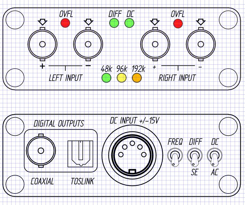
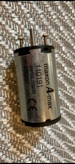
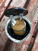
), I'm interested in doing some experiments for that. Which means I need to be able to measure resonance at a minimum, and all the parameters ideally. However at home now I don't have any equipment to do so*
--> What are some hopefully good and definitely inexpensive ways to do this?
I know the parameters change depending on how they are measured (for instance constant voltage vs. constant current) and versus drive level. I don't care about that too much, just something consistent.


*OK I could get a series resistor and probably generate a tone via smartphone and measure the voltage with my voltmeter Hertz by Hertz...😱

Please Help me to pick a best car audio brands

hi... been easily 10 years disconnected from playing with cars in general, recently retired in sunny thailand and would love to go back to tinkering and doing stuff with audio. Now it's not like all brands are available here when compared to the UK... but there are a few

I'm so lost hah. I ofc know all the OGs from the 70s onwards but some of them are now chinese owned? A/D/S used to be the **** now not so sure according to some sources.

I was looking on the pinned threads but theyre all 2011 and so on... googled car audio brands only some forums with also older info and this Top 10 Car Audio System Brands – Expert Review Blog monstruous list I haven't fully gone through yet.. I definitely don't know like... 50% of the brands on it..

I used to run the "posh" stuff, morel, focal etc... seems like those guys have kept their quality up though.

thanks for the tips

TM.

Loud popping noise with Classe Audio SIX pre-amp in phono MC mode

Loud popping noise with Classe Audio SIX pre-amp in phono MC mode


Loud popping noise with SIX pre amp in Phono MC mode.
Hello ,
I´m a proud owner of 2 very nice classe audio amplifiers.I have a Classe Six pre amp and a sevenhundred power amp.Both are very nice sounding, very musically amplifiers.I use it with Infinty Delta/Gamma speakers and sometimes with my good old Infinty Quantum 3`s.The TT is a LINN LP 12 with Lingo ,Manticore Magician arm and an Ortofon Jubille cartridge.Since last saturday I have a problem as follows:sometimes when I raise(or better when i touch) the Volume at the pre amp there comes a loud popping noise. The amp is going into protection mode (The red LED stays on continuesly) and comes back after a few seconds with light popping noise(DC at the preamp outputs around 180mV) .After a while it dissapears and everything is working fine.Maybe some forum members knows the problem or ad similar experiences with his pre amp.Maybe there´s something wrong with the phone stage?
I am thankful for every help I can get
with best regards

Western Electric 350B Beam Tetrode, or UL

Hi.

I am building an amplifier with WE 350 Beam Tetrode.

I have a dude.

In the datasheet , i can see , 16W output power with 18% of distortion , and 11 W output power with 10% of distortion. I think tetrode mode.

Can anyone imagine how many watts of that 16W or 11W could be used for audio.
In ultralinear mode could you lower the distortion ?

Santiago

Attachments

  • WhatsApp Image 2020-04-08 at 13.52.28.jpeg
    WhatsApp Image 2020-04-08 at 13.52.28.jpeg
    42.1 KB · Views: 178
  • WhatsApp Image 2020-04-08 at 13.52.28 (2).jpeg
    WhatsApp Image 2020-04-08 at 13.52.28 (2).jpeg
    110.9 KB · Views: 163
  • WhatsApp Image 2020-04-08 at 13.52.28 (3).jpeg
    WhatsApp Image 2020-04-08 at 13.52.28 (3).jpeg
    137.7 KB · Views: 164

Quarantine + spare MDF = Help me pick a design to build

I have some sweet MDF taking up space in my garage. I have some nice 1-1/8" panels that are 12" x 48" and plenty of 3/4".

Since I'm stuck at home anyway, I'm looking to fab some nice things. I don't need speakers. Not even sure if I'll get my money back if I sell them, but ever since I built my own C-notes last year I kinda have the bug.

Possibilities:
- Powered studio monitors since I am setting up a home studio
- tapped horn to stash under the couch for vibrating my butt when I watch a movie. My existing sub is surprisingly good down to about 25hz, so maybe something tuned to 20-ish to pick up some sub-sonic stuff?
- live performance monitors (powered or not)
- live performance loudspeakers for small venues (think like StagePass size, easily portable for jazz duo in a restaurant or guitar in a coffee shop.)

Is it possible to have a reasonable estimate of the Qms before assembling a driver?

I'm doing a design process (for myself) that starts at the desired application, choosing the enclosure type, delimiting the max dimensions and setting targets for the resonant frequency and the loudness.

Then I'll set targets for the T/S parameters and build a subwoofer with them in mind, so the obtained parameters will allow me to design an enclosure with the profile I want.

Noting that there are more limitations in respect to the driver: I have a chassis, two magnets and just a few options for the other parts; so I'll be mostly doing coarse estimates to choose the best combination.

But I'm affraid the Qms maybe too hard to estimate.

Without assembling everything I can use a weak glue or even tape to attach cones and spiders, place them in the chassis and estimate the Q factor by adding weights and analyzing the oscillation.

But I'm afraid that value is very different from the one I'll get after being properly assembled, because when assembled the resistance caused by having to force air around the coil increases dampening a lot.

Do you think the change in the Q factor due to this one factor is enough that even coarse estimates may fail?

Thanks!

Subwoofer question

Hello,

I have two questions one that is about subwoofers and another is about amplifiers. Let's get in to the detail about subwoofers and crossovers. I want to make sure that I'm thinking right. Here is two scenarios:
1) Subwoofer has a "Low Pass" filter at 150Hz;
2) Subwoofer has a "High Pass" filter at 30Hz;
I have statements that i want to make sure they are correct. First scenario with a "Low Pass" filter keeps the subwoofers voice coil from overheating. And second scenario with "High Pass" filter keeps subwoofer out of uncontrolled (depends on the enclosure) Xmax. Are they true if the power of amplifiers is constant in both cases and it's not higher than the recommended?


Another question that I'm concerned is about amplifier power and how it powers subwoofer. Let's say I have a way to measure amplifier power at 50Hz. I measure it and for example I choose to power my subwoofer @ 150wRms (in this case 20V). Everything that is below 50Hz will get less power and everything that is higher then 50Hz will get move power. Is this statement true?

My Hagerman Clarion Build - seeking advice from pro’s

For the last nearly 20 years I have dreamed about building an SET tube amp. It started in highschool, where I drooled over kits that I could buy and simply just build from detailed instructions since I had no electrical/electronics experience. I did build a Forepay pre right out of highschool, which I enjoyed building and listening to for years. I looked forward to building a 2A3 SET amp to mate it with. Of course relationships got in the way of funding, then marriage, kids, etc, etc...

Anyhow, I said “now or never. It is time to build something!” After searching around I came across Hagerman’s write up and thought this is excellent! there is a schematic, a parts list with part numbers, general information, I can do this. I ordered the small parts like sockets, plug, fuse holder, binding posts, inputs, etc., to lay it all out on the chassis. I liked how the amp was designed from parts that were accessible from one single supplier, however this meant being locked into those prices. Like many others, I’m sure, I am on a “budget” there is no cap per say, but I can’t set the wife alert off... I decided to go ahead and order the transformers through Edcor regardless of the bizarre 8 week build time.

The Hagerman Clarion Article

Fast forward to now: I received my Edcor high and low voltage and output transformer on Saturday. I am pleased I went that route, these helped my “budget” and will also look good. FYI their site says 8 weeks, but I received them in about 3.

As of today the chassis is mostly machined, I am drilling/machining it as the actual parts come in to ensure proper fitment. I will find a way to post up some photos soon. The only things left to machine are the power switch, volume pots, the necessary lamps, and mounting the chokes inside the chassis. That all is the easy part for me. The hard part, for me, is yet to come.

I started inquiring on the post Hagtech Clarion 2A3 SET I felt it would be better suited for me to start a thread of my own, for my own build. Where I can ask around for advice on my particular build instead of a 11 year old treat that has been silent since 2015

That is my back story, I hope some of you are willing and able to help me out along the way to complete this project of mine.

GZ34 rectifier capacitor voltage question

If I have GZ34 rectifier and 450V filter capacitors is it allowable to have AC voltage at GZ34 anodes with peak value above 450V?
I already have transformer with 2x 310V rms winding for GZ34, so peak AC is less than 450V. However, GZ34 is indirectly heated so when it start to conduct current other tubes will also start to conduct which means GZ34 is never operating without load so voltage on capacitors cannot reach peak AC (unless all other tubes are plugged out).
What do you think, is it possible to slightly raise AC voltage at GZ34 anodes to say 350V, would it be safe to still have 450V filter capacitors?

Need advice modding Grundig TK-14L

Hello!

I've had some success adding speed control pots and aux inputs to small dictaphones but I've recently got myself a reel to reel and I would love to add a few things to it. Problem is I'm a lot less sure with how to approach this and not break the machine, the internals look a lot more intimidating plus it's 220V here so I would really appreciate if anyone could offer some guidance?

Essentially I would like to do 3 mods:

- speed control

- reverse switch

- erase head switch


I'm not adept at electronics by any means but I'd assume the speed pot would have to be a 100k potentiometer wired to the motor or the motor controller?

To reverse the polarity of the motor I have a DPDT switch but I'm not sure where should I wire it to (the motor on this is 4-pole).

I'm also aware that disabling erase head will mess with the bias unless you switch it to a resistor of same impedance, question here is what impedance would it have to be and where would I wire it?


Thank you in advance for any help, I would really appreciate it!


Here's a service manual for TK-14, I assume it's very similar to the 14L (only one I managed to find).

WeTransfer

Alpine mrp-m1000 no sound

Hi, Im not getting any sound from my alpine mrp-m1000 amp. I bought this second hand around 4 months ago, tested it when I got it, fitted it to my car last week and had it working for about 2 hours in total over a few short journeys, then nothing. power light comes on and i can hear very quiet clicking sound from both subs.
I'm running 2x alpine swr 1242r subs (came with the amp)
I have checked all connections, tested rca leads, checked the total resistance of both subs which come to 4ohm at the amp terminals.
got good battery voltage, good earth and good remote.

Removed the amp from my car and took off the rear cover, havent tested anything inside yet as I'm new to this but I noticed one of the transistors seems to have got hot as the legs have a darkish tint to them compared to the rest (position Q4901, part number KDY 600K), the circuit board has a slight burnt smell too.

On looking in this forum it seems that a few people have had very similar problems but i'm not sure if they have managed to fix their amps as no-one has said it worked or not.

Has anyone got a service manual for this amp so I can possibly carry out some tests and get an idea of the figures I should expect to see? I may then be able to locate the failed part or parts and fix it before sending it to a repair centre.

My email address is dan66turner@yahoo.co.uk

look forward to any replies. thanks.

Issue developed in tu8600 re headphone plugging - help plz

Hi all

Ive had my tu8600 for two years and just today i noticed that an issue has developed.

For background - I use the amp as a permanent amp for my speakers, but occasionally plug in headphones.

The issue:
When the amp is on (but volume is turned down to zero) and i plugged in headphones today - i heard a crackle in the left channel during the action of plugging it in. Similarly, when i unplugged the headphones (with volume turned all the way down), i heard a loud pop/crackle from my speakers (again left channel). I haven't experienced this until today.

However, the amp works and sounds fine when in operation and playing through speakers, or playing through headphones where i turn the amp off before plugging in the headphones, and turn the amp off when unplugging.

Just wondering what parts might be at fault in order to fix the amp.

Many thanks for any assistance

Yamaha RX-V1900: 1v8 on SBR output

Hi.

In these Corona-times I have some time to work on this amp, but I have got myself a headache trying to understand what's going on.
The amp goes in protection, so I have to start it in self diagnosis.

There's 1v8 DC on Surround back right output.
I have pulled both OP-transistors and they measure OK. I have also measured the rest of the semis in circuit and compared them to the other channels.
Of course there are differences, but not more than expected, typical 0v552 - 0v562 drop or so.

Maybe the fault are located in the stage before the OPS ?

The amp are not easy to start up without Yamaha's extension cables, and one can't measure on OPS when the amp is assembled.
So maybe someone have a good clue about what is going on.

BR

Figge

Attachments

  • RX-V1900_OPS.PNG
    RX-V1900_OPS.PNG
    80.6 KB · Views: 108

Heathkit IP-17 ground and common outlet

Hi,

Just got a Heathkit IP-17 power supply.

front.jpg


I will use it to put together small "flea power" tubes amps for fun, tear them down and put together another one with a different small type of tube, etc...


Now on the Heathkit power supply, on the front, there is the + and "common" high voltage outlets for the amp circuit.

Also there is a Ground one by itself, should I tie the ground to the "common" outlet of the heathkit?

Since the "breadboard" will be an old tube amp chassis, should I use the Heathkit ground for the chassis ground?
I dont mind soldering and unsolderings the parts on the chassis and using it as the negative/ground of the circuit. Would be more solidly tied together since I might listen to the test amp for a while on 2 sets of speaker in two different rooms.
Also, I might fool around with some preamp circuit.

So in fact, my "experiment" circuit would be: the B+ , and the chassis on the negative/ground from the Heathkit.

Should I install a fuse on that chassis?

Just like a normal tube amp.

But then, if the Heathkit only has a two prongs AC plug for the 120 Volt from the main (didn't received it yet). Should I install a 3 prong AC plug?


Kind of funny, but I love to fool around with tubes amps, but I'm pretty scare of these high voltages, hence all these questions...
What would be the best way to go about it.

Any suggestions, ideas, objections?

P.S. I already built/restored a few Tube amps: 300B SE. Dynaco ST-70, ST-35, TubelabSSE, restored a Fisher 500C and a pair of QuadII.

Search the forum for this, didn't find much.


Type of circuit I'm looking at:
6CY7-SET-Amplifier-Schematic.png

Superphon Revelation Dual Mono - buzz/hum one channel only

My Superphon Revelation Dual Mono has developed a loud buzz in one channel, audible both line level inputs and louder on phono input.

Some background: I was testing some speakers and moved the speaker wires and interconnects during testing (preamp was muted at the time)
After this, the preamp immediately had a loud buzz in the right channel.
Signal is still present on the channel with the buzz.

This preamp is dual mono all the way to the (single) transformer. I've replaced the electrolytics last year (exept for the 4 largest ones in the power supply) and it's been working very well. I've checked for cold solder joints, but see none, the preamp was not moved/dropped etc.

I have an EE degree but have done little circuit level debugging since graduation 12 years ago (more of a software-related job). I do have a scope, DMM, L/C and ESR meters, etc.

So far I have tried isolating any bad components by tapping with a wooden stick but can detect no change in the sound when doing so. The parts count is very low in this unit, so I pretty much tried the tap test on everything. The large 1000 uF electrolytics in the PS are 25 years old but show no sign of leakage.

Can anybody think of anything that I can check? Where would you look first?

The schematic for the preamp is at http://www.diyaudio.com/forums/gallery/uploads/78563/Superphon_Rev_schematic.jpg.

I appreciate any suggestions you might have.

Bass Decibels

This is nothing to do with a build thread.

Anybody know of a subjective level chart for bass decibels?
I know loudness charts exists but they are mainly for high frequency sounds.
For instance 85dB in the highs might cause a slightly achey ear over time (think of a loud-ish bar with lots of conversation or a cranked TV set, or turning the stereo up a bit to do the vacuuming, or jamming with headphones at a "fairly loud" level) but 85dB of bass you could probably talk over. The level of bass rumble in a moving car is probably this much (assuming you don't have one of those really quiet posh cars)

I heard 105 dB of bass in a corner of a club in Coventry which sounded pleasing but not "loud". E.g. having free reign of a volume control and no one else wanting it quieter I would probably crank bass louder on my favourite tunes at home. Probably enough to go with the 85dB type level I mentioned above. The music was pleasant to dance to all night - not the fill your head with noise level and I want to leave and go to the bar after half a song and I have to shout as loud as I can to have a conversation level.

What level does "ear poppin'" bass happen? I've been assuming the level you can start to feel bass in your ears (as if going through a train tunnel, or the feeling you get closing the last door in a car) is in the mid 120s but I could be wrong (it also depends on the person's ears). I've got an SPL meter but it only does dBC and would probably pee off the neighbours during lockdown trying to test this. (Unless I can build a subwoofer cab I wear on my head with the mic inside it)

Ear tickling is around 120 apparently for strictly mids and highs (dBA), and 115 is about the level which goes right through you (think obnoxiously loud rock concert vocals you can feel tightening in your skull, or someone wanging a snare drum from a meter or two away).

Though if some of these enormous car stereos are hitting over 160 dB of bass within the confined space the woofers are used. If "ear poppin'" bass happens at say 130 and loudness doubles every 10dB then how are people sitting in cars subjectively 8 x the bass loudness you can feel in your ears? I mean imagine one of those old school receivers with the big dial from "0" to "10" and on "1" the bass is loud enough to feel funny in your ears and you still crank it to "10"! They don't seem to have earplugs in, or are they tightening the ears manually with muscles, or just stupid.

But saying "a Jet engine is 160dB" is meaningless because jet engines have unbearable squealing highs at 160 decibels (again imagine the big old school receiver where "0.5" is a really loud rock concert and between "1" and "2" is someone shouting into your ear and it's cranked to "10")

The one time I've heard "unbearable bass" was when I built an Autotuba and was testing for leaks inside the horn mouth. I put a plastic tube in the horn mouth and the other end in my ear but when I turned up the test tone, the bass travelled down the tube and was making my ear feel tickly. I took the tube out and could feel the movement of the air with my finger. It wasn't a good way to find leaks - only on the outside of the cab. Another is sticking my head in a Funktion one folded horn, you could feel bass in your ears as pressure and the kick felt like someone hitting you lightly in the head with the palm of the hand!

It's just people post of subwoofers doing 130 dB or whatever at 1 metre and I'm not sure how loud this is supposedly in the real world subjectively unless I can find a big open space to blare subwoofers.

For instance a Danley TH812 subwoofer can produce 148 dB at 1m, I assume this to be very loud but saying something like "this subwoofer produces a blocked ear feeling at 10 metres away" would give a bit of a real world though highly subjective indication.

I know this comment isn't very objective, but a subjective loudness chart for bass only (Frequencies from 25 to 75 Hz) would be useful.

Mini Aleph Build

I've been working on a Mini Aleph build over the last month or so and wanted to share my progress here to get feedback and also to hopefully provide some helpful information for future builders. And to be fair I should mention that the "last month or so" actually refers to the following build schedule:

2007 - Bought a LM3886 kit from Chipamp.com and on a whim added some Aleph boards to the order.

2008? - Placed an order with ApexJr for some other parts and remembered the Aleph boards so I added some transformers to the order.

2009? - I was moving and didn't want to move my 12" sonosub so I traded it to another DiyAudio member for some capacitors and heat sinks for the Alephs. In a major coincidence Variac was going by that person's house and offered to drop off the sub for me and pick up the parts. We then both forgot about them for a year or two and they sat collecting dust at his house.

2011 - At Burning Amp Variac and I talked and remembered the Aleph parts, but weren't sure where they were hiding. I had written them off as donated to another project, but a few months later they appeared at my office. Variac kindly included some large aluminum C-channel for the amp enclosures.

February 2012 - Over four years after I bought the Aleph boards I purchased the rest of the parts and started the build.


At some point I'll try to get around to doing a full writeup, but for now here is an overview of the build and some photos.

- The Aleph boards and the two power supply boards are from Chipamp.com. Using separate power supplies for a 10-15w amp is probably overkill, but since the transformers were $8 and I had the capacitors I figured why not.

- Matched Transistors (Q1/Q2) were purchased from tech-diy.com.

- Transformers are Signal BL1752 from ApexJr. Primary 230V -> Secondary 48VCT 7A & 28VCT 3A. Primary 115V -> Secondary 24VCT & 14VCT. I'll be running these at 115V and using the 24VCT secondaries which should hopefully give me 14-16v rails. For now I am not using the resistors in the CRC on the power supply boards, I may add those later after measuring the ripple.

- The rest of the components were purchased at Digikey or ApexJr. One great thing about Digikey is that you can add customer notes to your BOM which are printed on the labels, this makes things really easy when you are doing the build since you don't have to lookup which part is which.

- The most difficult part of this project has been figuring out how to get power from the power supply unit to the amp. I needed a 7 pin plug, but I didn't want to spend a ton of money. The plan is to use a 7 pin aircraft connector ($8 on ebay), though I have concerns that the pins will be too small for the 14g wire I'm using, we'll find out.

- I'm targeting a bias current of 1.2-1.4A since I will be using this amp to drive 4 ohm speakers, and because I have the heatsink capacity. For now the amps are built using fixed value resistors, but I have some precision trim pots I can substitute for R13 to adjust the bias.


That's all of the pertinent information I can think of at the moment. Please feel free to post questions, comments, suggestions, etc. I'm really looking forward to firing these up to see how they sound.

Mtx ta92001 distorted output.

Good morning DIY audio peoples it's been awhile since I've been on here and have a new project. Have MTX ta 92001 that has output but the LED lights on the top of the unit are not lighting up. the output is very distorted and staticy the first initial base hit of the music note played good, every note after that tends to wash out and sounds very staticky as if it's losing power open up the unit. The little corrosion by the large capacitors by the output terminals . also the two large inductors by the power input or buzzing really loud. LED light behind the RCA inputs are not lit up but the LED light by the output inductors top left corner are on. what do y'all think about issue might be? or where to start, the and work perfectly fine before the winter has been stored out in the garage in the Chicago weather for the winter time now this issue is present.
thanks.

Mysterious toilet paper shortage explained


MR Lundahl We know why there is a shortage of toilet paper
@lundahltransformers

Mysterious toilet paper shortage explained. Since the recent invention of the paper wound transformer, transformer manufactures worldwide have bought large quantities of toilet paper from local grocery stores. Unfortunately from what we have heard, the new invention has resulted in panic among people with more traditional toilet paper habits.


LIMP and Focusrite Scarlet 2i2

Hello.

I am trying to use LIMP with Focusrite Scarlet 2i2 ist Gen. The DUT is driven through an Amplifier

Please help me with the following queries:

(1) The Scarlet has mic , Line and Instrument level inputs.

Line In: input impedance is 10K and noise in presence of signal is -104dBu at min. Gain

Instrument In: Input impedance is 1Meg and noise in presence of signal is -87dBu at min. gain

Would it be better to use Instrument in or Line In and why?

(2) Limp manual suggests using reference resistor of 10 to 27 ohms. Professional systems use low value current Sense resistors. What would be the problem if I use a 0.47ohm or 0.22 ohm for the reference resistor. ( I am using an Amplifier to drive the DUT)

Thanks and regards

Altec 420A biflex -customized for Lampi OB

Pair of Altec 420A (Y) 15" alnico biflex drivers used in altec Santana and popularized by Lampizator in his monster P24 Project.( The designation Y comes from the version used with tweeters attached to the front basket which were removed) Like Lampizator I replaced aluminum dust caps with GPA (Great Plains Audio) sourced paper caps to tackle HF hash of aluminum dust caps. Since I don't have a room for big OB's (too narrow), I never built the speakers. I was holding on to drivers but even though they are becoming increasingly difficult to source they do pop up from time to time so there is no reason to keep them infinitely. I can send via cheap courier service to Eastern EU and most of the Western EU via Polamer shipping for ~$100. It will take 3-4 weeks and no tracking unfortunately.I will provide TS parameters . Drivers are in very good condition. $450

Attachments

  • IMG_4398 (1).jpg
    IMG_4398 (1).jpg
    973.9 KB · Views: 295
  • IMG_4400.JPG
    IMG_4400.JPG
    749.4 KB · Views: 285

DIY Analog-to-Digital Converter project.Audio measurements tool

Hello,


Does anyone would be interested by an high-end analog to digital converter ?
For my own use, i develop a new ADC .It's main use is a high performance measurements tool, for testing my DIY audio projects.
It's main features are :

Cirrus Logic CS5381KZZ 24 bits 192kHz flagship ADC
Fully differential and single-ended switchable analog inputs.
AC and DC coupling input switchable.
48, 96 and 192kHz on the fly selectable sampling rate.
Optical (toslink) and BNC SPDIF digital outputs.
Very small from factor (120x70x20mm)
Zero calibration allow all offset cancellation.
+/-10V FS input sensitivity.
Standard SMD or TentLab Master clock oscillator
Need +/-15Vdc power supply (SSR01/02 or other low noise PS. Allow 4 wires with sense connexions)
Use MAX3000 PLD functions controlling (no uC)
Allow low-cost or Scientific-Conversion High-end SPDIF digital transformer.

This is my 2nd ADC design (the first use the AK5394 ADC).
Here the PCB design use 4 layers with massive ground plane and very clean signal path routing
Now, the schematics and the PCB design is done, but not already sent to the PCB manufacturer.
I verify again and again each one before to order it.

If some DIYers are interested by this project, i can post more details about it.


Below, You can see what it should look like.

AA5381im1.jpg


Frex

Ultra low-noise regulators

I have some excess ultra-low-noise voltage regulators from a previous project:

TPS7A4700, Gone Mouser price 100 ea. is € 4.00. Asking € 2.00 incl. shipping wherever you are*.

TPS7A3301, 12 ea. Mouser price 100 ea is € 3. Asking € 1.50 ea incl. shipping wherever you are*.

Also some dual boost-buck switchers LT3471D , 10 ea. Mouser 100 ea. is € 3.30. Asking € 1.60 including shipping wherever you are*.

High current low voltage buck-boost regulator TPS63060, 38 ea. Mouser price 100 ea is € 1.80. Asking € 0.90 incl. shipping wherever you are*.

All original TI/LT, no 2nd source.

*If your total is less than€ 25 please add € 5 to share shipping.

Jan

Parasitic Oscillation

I have built an audio amp based on a Bob Cordell triple stage design.
During testing the one channel worked well with a sine wave input and just an oscilloscope on the output. However when I connected a speaker to it there was a severe parasitic oscillation on the output. Also the heat sink got really hot very quickly.
When I tested the second channel all I could see was parasitic oscillation when only the oscilloscope was connected.
I tried connecting a power supply to both units and only got parasitic oscillation on both outputs.
I have since found that the triple output design can suffer from this fault depending on layout.
Any advice?

Garrard 401 pulley replacement difficulty

Hi Chaps,

I recently acquired a mint 401 50Hz deck, my third in fifty years. I have a new 60Hz pulley but it has been impossible to loosen up the slotted screws in the old bottom collar, the top collar was easy. I have plenty of screwdrivers but as you can see in the photos they do not fit straight in the slot due to the angle and the tiny screwdrivers do not have the strength to do the job. I do not want to disassemble more parts.

Any suggestions will be greatly appreciated.

Horacio

Attachments

  • IMG_2926_resize.JPG
    IMG_2926_resize.JPG
    384.7 KB · Views: 290
  • IMG_2927_resize.JPG
    IMG_2927_resize.JPG
    292.5 KB · Views: 230
  • IMG_2930_resize.JPG
    IMG_2930_resize.JPG
    196.7 KB · Views: 229
  • IMG_2933_resize.JPG
    IMG_2933_resize.JPG
    320.1 KB · Views: 265
  • IMG_2934_resize.JPG
    IMG_2934_resize.JPG
    239.7 KB · Views: 218

Rockford Fosgate P1000-1BD No Rail Voltage

I have a P1000 that came in For repair due to not producing audio. I took the amp apart and checked the gate of output with my scope and noticed a small square wave was present on pad. I then checked the drain and realized it had 0 volts. I checked the power supply and it is functioning properly with nice square waves on gate and drain. I placed my multimeter probes on the center of the rectifiers and read 0 volts. The outter legs of rectifiers have nice square waves on them. I’ve repaired a couple of these but never seen them without rail voltage.

Attachments

  • 21421BAF-7C71-4C0A-BBF2-A25D4174C7D8.jpg
    21421BAF-7C71-4C0A-BBF2-A25D4174C7D8.jpg
    1 MB · Views: 153

Maxon turntable motor and controller boards

Hello all,
I have to sell a new never used Maxon 110191 motor (famous on the Teres turntable. Never used (its sitting in a box since a project that never came). Selling for 50€ (because it has a broken connector, half of the normal, but perfectly usable and solderable)

To sell also 2 brand new “Mark Kelly” controller boards by Sylvain Bergeron, 25€ each.

To sell one full set of the all BOM of components for building one controller, includes the Talema transformer, just had a battery and a box, and you’re done., asking 125€.

15€ courier for the full package.
Paypal accepted, let me know and I’ll send you an payment request.
Thanks for looking.

Attachments

  • F4F3A04A-FA13-483B-B502-A1C558B404F4.jpg
    F4F3A04A-FA13-483B-B502-A1C558B404F4.jpg
    119.5 KB · Views: 304
  • B93C6468-522E-4172-A8AF-9D76562B124E.jpeg
    B93C6468-522E-4172-A8AF-9D76562B124E.jpeg
    538.7 KB · Views: 264
  • D065E003-CCB8-4A9E-82B3-5F20D4ED870D.jpeg
    D065E003-CCB8-4A9E-82B3-5F20D4ED870D.jpeg
    930.1 KB · Views: 280
  • 209CC959-3703-4DFD-BC6F-579DA3F7DDAD.jpeg
    209CC959-3703-4DFD-BC6F-579DA3F7DDAD.jpeg
    664.4 KB · Views: 304
  • 42B0B16C-9D2F-4948-AF08-D85D50992FD6.jpeg
    42B0B16C-9D2F-4948-AF08-D85D50992FD6.jpeg
    904.8 KB · Views: 281

Hi to all!

Hello.
As you can see, this not my first post, but i have got questions, and i don`t know where to place it here.
So, i planning to build DIY Infinity Baffle loudspeakers, maximum a bigger for me modest appartaments, size of surface for each around 2m2, approximate 22 ft2. This very high sensitive - 97 db, not less.
On this moment i have one amplifier, tube, 4 watt class A on output 6P14P pentodes. I complete a satisfaction this amp, but i finding best.
So, my question is next: what amplifiers do i need to look at, or what features, or parameters, so that the amplifier perfectly conveys dynamic and macrodynamic sounds, such as explosions and shots.
I look forward to DIY kits sure, but possible of all variants.

Thank you, and be careful!

£50-£200 subs best choices.

There are a thousand ways to skin a cat and indecision is stopping me from making some subs.

Currently running full range drivers so looking for some stereo subs to handle low end, but can be crossed higher. Probably run Hypex Fusions for DSP/amps. Uk availability if possible.

Can anyone recommend (regardless of cab design, and can include any style but please include if they require certain design restrictions) the best subwoofers for for the below budget;

£50
£100
£200

Passive Radiators as Resonators?

I was wondering if it would be possible to reduce troublesome room modes with a simple box containing a passive radiator? The idea would be that the PR would be tuned to the room mode, and would resonate at that specific frequency in the location that it is placed.

Would it be best ported or sealed? Would it even be feasible? Seems like a low-cost alternative to a membrane resonator for low-frequency applications (and it would take up a *lot* less space than traditional absorption).

Stereo One Tube Amplifier 6C33C by Lansing Audio inc

Finally, someone has made a Single Ended Triode Class A amplifier with deep, powerful, extended bass and highs that extend to the limits of human hearing. Together with the traditional smooth and detailed SET midrange, this is the best sounding amplifier we have heard to date.

Here is a new Lansing Audio Brand 6C33Cls-8 integrated stereo amplifier. These are excellent sounding amplifiers with huge transformers.
This amp puts out some amazing sound and has more than enough power at 15 watts per side. It uses 2 tube 6C33C, 2 tube EL34 Driver and 1 tube 12AT7 pre. Quite heavy at over 105lbs.

Taking the advantage of technical knowledge and expertise accumulated to date researching for over 20 years being attracted and absorbed in premium analog audio systems, LANSING AUDIO has been producing the highest quality vacuum tube sound systems. LANSING AUDIO produces all the individual sound product custom built with hard wiring process by his own hands using only the premium class components in order to assure reserving the original high fidelity sound tone for a long period time up to the level of carrying the product for several generations.

For more detail, please visit us
Lansing Audio: lansing audio – Professional Sound System
Amplifier 6c33cls-8 :Lansing Audio Stereo One Tube Amplifier 6C33C High End SE Triode Class A, Driver EL34, Pre 12AT7 – lansing audio

Aikido 6SJ7/6SN7?

Just wondered if anyone has made a 6SJ7/6SN7 Aikido line stage yet. Remembering back to around 2003 John had designed a 6Au6/5687 line stage.
I made one and it sounded great. Yes, some would say too much gain but to repeat it just sounded so good.

This morning sitting here going thru threads I wondered if it was possible to make something a little different. I looked thru the info that was published years back and it listed different tubes and the respective parts and voltages. Not too much if memory is correct has been on the net about single front ends other than the 6Au6 that I can remember.

I was wondering if someone would join in the designing process and help me come up with something.

2 way portable speaker

Hello everyone


I've been given an old iPod bedside speaker (remember those?) and since it was not wireless, and I don't have an iPod, I pullet it apart. I would discuss about the electronics in it, but that's a post for another forum, so keep an eye out on that. What I am here for is for some general advice. The thing is, I ran these speaker drivers, which I have yet to mention are the Swan/HiVi C3N. They look fairly well, paper cone and rubber surround with a shielded magnet. I pulled up a spec sheet I found online for them and ran the parameters through a calculation software, in this case WinISD. For some reason, I tried 3 different enclosure types, for instance, I used sealed, ported, and passive radiator. The only problem is that for no matter what I do, I cannot get the -3 below 120hz. I listened to them in the old enclosure which was ported, and the highs werent "sparkly" but that's to be expected because they roll off at about 15k and there were no tweeters. I say the bass was pretty decent, perhaps around the 80db range at -3db. I have used WinISD many times in the past for various projects so I can admit it is not user error. I am thinking of using a passive radiator design, as well as some simple crossovers with maybe one or two tweeters. The usable volume of the enclosure I am going to make is around 0.1 cubic feet, which is the USABLE space. The enclosure is bigger, but since it is portable things such as batteries and electronics take up some space. I was planning on using passive radiator(s) as they are notorious for small enclosure where a conventional port is not viable. Take for example the Bose soundlink mini. I like it, other may not, but for what it is, and all the tech they jammed into it, it's a great background music speaker. I have a friend who has one and we measure an approximate bass response of about mid 70's at minus 3 decibels, which is fine for what I'm doing, though lower is of course better. Not to mention my design is much bigger at 0.1 cubic feet vs 0.5 liters for the soundlink mini. Any suggestions? Thanks guys.


Also, I can list the parameters if anyone is interested, or cannot find them.

decoupling the woofer driver // caps: zobel game ?

Hi,

the lytics caps // to the woofer in a passive filter are :

often lytics
always x00 uF capacitance
looks like more and more a mini-zobel as the ESR of the NPEs is increasing with years.

Should we bypass the lytics caps // to the woofer with film caps ?

I always seen 100 nF film // to 200 uF npe in commercial speakers for instance. Is it a real good idea to see such ESR mismatch for current flowing towards ground ? I mean the curent always flows toward the most easy path, aka less resistive... so is there a problem here like oscillation because of the ESR and capacitance mismatch with the // caps // to the voice coil Z of the bass - or mid- driver ?

Any rule like : bypass with 1% capacitance film a npe lytic the filter npe caps being between the plus and minus ?

Many thanks, not sure I can modelize that with Xsim like softs, would know more from members experience what happening at ears when designers choose it or used to. 😕

Hi all - nOOB with tons of questions :)

Hi all

I'm happy to be here and hauling from corona stricken Denmark.
Have build speakers before, but that is so long ago, and back then it was a more simple time.

During this time away from work, I have been thinking about a project that has been on my mind for years.

Having a female who is the boss at home, have sent several nice big speakers out of the living room. I'm lucky to have a Libratone Lounge in my living room... How am I going to rock to such a small thing? 😛

Anyways - the plans I have had for more than 10 years is this:
Sound furniture.

It seems so simple and yet it is giving me a gigantic headache!
I should have kept my huge amplifier and my gigantic speakers!

I'm looking for parts: How to get HDMI ARC in to the system, Adding airplay 2 and ofc, how get this proposed 2.1 system to accommodate both movies and music.

My parts list is nearing something that could be done, so I hope there is a few good people here, who want me to succeed 🙂

Bypass volume potentiometer (5 pin)

Hi
Can't get my headphones replaced in warranty during COVID lockdown so I am forced to fix the old ones.


I have a pair of old headsets that have this volume potentiometer that I would like to bypass entirely. And keep the volume full at all times.


Could anyone tell me which pins would I need to manipulate?
I have numbers the pins and shown which direction the potentiometer goes for volume increase.


Thank you

Attachments

  • IMG_20200407_124419.jpg
    IMG_20200407_124419.jpg
    259.9 KB · Views: 408
  • IMG_20200407_124322.jpg
    IMG_20200407_124322.jpg
    263.6 KB · Views: 515
  • IMG_20200407_124741.jpg
    IMG_20200407_124741.jpg
    299.2 KB · Views: 590
  • IMG_20200407_124311.jpg
    IMG_20200407_124311.jpg
    239.7 KB · Views: 642

SB15NRXC30-8 or SB17NBAC35-4 in 10 liters?

The 2 above drivers as modeled by winisd actually shows better LF extension from the smaller driver. The SB17 would go quite a but lower but needs 16 litres or so.
I have a WAF constraint and 10 litres is my maximum.

Would the SB17 subjectively give me more 'punch' , despite what the numbers say.

I remember a quote from Zaph or Troels maybe who said you cant substitute SD and would always go for a bigger driver where possible...(was referring to 5.25")

These drivers will be used as low as they can, although I can filter out the lower octaves when listening through the Denon AVR, critical listening is straight from dac into DCG3>power amp>passive speakers
Projects by fanatics, for fanatics
Get answers and advice for everyone wanting to learn the art of audio.
Join the Community
507,723
Members
7,885,825
Messages

Filter

Forum Statistics

Threads
406,120
Messages
7,885,825
Members
507,723
Latest member
semajbab