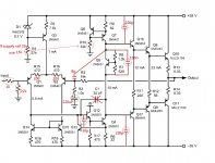
I have built an audio amp based on a Bob Cordell triple stage design.
During testing the one channel worked well with a sine wave input and just an oscilloscope on the output. However when I connected a speaker to it there was a severe parasitic oscillation on the output. Also the heat sink got really hot very quickly.
When I tested the second channel all I could see was parasitic oscillation when only the oscilloscope was connected.
I tried connecting a power supply to both units and only got parasitic oscillation on both outputs.
I have since found that the triple output design can suffer from this fault depending on layout.
Any advice?
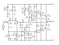
a schematic for those who wish to help but don't have the book handy would be helpful.
that being said, a couple of things to check for:
if it is all BJTs, do you have small resistors (10ohms or less) at the base of outputs and drivers?
if it uses MOSFET outputs, do you have large enough gate resistors?
and are those gate or base resistors very close (with short paths) to their respective devices?
do you have decoupling caps of "appropriate" value placed "correctly" with short ground paths?
are you using long leads to connect the source to the input?
are you using long leads to connect the load?
do you have the R-C network on the output? (I'm guessing not - I think you would smell the resistor getting warm with parasitic oscillations!)
schematic and complete pictures of your setup (so we could see the wiring and gauge distances) would help!
so would scope pictures of the oscillations; the frequency would provide some additional clues...
good luck!
mlloyd1
The book can be downloaded as pdf for free, even so I don't want to put schematic online due to copyright.
Output transistors are MJL21193/MJL21194 BJT's
Only have 10R resistor plus 100n cap at output.
About .5m lead on input.
3m lead on output.
No decoupling caps.
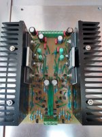
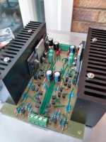
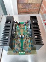
Will try and get suitable photos
Output transistors are MJL21193/MJL21194 BJT's
Only have 10R resistor plus 100n cap at output.
About .5m lead on input.
3m lead on output.
No decoupling caps.
Will try and get suitable photos
I am quite certain that the "free PDF download" you mention IS a copyright violation.The book can be downloaded as pdf for free, even so I don't want to put schematic online due to copyright.
That said, MAYBE a cropped, incomplete section of said schematic, showing only the relevant parts, say output transistors, Zobel/inductor (if appliccable) and NFB network COULD be acceptable or fair use for specific Servicing purpose.
Not sure what Moderators say in that specific case.
Of course, please post YOUR pictures of the build.
I trust the circuit itself is fine, but actual implementation is anybody´s guess.
- Status
- This old topic is closed. If you want to reopen this topic, contact a moderator using the "Report Post" button.
- Home
- Amplifiers
- Solid State
- Parasitic Oscillation