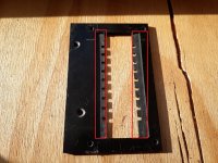
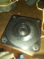
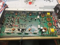
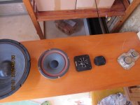
Vertical Corugated tweeters

Here are 2 videos about me making a weird tweeter i had in mind for quite some time. its a live stream... so i would 100000 percent understand if you would not watch all of it 🙂 haha its so long , since it is real time 🙂

VIdeo 1 live
YouTube
Video 2 live
YouTube

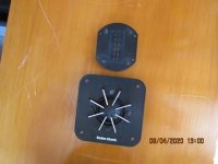
but its is a sort of planar/ribbon it combines the 2 things i like most 🙂 ribbon for low resonance and easy crossover, and planar magnetic (normal one ) in terms of magnet layout. and method of being able to create some really weird coils 😉 and still have a rather OK output without trannie and small height to have semi ok dispersion.


Hunting down weirdness in my tweeters. i am rather happy so far but when i put it in Push pull i get a weird dip (it was also present in single ended but harder to notice)


Biggest problem was a wiggle at 10Khz when i used it in push pull and also some weird dip at 4 khz in both. a nice thing is this tweeter has a resonance of around 100 hz or something so very easy to crossover 🙂


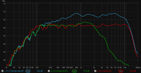
All measurements are gated @ 3ms and use 1/12dB smoothing

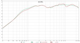
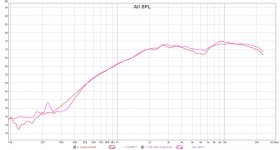
Pic 1 Push pull vs single ended in the mini monitor baffle.

you can see the weird dip clearly, a dip at 4 khz and a huge swing at 11Khz

Red Push pull
Green Single ended

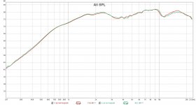
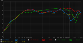
Pic 2 Push pull vs push pull without any magnets on the front, i adjusted the volume. to see whats going on. so apparently the magnets is not creating this.

Red with magnets
Green Without

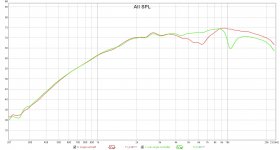
Pic 3 I removed the tweeter and used it free air.

push pull vs single ended

Purple Push Pull
Red Single ended

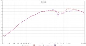
Pic 4 tweeter still out of the baffle , this time the front (that does not have a frame to hold the tweeter) vs the back

Red Front
Green Rear

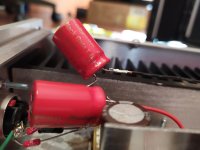
Pic 5 i wondered what the frame thickness did so i added the frame that is there when using it in push pull and made it 4 mm thicker then it usualy is.

Red default 4 mm frame
Purple with an extra thick 8 mmm frame (no magnets in the front just the frame)

Pic 6 I still am not sure if it is damping or the width of the cut out need to make a new frame for it, but here i added felt and the red marked spots.

Pic 7 The result with felt in single ended without baffle

Red without felt
Purple with felt

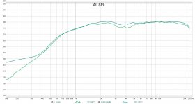
Pic 8 Now its time to put the single ended in the baffle and see what we gained.

Light green single ended in baffle
Dark green with felt mod in baffle.

That looks promising to me. almost as flat as i could wish for. question still remains is the damping needed there or should it make the cutout of the frame as wide as the driven area. ? adding felt makes it possible to get lower resonance, making the cutout in this case smaller (since it cant be wider then the magnets without creating the same problem) might result in the same and is easier to produce. less parts less work etc etc. well i guess i need to try both. so far felt DOES makes it allot smoother almost perfect.

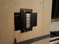
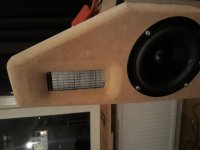
Pic 9 just the tweeter in push pull on a test baffle, measurements taken in this post where my mini monitors baffle

its amazing how the plot can change with some minor crap

Attachments

  • 01 Push pull VS single ended in a baffle.jpg
    01 Push pull VS single ended in a baffle.jpg
    135.6 KB · Views: 248
  • 02 PP in baffle withouth any magnets just the frame.jpg
    02 PP in baffle withouth any magnets just the frame.jpg
    133.6 KB · Views: 245
  • 03 tweeter PP and single ended without baffle.jpg
    03 tweeter PP and single ended without baffle.jpg
    135.4 KB · Views: 242
  • 04 out bafffle single back side vs front.jpg
    04 out bafffle single back side vs front.jpg
    137.5 KB · Views: 239
  • 05 pp frame but made the front fram 4 mm thicker.jpg
    05 pp frame but made the front fram 4 mm thicker.jpg
    135.2 KB · Views: 239
  • frame.jpg
    frame.jpg
    748.2 KB · Views: 140
  • 06 in single ended with felt in the frame va no felt.jpg
    06 in single ended with felt in the frame va no felt.jpg
    149.9 KB · Views: 136
  • 07 felt in frame single ended in baffle vs no felt.jpg
    07 felt in frame single ended in baffle vs no felt.jpg
    141.9 KB · Views: 105
  • 20200410_000040.jpg
    20200410_000040.jpg
    643.7 KB · Views: 168
  • 20200411_220353.jpg
    20200411_220353.jpg
    763.9 KB · Views: 188

Driver power difference

Hello

I am currently designing my first speaker. It will be a 3-way passive with Seas drivers. As I want the best of all worlds I've decided on a TL (Sub) woofer and sealed midrange for good transient response and decent low end extension. The drivers in question are:

Tweeter: 27TFFC

80 W
91 dB

H0881-06 27TFFC

Midrange: ER15RLY

60 W
87.5 dB

H1455-08 ER15RLY

Woofer: XM-001-04 L26ROY

250 W
87 dB

XM001-04 L26ROY

As you can see, the ER15RLY is quite underpowered compared to the two others. I am thinking it will be crossed at around 150 hz and 2.5k hz. Which means it'll be in the freqency range were it will need to be relatively powerful. Am I right in my two options then: either use resistors on the woofer and tweeter, therefore never reaching the potential of them. Or use a more powerful mid range (larger/two drivers)?

The Best B+ Supply

Hi Guys,

I hope I am posting this in the correct place, I think this question is better here than in the tube section. I am interested in the question of the best available B+ supply for a tube preamp. What would be the 'state of the art'? what would be the highest performance per dollar spent?

Firstly, the amp is a kitset Aikido design using 6SN7 tubes from an USA based online retailer that is not Broskie.

I am in the process of rebuilding the amp entirely as I have had some issues that are most likely due to the poor quality of my initial build many years ago.

Since I am planning to do a clean sheet rebuild I am considering whether the current PSU is ideal.
Here is the current power supply:

Preamp PSU current public 2.jpgIs there anything less than ideal about the current supply?
Is there something higher performance that might be built for similar or lower cost?

Other options I am currently considering

1) A Maida style regulator, either with a mosfet a la Pete Millet or with a 10M45S a la Broskie.
Is this going to be higher performance than the current offering?

2) Salas SSHV2. shunt regulator.
This seems to me to be the highest performance option.

3) Jans HV regulator.
I'm not sure where this would fit in performance relative to the SSHV2.

4) Back to basics with a high quality CRC or CLC filtered supply.
Some say still the best option?

5) Janus Shunt Regulator from Broskie.
Problematic due to space requirements.

Are there any other good options I have missed?
I am concerned here mostly with the B+ side.
I am inclined towards solid state rectification and regulation as it requires less maintenance and ultimate less space to implement.

Noisy USB ports?

Greetings. Posted a question earlier about a sound card for my budget basement sound system. I have since bought an ASUS Xonar U7, which has good specs and measured well at the audiosciencereview site. Hooked it up to an old desktop computer and power amp and was disappointed in the amount of computing noise I heard. It was down about 60dB, but extremely noticeable due to the noise characteristics. After playing around with ground loop elimination I eventually realized that the USB ports themselves seem to be noisy. If I plug my headphones directly into the sound card (no amplifier/speakers), I still hear the noise. Tried different USB ports but they all have the same issue. If I use my laptop, the card is dead quiet. Looked at some USB filters, but the commonly available ones only support 12Mbps, which is not fast enough. I have a free PCIe slot and wonder if a $15 USB card would resolve my issue. Any thoughts or other ideas? Thanks.

I'm getting good at this, pt1 : Killed a Hafler DH-110 preamp

I finally got my parts order from Mouser to get my DH-110 back in play.

Original symptoms: loud, dangerous crackling when I used the volume control. Teardown revealed complicated ALPS volume control. Visual inspection of the board revealed "pillowing" in the tops of the power supply caps. Also revealed was that two of the heat-sinked BJTs on the board were missing their heat sinks.

I purchased Nichicon audio grade parts to replace the supply caps. The new caps are practically tiny. The filter caps the size of the old bypass caps, and the new bypass parts require magnification to work with. And thats after bumping up to 105c from the original 85c parts. Every kit I see online for the preamps use caps the same physical size of my original parts.

Thats the first sign I did something wrong. But typical of me, I forged ahead.

I installed the new caps, making sure I had the polarity right. I replaced the missing heat sinks. I also tore down the ALPS rotary volume and treated it and the other pots with D5.

With everything installed, I plugged the preamp in and hit the power switch. Two red lights appeared on the front panel. Success? That doesn't seem right.

I reassembled the preamp and took it upstairs to try out on a system I'd just thrown together for kicks. With it plugged in to everything, I hit power and.... nothing. No red lights. The preamp is dead. Ah, thats more like it! If I actually fixed something the world might start rotating backwards.

Interestingly, if I crank up the volume knob I got a very faint crackle out of the left channel, and I could get glimpses of the music coming out of the CD player.

DMM shows 125v at the transformer and at the volume switch. What do I look at next?

  • Locked
Why wouldn't this work?

I'm toying with idea of building a 3-way system in the form of a near cube (just for kicks). Say, 250mm H x 200mm W x 200mm D. With X-Over frequencies @ 250hz & 5kz.

The bass driver is a 6.5" down-firing sub-woofer. (Set at 30 degree angle). The midrange unit is a 6.5" forward facing bass-mid driver. And the top is provided by a dome tweeter.

The idea behind the low x-over frequency and the oversized midrange unit is that the mid-unit also serves as a passive radiator for the bass unit.

I'm not looking for a flat frequency response but can somebody explain why it wouldn't work?

Naksa 80 Input GND question?

Hi,
Inside of the amp

An externally hosted image should be here but it was not working when we last tested it.


I have a green wire connected to the central earth ground at one end and not connected to anything at the other end.

An externally hosted image should be here but it was not working when we last tested it.


Looking at the inputs connection to the board, Hot and Gnd seems to be correct.

An externally hosted image should be here but it was not working when we last tested it.


Per manual, the wire (pointed) label per manual says "RCA Ground to Star Earth PCB"

An externally hosted image should be here but it was not working when we last tested it.


Should I connect the green wire to the GND of the L and R input RCA's then? I do have some hum (one source, one preamp, 94 dB speakers). Other amplifiers does not exhibit the hum.

Thanks for any help.
Abe

Marantz PM66-SE - need help to identify a resistor

Hi,

My trusty amplifier has burnt one resistor (my fault because I reconnected some wires in the wrong position). I have photo of the board before, but the quality is bad and I cannot be sure of what type of resistor it is - the colors are not clear in the picture.

IMG_6061.jpg

I would love to have the service manual for this amplifier. Can anyone e-mail it to me? My e-mail is joaquimfonseca@netcabo.pt

If this resistor has burnt what are the chances that other parts have also suffered? What else should I check? I guess that the cables that I reconnected on the wrong position are one of the 2 in the pictures.

Capture1.JPG
Capture2.JPG

Thanks,
Joaquim

Phillips AD12202/m4 Belgium. Pair

I have 2 12" Phillips open baffle speakers and 2 Phillips soft dome tweeters. Made in Belgium. I was going to make a pair of speakers, but I got sick, there like new condition, I looked around for these, and got them for there like new condition. I will take 200.00 for all you pay shipping.

Attachments

  • IMG_20200417_123143720.jpg
    IMG_20200417_123143720.jpg
    323.1 KB · Views: 161
  • IMG_20200417_123204641.jpg
    IMG_20200417_123204641.jpg
    385.3 KB · Views: 135
  • IMG_20200417_123232442.jpg
    IMG_20200417_123232442.jpg
    510.9 KB · Views: 136
  • IMG_20200417_123243015.jpg
    IMG_20200417_123243015.jpg
    723.1 KB · Views: 140

Soundstream RubiconA4 repair

Hey there,

Picked up a Soundstream RubiconA4 to mess around with and see if it can be repaired. I have had no luck finding a service manual. Powered up the amp and the power light fluctuates from bright to dim red. The amplifier produces no sound. Opened up the amp and noticed one of the screws that clamp the board to the heatsink was loose, the screw will not tighten, seems the heatsink is stripped or was tapped improperly from the start. That can be addressed if the amp is functional and when the board is removed from the sink.
Test point TP9 reads 0VDC, TP7 +12.3VDC, TP8 +11.7VDC, TP 10 +Rail fluctuates between +8-12VDC while TP11 fluctuates between -8 - -12VDC.
Hopefully this is an fix

Thanks for your time

Attachments

  • 8F09F71C-9BF5-414D-A785-E265059BE2BA.jpg
    8F09F71C-9BF5-414D-A785-E265059BE2BA.jpg
    1 MB · Views: 145
  • 6C69F3F9-ED77-433F-9AC1-04B040DCBB61.jpg
    6C69F3F9-ED77-433F-9AC1-04B040DCBB61.jpg
    919.5 KB · Views: 115
  • 63048439-6E6A-4B85-93FE-3BADD2D83D6C.jpg
    63048439-6E6A-4B85-93FE-3BADD2D83D6C.jpg
    1,004.3 KB · Views: 131

Caps powered amplifier?

In my search for new knowledge, did I visit one of my favorite YouTubers: learnelectronics and saw this video YouTube about super caps and batteries.


Many years ago did I here about some trying to build a battery powered "passive" preamp with an Elna stepper attenuator, and then did stupidity struck me! 🙂
Why not build an amplifier that uses two sets of caps, one set is being drained while the other set is being charged, and when empty, it switches caps-set. In that way would it work just like on batteries, totally floating from any mains.


I know sins I can think of it, hundreds of other may have got the same thought and decided it to be to stupid to use! So why is it a stupid idea? 🙂

Testing with a resistor in place of OPT

For very initial testing I'll be working with power supplied running though a light bulb to current limit. I've also thought it may be easier to use a high wattage 5K resistor in place of the OPTs. This will make it easy place to measure waveforms and current. Obviously this doesn't completely mimic the OPT/speaker combination but is there any issue with using this approach?

Russian Tube Markings

Aside from the well known СДЕЛАНО B CCCP (made in USSR) and OTKxx markings there are often more such blue stampings:
- a one/two digit number in a diamond - I've seen numbers between 0 ... 23
- same but in a pentagon
- and just recently a batch of newly aquired 6С19П-В show a "Э" (ee) like a mirror image Euro sign in a circle.

What do the numbers inside the diamond or pentagon mean ? does somebody have a list ?
I vaguely remember a posting by @Wavebourn who mentioned these indicating the intended service in military equipment but I cannot find it anymore.

What's the difference between the diamond and the pentagon ?

And what does the Э in a circle stand for ? I hope it does not mean "scrap" or "reject".

Here are some pictures.

Attachments

  • IMG_0495a.jpg
    IMG_0495a.jpg
    65.4 KB · Views: 206
  • IMG_0499a.jpg
    IMG_0499a.jpg
    94.6 KB · Views: 207

Broken TP3116

Chaps can anyone pls help me out here. Not knowing anything about this sort of stuff, I've been given a TP3116 amp which has a potentiometer snapped off. Assuming that is all that is wrong with it, I'd like to get a replacement soldered in but dont know what exactly I need to order. Anyone able to enlighten me?
(See.....I told you I knew very little about this stuff 🙂 )
Grateful for any assistance


Untitled - Google Photos

Pentode buffer power amplifier?

Hello guys, Ive found this circuit on the web. What do you think about it?

tube_unity-gain_buffer.png
It has 100% degenerative fedback which will extend frequency response and maybe make the bass control better. But do someone have some personal experience with this circuit? I can build it with 6P15P russian output tube.

I played all my life on single ended triode amplifiers with no feedback. Im a little bit scared that this circuit will be too accurate and flat sounding...
I have no idea how this can sound.

But for example regular cathode follower also is 100% degenerative feedback and this play in my system very good.
Now I have a 2W 45 SET amplifier.
Thank you for replies. Michal

PVC sewer pipe speakers

I've been searching for some designs with PVC sewer pipe, and would be interested in any designs and listening experiences. In terms of options we have commonly available (all internal measurements):
110mm - for CHR-70, Alpair 7, Fostex 103E etc
160mm - for JX92S, Alpair 7, Fostex 168E etc
200mm - for Alpair 12, Fostex 208E etc

There are various accessories as well - T junctions, 90 deg. bends, stoppers, access pipes etc which would facilitate a speedy construction.

The other interesting possibility is to put a pipe within a pipe and fill the space between with sand. So 110mm inside 160mm, 160mm inside 200mm, 200mm inside 250mm. Should be pretty inert!!

So how to proceed with this? I can't see it being possible to taper the pipe, so bass reflex is an obvious option. But what could I do in terms of a tuned pipe - ideas?

andy

How important is it that monoblock power transformers are identical?

I want to use two identical mono amplifiers salvaged from 1960's consoles as a pair of mono amps for stereo use. From there, to improve and adapt them as a test-bed. Should be a fun learning experience.

However, one half of one of the power transformers to be complete open-circuit. If I can't quickly find another identical chassis/console, I can buy a similar, generic small-amplifier PT for about £50.

So... is it sensible to just buy one transformer, or should I replace both?

(What I'd really like to do, of course, is catch another console on its way to the skip 🙄

Cheers

McIntosh 4 channel amp, uneven rail

I have this amp for repair. Changed a lot of caps, because of leaking. On one side I have +29,5Vdc, and 28Vdc.
On the other two channels I have 37v and 20v..the input on the power supply transistors are equal. Also the input of the rectifiers are equal. I removed nearly all parts, still the same.
The amp draws in this star 1.3 amps. Goes straight in protect. So I removed a diode, to keep the ps on.

Attachments

  • IMG_20200416_155250.jpg
    IMG_20200416_155250.jpg
    997.6 KB · Views: 150
  • IMG_20200416_155253.jpg
    IMG_20200416_155253.jpg
    986 KB · Views: 124

Ground plane measurements results (good and bad)

I have managed to spend some time outside measuring speakers lately, have gotten fantastic results measuring midranges, and would like to share my process (active system using MiniDSP).

  1. I use REW and variable smoothing 95% of the time. Sometimes I will use 1/24 to make sure I am not missing something important, and then I switch back to variable so I can work with the important trends.
  2. Take ground plane measurements at different distances. You want to be close enough to see a nice straight response without excessive smoothing, but far enough away that directivity does not kill the top end. If you are too close or too far away, you will see the response curve or ripple too much to be useful. I find 4ft to be a good starting place.
  3. Take far field measurements on the design axis at different distances. I like to start at 2x baffle width and increase the distance until ripples compromise the measurement above the point I think I want to merge to the ground plane.
  4. Overlay and align the two raw measurements' SPL, and make sure their IR peaks are aligned.
  5. Merge (with blending) just before the GP peaks and drops away (which is right at the point the farfield ripples get confusing) = ~700Hz for my 10” wide baffle
  6. EQ (IIR) the response down to flat (in REW) as far as practical to either side of the intended crossover frequency.
  7. Take a far field measurement to confirm the measurement matches the predicted EQ response. Start at 2x baffle width and go back as far as you can before you lose site of the trend (measuring outside, I stop at 6ft). The response should stay flat and not curve in the middle of the passband.

In the first attachment, you can see the blue midrange GP + farfield merged measurement I used to create the EQ. In green is a GP measurement I did with EQ, and in red is a 30" farfield measurement to confirm that both the merge operation and EQ are correct.

I can run through this procedure in 10 minutes if I’m lucky, or an hour plus if I interpreted the merge wrong and have to rethink it or measure again. I consider this result just about perfect, and didn’t have to model or account for the baffle step at all.

Here's my problem: this process does not work for my stacked woofers near the floor. Ground plane measurements suggest a baffle step, but using my process results in far field verification measurements with a downward sloping response, with the mic at any height or any distance. In fact, the only way to get a good final response is to assume there is no baffle step at all.

In the second attachment, you can see woofers on the design axis in blue, the mic at the same distance but woofer level in red, and GP in green. Notice the dashed yellow nearfield measurement seems to be a mirror image of the groundplane for most of the passband. I know the (too small) box alignment is not canceling out the baffle step, but leveling the GP measurement is going to do bad things to the other traces.

I don't know what I should try next.

Attachments

  • 411 M EQ process.png
    411 M EQ process.png
    46.6 KB · Views: 616
  • 414 W comparison.png
    414 W comparison.png
    66.8 KB · Views: 592

TL sub project

hi all

TL doesn't mean transmission line but about thailand sub last week my friend bought new imf hp-15w(2011 version) will use in home sub. i try to sim will ok 139ltr. low freq respond will boost about 50 db, ok can eq it to flat. after he did finish. listen to with song. wow! very bad. and hope that it was like this. lol he would burn it. and he went out of home about 2 hours. and after came back , he didn't believe . wow ! the bass was better than at first start very much. he felt satisfy it. cheap but not bad. hope that burn in about more than 20 hours will be good more than this.. but with i .. not happy. PeteMcK ever told me "thawach p audio imh hp-15w sale in tl about 1200 bath" . ok friend last double years i bought . don't sure the parameter. when i see the 15w in utube. i see the cone, the both cones look difference. my cone seem cover the plastic(pvc). i bought before the new version 2011 get out to sell. if i use the old spec. it will be sure? someone try to think with me. now still don't do any box with it .ahh

hp-15w - YouTube


Crossover - Placement of Component

Hello Everyone,

I’m about to embark on my first speaker project and needed some help with the placement of crossover components.

Most commercial and DIY speakers have all the crossover components on a board fixed right behind the binding posts; but there are also small number of speakers (eg. Epos ES14) have very simple components (usually just caps and resistors) fixed right behind the drivers.

There are some discussions about keeping a decent distance (~15cm) between the inductor and the nearest driver, not I’ve not read anything about the “safe distance” for capacitors and resistors, nor if there should be a recommended “maximum distance” between the inductor and capacitors / resistors.

As I have quite limited space behind the binding posts where it is the furthest point from the Drivers, I’m just thinking if it is wrong mechanically / electronically / sonically if I place only the inductor behind the binding posts while the capacitors and resistors right behind the driver?

Many thanks.

FS: Blackgate NX 1000uF

Hey all,

Took apart a headphone amp (it was a DoZ) I built a while ago, and found 2 1000uF (25V) Blackgate NX caps. The amp was lightly used, as I built a Minimax amp soon after.
I've also got another 2 from a DAC project (also lightly used).

I've seen these for sale on ebay for $340USD a piece (used).

How's $120 a piece sound? $400/lot

The caps measure as follows:

1067uF
1111uF
1081uF
1038uF

They all have an ESR < 0.016 ohm

I've also got 2x 10uF 50V Blackgate N (which measure at 11uF each - ESR ~0.22 ohm each).
$50 each (based on a $70 price currently seen on ebay)

Images of measurements to follow

Attachments

  • IMG_20191111_075303.jpg
    IMG_20191111_075303.jpg
    223.5 KB · Views: 831

Chip amp temperature

I put together a small amp with the LM 3886 chip and it is currently powering my AR3A's which are 4 ohms. The power supply is putting out 28 volts +- and the unit operates without noise or any issues so far. I do not listen at very high levels and wanted to find out the current temp on the chip and the heatsink. The laser temp gauge indicates 95 F on the chip about 100 on the heatsink after about 3 hours of normal to moderate volume levels

My concern, after reading some threads that running 4 ohm speakers is not a good thing with these chips, is are these temps too high and will there be issues and possible melt down.?. I do have 8 ohm speakers to substitute and will do that to see the difference in operating temps.

Anyone have any advice on this? Thanks for the time Cheers Wayne

Dongle driver problems ATB PC Pro

Hello,

It's been a long time since I did anything on the DIY grounds.
I'm trying to pick up from 2013, but a lot is lost from memory.

In Windows 10 Home edition, I can't install the ATB dongle driver, because it's not certified, not digitally signed.

I've tried 4 different ways to overcome this in Windows, no luck...

I really would like to start learning the measurement program again and get back on the DIY-train.

thanks!

What's wrong with astable multivibrators?

Hi all,

I've been interested in class D for a while now and have been wondering how simple they can get. Simple in terms of discrete transistor count, no ICs.

This lead me to various differential pair circuits like comparators and astable multivibrators. Following that trail took me to some old patents such as this: US3445788A - Pulse-width modulation circuits
- Google Patents


I know part of the motivation and benefit of the UcD is a low discrete parts count. An astable multivibrator with variable duty cycle appears at first glance to fit the bill, but they obviously have some fatal flaw, otherwise they'd be common - that patent was filed in 1966. I'm sure the short answer is poor sound quality.

Can anyone explain some of the technical disadvantages?

Thanks!

Attachments

  • US3445788-drawings-page-1.jpg
    US3445788-drawings-page-1.jpg
    418.6 KB · Views: 143

Behringer PMP4000 Distortion and low power

Hello. I have a bit of an issue with my powered mixer. My Behringer PMP4000 has an issue with output. The sound is very under-powered and distorted even at the lowest levels. The cooling fans do not energize and even the small distorted sound it does pass through, seems to fade to mostly noise only. Any and all help would be greatly appreciated. I did have an issue with the PSU and had to replace T3 and T4 power Mosfet's, which gave me power to the amplifier board again but I am not sure if the current issue is because of a low power supplied from the PSU or if it is a Amplifier board. The schematic for this unit is not readily available, but the Behringer PMP6000 schematic is available in many places and that unit is very similar to the 4000. The SMPSU29 Power supply board in both units are exactly the same. Again, any and all help would be greatly appreciated. Thanks.

Bandstop design in a crossover

I had experimented on my commercial speaker. It is a 3-way with a tweeter, a dome midrange and a woofer. The original crossover network for mid used components that are nearly symmetric: 11 uF + 0.6 mH for low pass and 11 uF + 1 mH for high pass. The calculation suggested there was a bandpass filter with 1.5 kHz HP and 1.9 kHz LP. I tried to convert it from a bandpass to a bandstop filter by adding a 10 uF capacitor parallel to the 11 uF of low pass section, thus, total capacitance is 21 uF. Now, the LP section became 1.4 kHz cut-off frequency from calculation. Expecting that this would created a bandstop filter by theory, the result wasn’t at that though. I could hear the midrange sound from the midrange. Could anyone please explain me why? Also, another question, is the original crossover weird design? Says is it too narrow bandwidth for bandpass design? I’ve heard that the closeness of LP and HP section should not be exceeded some number of octaves, not sure 1 or 2, could anyone please clarify me? Thank you

Lockdown project Nostalgia build

OK So maybe I'm just bored but I have almost finished the new shed build and soon I will have a workshop of sorts.
I've had some drivers sitting on the shelf for yonks and it's about time I either used them or chucked them out.:rofl:

I'm thinking 1970's Japanese Rock&Roll speakers using a little Coral woofer I salvaged 30 years ago as the midrange.
It was labeled 10watts input when I grabbed it off the street in a pile of stuff. Box was rotten and no other parts salvageable
It got very hot using it in something else so I glued a heat sink to the magnet back, scrapped that experiment but kept the driver.
I have a pair of 15" woofers from a Jaycar party box and a selection of old cone tweeters and cheap dome midranges
Input asked for but somewhere in the stash would be a pair of old Tandy 3-Way crossovers that might suit this sort of cobbled together junk or I could find enough bits to assemble a near enough good enough project. Then use it in the shed until it blows up

Attachments

  • IMG_1362.JPG
    IMG_1362.JPG
    129.6 KB · Views: 256
  • IMG_1363.JPG
    IMG_1363.JPG
    122.8 KB · Views: 268
  • IMG_1364.JPG
    IMG_1364.JPG
    114.4 KB · Views: 266
  • IMG_1365.JPG
    IMG_1365.JPG
    125.1 KB · Views: 266
  • IMG_1366.JPG
    IMG_1366.JPG
    114.8 KB · Views: 265
  • IMG_1367.JPG
    IMG_1367.JPG
    127.2 KB · Views: 119

RD50a Amplifier clone question

Hi Everyone...
I have 'cloned' an RD50a (Musicman) amp but I'm having problems.
I had to use a power transformer that is somewhat lower in voltage(s)
than the schematic. I have 450v to the plates, 225v to pin(s) 4, and +30v to pin(s) 5. I get approx. 40v at the collectors of Q3 & Q4. The waveform going into the bases of Q3 & Q4 is a very good looking sine wave (1khz). The waveform at the collectors is flattened on top at all levels. I am using 35w transformers (output) that spec to the 6L6 tubes. I have to turn the preamp up over half volume to get any sound, and it is very distorted. Any ideas? Is it bias related? or will it even work with the voltages I have available? Any advice will be greatly appreciated.

Attachments

  • rd50a.gif
    rd50a.gif
    50.2 KB · Views: 199

Pensil 10.3 first build questions

I just built my first full range from this plan:

http://frugal-phile.com/boxlib/pensils/Pensil10p-plan-140613.pdf

and I must say I'm quite impressed already. I just could not find details about placement of stuffing, only the amount which has to be adjusted anyway.

Also, if I go for the larger volume box, how much more lower extension can I expect?

http://frugal-phile.com/boxlib/pensils/Pensil103-plan-300114.pdf

How about adding another driver in the same box?

Lowering Gain

Could anybody enlighten me on ways to lower gain?

I've built a hybrid power amplifier with a Korg B1 pre and a Bottlehead quicksand amp. There's no potentiometer. Rather I have a voltage divider at the input. If I understand correctly, maybe I could lower gain by changing the values to attenuate the input signal further? The Quicksand is 20dB, that already is the lowest setting according to TPA3122 schematic. Then the Korg B1 has 16dB. I'd rather not lower that. Otherwise what's the point? I would be reducing the tube effect and it serves little purpose then.

So that's a total of 36dB. I am wondering if there's something I can do at the speaker posts. Ideally, something that would solve turn on and turn off thump too.

FS: SSR DC speaker protector module

DC speaker protect for power amplifier.
150WRMS into 4 ohms or
300WRMS into 8 ohms.
Four second anti thump power up delay.
If it detects DC for 250mS it shuts down SSR relay and lights protect LED.
UK mains only (230VAC)
£9.99 + p+p
p+p is £3.99 to UK and £9.99 rest of world.
An externally hosted image should be here but it was not working when we last tested it.

Another Urei LA-4 Modification

I recently made several modifications to a Urei LA-4 leveler/compressor to improve noise and dynamic response performance. The LA-4 seen in the attached photos was initially upgraded by a previous owner who used one of the well-known vintage audio upgrade services. That service upgraded both RC4136 op-amps with premium types which is curious since one of the RC4136 devices is used strictly for gain control; audio does not pass through the device. As such, I decided to change the gain control IC back to a 4136. However,I did conduct a systematic upgrade of the LA-4’s audio path and that’s the subject of this post.

The stock Urei LA-4 (early version) audio path is as follows:

4136 è4136 èLDR è4136 èLM301A èPP AB driver èUrei Output Transformer.

And after the mods:

Jensen JT-11P line input transformer è AD797 è LDR è AD797 è 990C+ Discrete Op-amp è Jensen JT-11 DMCF high-nickeloutput transformer.

Nichicon Muse UES bipolar electrolytic caps with paralleled film caps are used for inter-stage audio coupling and replace the back-to-back tantalum caps which were used by Urei to create a quasi-non-polarized capacitor.

Noteworthy here is that the 4136 differential input stage was changed to a line input transformer, just like the Urei LA-3A. Although the stock 4136 differential input topology has a CMRR adjustment, it’s vastly inferior to a 3-stage instrumentation op-amp circuit. The stock configuration cannot maintain high CMRR across a broad range of spectrum, especially at RF frequencies where high CMRR is required (e.g., in a co-locate broadcast facility with a nearby AM or FM transmitter).

Although there are some good 3-stage input designs, some of which are on monolithic chips, I elected to utilize the Jensen JT-11P for its exceptional wideband CMRR characteristics. Careful attention was paid to the secondary load impedance and R/C overshoot compensation network. The transformer's load impedance remains constant regardless of the LA-4’s High/Low switch setting. That was accomplished by reversing the inverting and non-inverting inputs at IC-1C such that the transformer terminates into the non-inverting input and the switchable gain leg is now shunted with resistors to signal ground.

After the input transformer, two sections of the 4136 were replaced with AD797 op-amps. I designed my own PC boards to convert two sections of a 4136 to an AD797 pair and includes SMD pads for additional distortion cancellation caps. Analog Devices specs the use of the added cap when the voltage gain factor A > 10 (i.e., > 20 dB).

Next, the LM301A and PP AB sections were gutted and replaced with a John Hardy 990C+ discrete op amp module. The 990 includes a complimentary-symmetry pair of MJE-171/181 high-current driver transistors biased class AB. The990C+ is installed on a custom PC board with ground plane that I recently designed. The board includes power supply bypass and decoupling. The +/-18V power entry bus is further filtered with two 100 uF “reservoir” caps in parallel with 0.1 uF NP0 MLCCs.

Finally, the Urei output transformer was replaced with a high nickel core composition Jensen JT-11 DMCF. This transformer exhibits low distortion even at very low frequencies when operating at a high output level.

At a later time, I will add a pair of 990C+ modules to create an active output transformer as a rear panel connection option. The PC board design for that option is now complete.

The changes I’ve described are primarily intended to lower system noise, increase input CMRR and improve slew rate over the stock design. The replacement components also exhibit very low THD, TIM, and IMD characteristics. However, the reality is that any improvement in THD is mostly masked by the non-linear cadmium sulfide LDR cell. The LDR gain control mechanism is the equivalent of a potentiometer with the upper voltage divider composed of carbon, while the lower shunt divider section is composed of cadmium sulfide.

Paul

Attachments

  • IMG_2583.jpg
    IMG_2583.jpg
    951.3 KB · Views: 322
  • IMG_2584.jpg
    IMG_2584.jpg
    924.7 KB · Views: 421
  • IMG_2580.jpg
    IMG_2580.jpg
    469.7 KB · Views: 323
  • IMG_2582.jpg
    IMG_2582.jpg
    473.3 KB · Views: 296

FS or Trade: Many Items

Hello,

I am selling multiple items. I would consider trades, though there's not a lot that I need.

- (2) Tectonic TEBM65C20F-8 drivers. Like new condition, used for 10 hours.

- Random parts (presumably none are valuable enough to ship individually, but make good throw in items or sold as a lot):
(1) ACA heatsink - never used though attempted assembly, one mount hole got trashed--to use hole you would need the enlarge & thread
(1) NEW TPA3125 integrated circuit
(4) NEW Parts Express gold extra long binding posts (091-340)
(2) NEW Parts Express dual gold binding posts (091-335)
(1) NEW unknown 1/4" headphone jack
(1) NEW NKK S339R dpdt toggle switch
(1) NEW Jameco MTS-2 dpdt mini toggle switch with flat actuator
(1) NEW unknown dpdt mini toggle switch with round actuator
(1) NEW unknown XLR connector
(2) NEW Dynakit RCA-1-M retro plastic jacks
(1) 3+1 terminal lug
(2) USED Harman and Kardon RCA jumpers
(1) USED Bourns 50k potentiometer (used for a single test)
(1) NEW Corcom 10CE1 power inlet with rocker switch
(1) NEW Bourns 3386 trimmer
(2) NEW red LEDs
Random high quality resistors and capacitors

I can provide pics for anything, just ask. Thanks

Attachments

  • IMG_20200224_204630.jpg
    IMG_20200224_204630.jpg
    508.7 KB · Views: 1,163
  • IMG_20200224_204609.jpg
    IMG_20200224_204609.jpg
    574.2 KB · Views: 1,146
  • IMG_20200224_204311.jpg
    IMG_20200224_204311.jpg
    346.5 KB · Views: 1,120
  • IMG_20200224_204738.jpg
    IMG_20200224_204738.jpg
    922.3 KB · Views: 1,107
  • IMG_20200224_204235.jpg
    IMG_20200224_204235.jpg
    435.6 KB · Views: 1,071
  • IMG_20191115_045302.jpg
    IMG_20191115_045302.jpg
    949.8 KB · Views: 267
  • IMG_20191115_045236.jpg
    IMG_20191115_045236.jpg
    532.4 KB · Views: 269
  • IMG_20191115_045712.jpg
    IMG_20191115_045712.jpg
    517 KB · Views: 259
  • IMG_20191115_045637.jpg
    IMG_20191115_045637.jpg
    413.2 KB · Views: 226
  • IMG_20191115_045501.jpg
    IMG_20191115_045501.jpg
    532.1 KB · Views: 222

Pair of My_Ref FE pcbs with smd components Rev 1.72

SOLD - Pair of My_Ref FE pcbs with smd components Rev 1.72

SOLD

For sale 2 pcs of My_Ref FE pcbs with smd components already installed by Dario (Clave Freemen).
They should be one of the last version, they are Rev 1.72, below you can see front and rear pictures.

I bought them directly from Dario more than a year ago, and never was able to even start the project, so now I hope to find someone that can happily conclude it!

Price is 60€ shipping costs included for Italy (my country). No problem for international shipping, I have to ask for the price and then we settle for a total.

You can check the pictures at 20191003-083649 — imgbb.com and 20191003-083703 — imgbb.com .
(sorry, I can't find a way to show them properly here🙁)

Threshold Fet Ten/HL E power connectors?

Hi,

Can anyone please identify the power jack and plug used in the Threshold Fet Ten E power supply? I'm building a larger power supply and don't want to cannibalize the factory power supply. This is the larger detent type with locking collar, compared to the mini-XLR.

Thank you,

Greg

Attachments

  • ThresholdFet10Econnector1.jpg
    ThresholdFet10Econnector1.jpg
    10.1 KB · Views: 106
  • ThresholdFet10Econnector2.jpg
    ThresholdFet10Econnector2.jpg
    12.4 KB · Views: 107

CS8412-CP and TDA1543 Seriously! Just $15

Do you want to make your own DAC easily!? Grab a few of these and check out the dozens of decent designs, especially Peter's, here on DIYaudio. You might get away with 20 or fewer components. Literally a breadboard DAC if you wanted.

$15 total for a CS8412 and a TDA1543 plus shipping. If you need more components for it I probably have half of them here anyway so just say so and I'll help you out as much as I can for nothing extra.

These were bought a while ago from a US company that buys stock of electronics companies going out of business. Thought I might make a kit and I still might but right now lets raise a bit of cash.

Check out this link to Peter Daniel's TDA1543 DAC. Super easy folks. You can do this in your sleep and if you somehow happen to screw it up I've got more. Lots more.

Attachments

  • 20200416_142431.jpg
    20200416_142431.jpg
    548.8 KB · Views: 132

Need XPS foam help

Hi all, to any working with XPS foam...

I'm in process of making some secondary flares for a synergy project out of Lowes XPS foamboard.

All web searching leaves me confused how to best harden and strengthen it.

Ideally I'd like something that brushes on thin per coat (less than 1/16th) and is sand-able, and of course paint-able with nothing special.

Many Thanks 🙂

foam help 1.jpg

Stereo and Mono Amps

Hi guys, I have a really dumb question out of curiosity. Can I use my stereo amplifier as a monoblock?
Use Objective2 as an example. If I connect the RCAs with both left channel, is it bad for the amp or it's gonna work? Does the amp care about the channel of signal?
Or in another case, I only connect the left channel on one Objective2 and right channel in another, do I lose anything?
I'm just curious if I can make a pair of monoblock using stereo amplifiers with specific connections.
Thanks!

Design and Construction Process

Hi guys,
I'm Seb and new here and to the world of DIY audio. Sorry if this wasnt the right area but none of the others seemed right either.

I have a project, and very little understanding of how to do it. Two years ago in boarding school I savagly attacked a pair of speakers i owned, crammed the drivers from both enclosures into one enclosure along with a car radio and a 12v LiPo. Believe it or not it worked, but the cheap amp I used distorted quickly and the speakers were choked for space.

So my project is to redesign from the ground up. I want to keep the drivers as they have been with me a long time and have some amazing memories but other than that I am willing to completly replace. I don't have a huge budget, but also don't have a deadline so if I can't yet afford something I can simply save.

I am CAD able and have a well equiped workshop at my disposal. My plan was to design and order a custom pcb and solder up my own amp (with inputs, potentiometers and bluetooth). My problem is I can't find any information on my drivers. The drivers are from a pair of Wharferdale Laser 80s and I can give more info if needed.

My basic question is how to work out what AMP would work well (to power the drivers well and run off battery power (I read that I should look at lead acid rather than lithium ion?)) also how to work out acceptable enclosure dimentions (I don't want to sacrifice fidelity but also dont want to sacrifice portability). Lastly, how can I design a crossover? I read that its dependant on the enclosure so the ones I already have from the original speakers won't work. But how can I design and build my enclosure before knowing where my crossover will be and how much space it will take?

Sorry for being clueless, figured I'd ask rather than continuing to try and learn on my own.

Thanks


Seb

Marantz PM-94 Replacing Power Supply Caps

Standard the Marantz has 2x 18000uf 80V and 2x 27000uf caps 50v (50mm x 100mm).
1x bridge diode 4A 200V and 1x 10A 200V. There is a soft start, see schematics in attachment.

I am limited in my options due to dimensions (max. about 50mm wide and not taller than 100mm).

I have found the following options and would like to know what you think.

- 2x LNR2A223MSE 100volts 22000uF + LNR1H683MSE 2x 50volts 68000uF (51mm x 100mm)

- 2x LNR1K223MSE 80volts 22000uF + LNR1J333MSE 63volts 33000uF (51mm x 80mm)

Would it be possible to choose the first option without changing bridges and resistor on soft start?

Is more better in this case or will it put a strain on the transformer? (can't figure out the specs of it)

Attachments

FS: Matched Quad 6550 EH tubes

I purchased a matched quad of 6550 EH brand new from tubesandmore. Tried them on my Allen Organ 75 PP amp but i preferred the sonic of KT88 Gold - Lion instead so i put these away and decided to give it to others who enjoy the sonic quality of 6550 on their amp.

The tubes are almost brand new and literally have less than 2 hours of play time. No issues/gas/leak/noise. I tested them on my tube amp. The quad sound perfectly fine but i just prefer the sonic quality of KT88 on my particular amp.

The price is 100 USD includes shipping from Southern California to all CONUS in the US only. No intentional shipping

I originally paid 145 + Shipping for the matched quad.

Vacuum Tube - 6550, Electro-Harmonix | Antique Electronic Supply

Thanks

Attachments

  • IMG_6598.jpg
    IMG_6598.jpg
    811.1 KB · Views: 106
  • IMG_6597.jpg
    IMG_6597.jpg
    877.7 KB · Views: 102
  • IMG_6594.jpg
    IMG_6594.jpg
    808.3 KB · Views: 108

  • Locked
Flat Earthers

So I have this friend that I am not joking you is convinced the earth is flat. He will not accept any scientific data as he says it is all fake. 🙄

All images of the earth are altered according to him. So any image we can find he won't believe. His mind is made up and it is driving us nuts.

This is no joke.

The flat earthers think there is a giant ice wall at the edge of the flat earth that NASA guards.

https://theflatearthsociety.org/home/


We have spent all weekend trying to put forth all the information possible to him and after 1.5k comments later on facebook he still hasn't changed his mind one bit. He actually says he feels sorry for us "globeheads" He says we have been lied to by the government yaddayaddayadda.

I came up with an idea. I want to put him on a Concorde jet and fly him over a pole, maybe send him to China and back or something. I haven't quite figured on the best flight path. I really would like to fly him all around the world but that might get too expensive. Anyway since the Concorde flies at higher altitude (50-60,000') I was told you can easily see the curvature of the earth from that high. He said if he sees the curve with his own eyes he will believe us. I feel like this would be a breakthrough.

I started a go fund me page to get him airborne as I can't do this on my own. Please check it out and share. I will continue to update the go fund me page with the plan as it evolves. If you have any ideas on the plan please share and I will consider them. I am sending him with a camera for which he has to document his whole trip which I will edit later and make a short documentary on the whole thing. He is a devout flat earther and I feel like his fellow flat earther friends will take his word for it if he sees the curve and therefore it will make the world a better and hopefully smarter place.

Here is the page: https://www.gofundme.com/flat-earth-fight-around-the-world

Please share and or contribute what you can.

So besides that what do any of you think of this theory? Complete quackery? Are there any flat earthers here on DIYAUDIO? We had a crazy thread going on facebook so maybe we will get one on here too. I also would like for you to share any easily explained science to me so I can relay it back to him. We tried everything though I am afraid.

-bird

Question about dual (positive-negative) power supply board

Hi guys,

this is most probably a stupid question but i just want to be sure I don't mess anything up... 🙂

I built a dual (positive/negative) AC to DC power supply board using LM317/LM337 (it's that in the photo attached).

Is it ok if at any given time I use only the positive output of this power supply
to power a device or would that be a problem for the circuit ?

Attachments

  • IMG_2210.jpg
    IMG_2210.jpg
    990.1 KB · Views: 169

Working the crossover for better impedance

:cop: This thread has been split from - What amp should I be looking at for 4 ohm?

****

Wow thankyou! Just the answer I was looking for!

My speakers share two 8ohm woofers in parallel.

Zaph|Audio - ZA5 Speaker Designs with ZA14W08 woofer and Vifa DQ25SC16-04 tweeter

I have the 5.3T.

The crossover is there too.

Would someone be able to guide me on how to go on about working the crossover for better impedance?

Klipsch La Scala

Hi,

Will the Klipsch La Scala be a good match for an Aleph5, or will I never get te amp "quite" enough for the high sensitivity of these speakers (104 db/1 watt)??
I am planning to use that pi filter (CLC) thing with 8 * 22000 uF per channel (and a "L" of around 2-3 mH).

Also the impedance has a dip of 4.5 ohm around 55 Hz and a peak of 42 ohm around 2150 Hz. Is that a problem?

Powersoft K8

Hi all.
A Powersoft K8 came in for repair due to water damage.
Upon repairing a track on the underside of the pcb, i also found
a bad voltage regulator.
Unfortunately it is cracked open and i am not able to see which one is it.
I am referring to U4 in the power amplifier section.
Here is a pic that might help.

Attachments

  • IMGP3314.2.JPG
    IMGP3314.2.JPG
    965.2 KB · Views: 2,003

Roksan M1 vs M2

Firstly thank you in advance for reading;

I have a Roksan Caspian Mk1 and am looking to upgrade to a M1 or M2. There's a lot on the net about them individually but very little comparing the two despite seeing many post where owners have/have had both. I'm aware that with the M1's you could buy as dedicated pre / power but that has since changed.

The only downsides I'm aware of is that the Caspians need cranking to get the best which isn't always the most appropriate listening level - I find my current amp needs to get to 11 o'clock and beyond to sing whereas 10 o'lock is the general listening level. Also, there's a suggestion that the amps have got more clinical and less warm.

Question: What are the key differences between the M1 & M2 integrated / against the Mk1?

My set up is currently as follows:
- Roksan Caspian Mk 1 Integrated
- Arcam irDac (potentially being replaced by the Chord Qutest)
- Monitor Audio Silver S8 (will eventually be upgraded, maybe even downgraded to the S6 as their size would probably suit the room better)

The room size is approx 4m x 3.9m, no solid walls : (

Lastly, (ironically) <this all started with wanting to upgrade the irDAC, its been great and full of energy and musical but it's not the last word in resolution and has also developed a clip on one of the inputs.

Audio Concepts Little V Sub - DVC

I built Mike Dzurko's Audio Concepts' Little V Sat/Sub system from a new kit decades ago, and it's been pretty much one of the best audio values of my life... still enjoy it very much, and currently being fed by an Adcom GFP-565 pre and a Hafler XL-280 amp. I just noticed a strange anomaly, and wondered if anyone had any insight.

For those not familiar with the system, it utilizes a single down-firing dual voice coil sub driver housed in an "aperiodically" damped enclosure (oversimplified, a sealed box with a designed amount of leakage). The sub's XO is fed by both channels of the amp. Each channel goes though a low pass filter and on to one of the two voice coils (left channel goes to one voice coil, right channel goes to the other), and through a high pass filter and onward to each of the two satellites. In each satellite, that signal is then fed directly to the mid-woofer and through a high pass filter to the tweeter.

Here's the anomaly. I have the satellites set up as expected w/ respect to the listening position, and the subwoofer is towards the left corner of the room, about a foot away from the left wall and about three feet from the back wall. While listening to a mono signal, I noticed that the image did not seem to be centered, with the right channel appearing stronger than the right. With the mono switch engaged on my pre and manipulating the balance control, what was happening was that the subwoofer's output was greatly reduced when the balance control was set full left, but full strength full right, giving the right satellite speaker the "appearance" of being stronger. Up close, both satellites sounded identical as one would expect. Laying on the ground next to the sub with a finger lightly touching the driver verified the difference in strength between responses to left and right channel feeds.

Is this to be expected? How does a DVC driver deal with a stereo and therefore possibly different signal, compared to how it deals with a mono signal from two different feeds?

Even stranger... about 20 minutes after turning the system on, this issue seems to have disappeared and the response is now equal. Will have to see if this is repeatable every time I turn on the system after being unused for a while.

What could cause this? It's been decades since I built these speakers, and I can't recall exactly what the XO looks like and the manuals I have don't include schematics... just very generic pictorials showing locations of components. It LOOKS like each voice coil is fed by a series coil with a shunt cap or resistor to ground. I built the Hafler XL-280 amp even earlier... probably late 80s?.. and it's never hiccuped and always worked beautifully. Any ideas? We had been away for a few weeks and the system has probably been powered off for about a month until today. Would it be normal for a solid state amp to take some time to stabilize? One or more caps in the XO or amp on the way out? Coils are either good or bad, no?

Any ideas much appreciated! Thanks in advance. Is Mike Dzurko here or around? I spoke with him about ten years ago... good guy and very knowledgeable.

Transformer in seperate enclosure : what connectors ?

Hi, I have copied my original message from the parts section here, I figure it's best off seeing as it's a PSU question.

My new phono pre has a hum issue. It is seriously helped by moving the board away from the R core transformer I installed in it.
Unfortunately I dont have enough room in the box to get it far enough to not cause trouble, so I'm thinking of putting it in a seperate enclosure.

I therefore need to bring 5 wires from the transformer box, to the preamp:

- 2 for 230VAC
- 2 for 14VAC
- 1 for gnd

What sort of cables and connectors do you use when faced with this kind of situation ?

Cheers

Outboard transformer cables and connections

Hi,
My new phono pre has a hum issue. It is seriously helped by moving the board away from the R core transformer I installed in it.
Unfortunately I dont have enough room in the box to get it far enough to not cause trouble, so I'm thinking of putting it in a seperate enclosure.

I therefore need to bring 5 wires from the transformer box, to the preamp:

- 2 for 230VAC
- 2 for 14VAC
- 1 for gnd

What sort of cables and connectors do you use when faced with this kind of situation ?

I was thinking DIN or XLR and a suitable 5 conductor cable

Cheers

Do i blown the transformer? Rotel RC 1070

Hello all.
I've made a mistake and connect the preamp ( Rotel RC 1070) to 220V, smoke...
I have dismantling the unit, and try to wire the other 115V part of the transformer..smoke.

As i'm a neophite, i have a dream, and maybe i've blown an internal fuse...and the transformer is not dead.😡

the main fuses (3) are after the transformer, so no fuses between the mains and the transformer.

The secondary values of the transformer are 19V-0-19, and 11V-0 ( i have read that on the web)

Some knows where i can find a replacement?, i've searched, and ...nothing. Any tip?

Here, diagram, and picture of the beast.

Thanks for your opinions!!

Fabian

Attachments

  • rotel_power_full.jpg
    rotel_power_full.jpg
    73.1 KB · Views: 206
  • foto-transfochica.jpg
    foto-transfochica.jpg
    94.1 KB · Views: 227
Projects by fanatics, for fanatics
Get answers and advice for everyone wanting to learn the art of audio.
Join the Community
507,687
Members
7,884,255
Messages

Filter

Forum Statistics

Threads
406,036
Messages
7,884,255
Members
507,687
Latest member
sarah xenran