I have managed to spend some time outside measuring speakers lately, have gotten fantastic results measuring midranges, and would like to share my process (active system using MiniDSP).
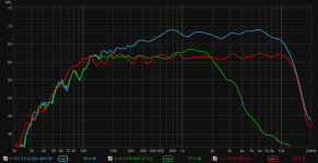
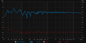
In the first attachment, you can see the blue midrange GP + farfield merged measurement I used to create the EQ. In green is a GP measurement I did with EQ, and in red is a 30" farfield measurement to confirm that both the merge operation and EQ are correct.
I can run through this procedure in 10 minutes if I’m lucky, or an hour plus if I interpreted the merge wrong and have to rethink it or measure again. I consider this result just about perfect, and didn’t have to model or account for the baffle step at all.
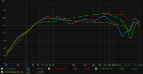
Here's my problem: this process does not work for my stacked woofers near the floor. Ground plane measurements suggest a baffle step, but using my process results in far field verification measurements with a downward sloping response, with the mic at any height or any distance. In fact, the only way to get a good final response is to assume there is no baffle step at all.
In the second attachment, you can see woofers on the design axis in blue, the mic at the same distance but woofer level in red, and GP in green. Notice the dashed yellow nearfield measurement seems to be a mirror image of the groundplane for most of the passband. I know the (too small) box alignment is not canceling out the baffle step, but leveling the GP measurement is going to do bad things to the other traces.
I don't know what I should try next.
- I use REW and variable smoothing 95% of the time. Sometimes I will use 1/24 to make sure I am not missing something important, and then I switch back to variable so I can work with the important trends.
- Take ground plane measurements at different distances. You want to be close enough to see a nice straight response without excessive smoothing, but far enough away that directivity does not kill the top end. If you are too close or too far away, you will see the response curve or ripple too much to be useful. I find 4ft to be a good starting place.
- Take far field measurements on the design axis at different distances. I like to start at 2x baffle width and increase the distance until ripples compromise the measurement above the point I think I want to merge to the ground plane.
- Overlay and align the two raw measurements' SPL, and make sure their IR peaks are aligned.
- Merge (with blending) just before the GP peaks and drops away (which is right at the point the farfield ripples get confusing) = ~700Hz for my 10” wide baffle
- EQ (IIR) the response down to flat (in REW) as far as practical to either side of the intended crossover frequency.
- Take a far field measurement to confirm the measurement matches the predicted EQ response. Start at 2x baffle width and go back as far as you can before you lose site of the trend (measuring outside, I stop at 6ft). The response should stay flat and not curve in the middle of the passband.
In the first attachment, you can see the blue midrange GP + farfield merged measurement I used to create the EQ. In green is a GP measurement I did with EQ, and in red is a 30" farfield measurement to confirm that both the merge operation and EQ are correct.
I can run through this procedure in 10 minutes if I’m lucky, or an hour plus if I interpreted the merge wrong and have to rethink it or measure again. I consider this result just about perfect, and didn’t have to model or account for the baffle step at all.
Here's my problem: this process does not work for my stacked woofers near the floor. Ground plane measurements suggest a baffle step, but using my process results in far field verification measurements with a downward sloping response, with the mic at any height or any distance. In fact, the only way to get a good final response is to assume there is no baffle step at all.
In the second attachment, you can see woofers on the design axis in blue, the mic at the same distance but woofer level in red, and GP in green. Notice the dashed yellow nearfield measurement seems to be a mirror image of the groundplane for most of the passband. I know the (too small) box alignment is not canceling out the baffle step, but leveling the GP measurement is going to do bad things to the other traces.
I don't know what I should try next.
Attachments
I am still trying to make sense of measuring woofers, and here is an idea; please post your thoughts:
- At high frequencies, a woofer has 2pi radiation just like a mid.
- Below the baffle step, it transitions into 4pi, also like a mid.
- However, the woofer will also transition back into 2pi at a point defined by its proximity to the floor.
- If the distance between the woofer and the floor is greater than the width of the baffle, then you will end up with a U-shaped response. This could explain my far field measurements.
- If the distance between the woofer and the floor is the same as the width of the baffle, then the two will cancel each other out and the measured response will remain level.
I saw your initial post, but as I have never carried out a ground plane measurement so stayed away.
The truth is in the data somewhere assuming the equipment is good.
Does your 10 inch baffle indicate why you have a peak at 700Hz.
What is your design, can you share dimensions and drivers for others to try and understand little bit more?
Merging nearfield and semi anechoic is as near as most of us can get. Maybe housing companies should build more homes with built in anechoic chambers at a rate of 1 per 10,000 houses approx.
However, the woofer will also transition back into 2pi at a point defined by its proximity to the floor.
- If the distance between the woofer and the floor is greater than the width of the baffle, then you will end up with a U-shaped response. This could explain my far field measurements.
- If the distance between the woofer and the floor is the same as the width of the baffle, then the two will cancel each other out and the measured response will remain level.
At least as for my midrange measurements:
The design is a TMWW with FIR LR2 crossovers at 2.5kHz and 300Hz, augmented with a sub via IIR LR4 at 80Hz. I keep meaning to post a complete design thread, except I spend all my time tweaking or enjoying them.
- Edge predicts a diffraction peak just above BSD, and my own measurements show something similar, although the measured transition point is at least 100Hz higher than predicted.
- My ground plane measurements remove all the ripples through the entire baffle step. I assume this is because floor bounce is eliminated.
The design is a TMWW with FIR LR2 crossovers at 2.5kHz and 300Hz, augmented with a sub via IIR LR4 at 80Hz. I keep meaning to post a complete design thread, except I spend all my time tweaking or enjoying them.
Attachments
Did you model the enclosure tapering shape and edge round overs using edge software?
If you apply a baffle step shelving filter 4-6dBs between 300 - 800 to the midrange so the midrange hopefully measures flat and then re measure what do the new results look like and do they provide a better understanding of what is occurring with the ground plane measurements?
Do some people carry out ground plane measurements with the speaker laying on its side, then all drivers are as near as possible to the plane.
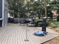
The image shows a conventional setup what does the response look like with corrections applied once windowed to show a 300 - 20Khz response
If you apply a baffle step shelving filter 4-6dBs between 300 - 800 to the midrange so the midrange hopefully measures flat and then re measure what do the new results look like and do they provide a better understanding of what is occurring with the ground plane measurements?
Do some people carry out ground plane measurements with the speaker laying on its side, then all drivers are as near as possible to the plane.
The image shows a conventional setup what does the response look like with corrections applied once windowed to show a 300 - 20Khz response
MtBiker, cool stuff...glad to see others trying outdoor (aka more anechoic) measurements.
I make them alot...here's what I do without claiming they are best way.
First, I toss the whole idea of baffle step. It's like who cares what it is when I have active processing.
I use a mic distance that reflects listening distance, but never less than 3X the speaker's greatest dimension, which gets me out of nearfield.
I avoid near field measurements and stitching together responses at all costs....
I put the mic on the ground, with the tip barely above the ground at some small angle. Then I find some way to tilt the speaker so that a line perpendicular from the speaker aims at the mic.
It's always a judgement call where to have the perpendicular line originate from, I usually use a point between the mid and HF drivers.
Mic on the ground is the biggie in all this, along with at least getting out of the near field. (where spl doesn't fall at 6dB per distance doubling, and summation is suspect.)
btw, the best way to mimic anechoic indoors that i've learned, is to lay a speaker on its side on the floor, tilt it and aim it at the mic on the floor in the same way as already described.
Holds up remarkably well to outdoors, considering reflections. (Oh, and toss any gating too.)
just my 2 cent way") i know many will say i'm crazy regarding baffle step, near field stitching, and gating ....but i also know the results i get
i know many will say i'm crazy regarding baffle step, near field stitching, and gating ....but i also know the results i get
I make them alot...here's what I do without claiming they are best way.
First, I toss the whole idea of baffle step. It's like who cares what it is when I have active processing.
I use a mic distance that reflects listening distance, but never less than 3X the speaker's greatest dimension, which gets me out of nearfield.
I avoid near field measurements and stitching together responses at all costs....
I put the mic on the ground, with the tip barely above the ground at some small angle. Then I find some way to tilt the speaker so that a line perpendicular from the speaker aims at the mic.
It's always a judgement call where to have the perpendicular line originate from, I usually use a point between the mid and HF drivers.
Mic on the ground is the biggie in all this, along with at least getting out of the near field. (where spl doesn't fall at 6dB per distance doubling, and summation is suspect.)
btw, the best way to mimic anechoic indoors that i've learned, is to lay a speaker on its side on the floor, tilt it and aim it at the mic on the floor in the same way as already described.
Holds up remarkably well to outdoors, considering reflections. (Oh, and toss any gating too.)
just my 2 cent way
i know many will say i'm crazy regarding baffle step, near field stitching, and gating ....but i also know the results i get I'd call them predominately home use, but with full PA capability and occasional PA use.
Hi-fi PA, I like to think.
Tis the sound that weaned me off electrostats...
Big thing for me with measurements, is how to measure and tune a DIY speaker as near anechoic as possible before putting it in a room.
I believe in doing this either way, whether strictly for home, or entirely for PA.
I believe it's a necessary step to be able to get the most out of any design.
Because once a speaker's measurements get commingled with a room, i've found it near impossible to separate fixable minimum phase anomalies from room relections and reverb.
It's really the same reason I always advocate measuring and tuning driver by driver first, before summing with xover. Once summed, no more min phase, and who knows what is legit to fix then....
Once the near anechoic tuning is done, I feel far more confident indoors with acoustic treatments and mode killing EQs, etc.
Knowing any other adjustments must be carefully considered, and may not even be helpful.
Last edited:
With your mic elevated from the ground plane, every measurement includes the "floor bounce" cancellation, which varies with measurement distance and mic height.Second, I acknowledge floor bounce is a major issue taking measurements, but I do not want to eliminate floor reinforcement from the equation.
All Mark's suggestions in post #7 (and #9) are correct.
Art
Last edited:
I do not see the problem. Ground plane measurement method is 2π (given no absorption) and has a bonus: it is 2π (almost) full bandwidth, just like a real free field measurement (no boundaries) is 4π full bandwidth. There is no 'baffle step effect' on behalf of the ground plane, because the microphone is ín that plane. Given the ground plane is sufficiently large of course, a few square feet and some won't do. But with appropriate gating even that aspect is manageable, with LF resolution as a sacrifice.
Laying the speaker on it's side eases off-axis measurements in the vertical plane, but you'll also need to appraise the horizontal plane. A turntable with a tilting option helps speeding up measurements.
No news this all though. I even have seen people suspend their DUT some six feet above the ground plane mike. Given a high ceiling and ditto lifting construction that can work out just perfect too.
With your mic elevated from the ground plane, every measurement includes the "floor bounce" cancellation, which varies with measurement distance and mic height.
Art
What I meant was that I did not want to loft my speakers way into the air in order to move the floor bounce out of the woofer's pass-band. If I did that, then I would also remove the floor boundary reinforcement that is part of the woofers' intrinsic response.
Did you model the enclosure tapering shape and edge round overs using edge software?
Edge let me do a taper, but not account for the roundovers or sculpting of the baffle. I have tried a few other applications and they produced similar responses, so I did not save them. I just wanted to have a guide for interpreting measurements in REW. If I narrow the simulated baffle quite a bit, then produces a response that starts to look like my GP measurements.
If you apply a baffle step shelving filter 4-6dBs between 300 - 800 to the midrange so the midrange hopefully measures flat and then re measure what do the new results look like and do they provide a better understanding of what is occurring with the ground plane measurements?
Look at the first attachment in my first post. The red trace is after applying EQ to the midrange baffle step and then measuring in the farfield to confirm.
Because once a speaker's measurements get commingled with a room, i've found it near impossible to separate fixable minimum phase anomalies from room relections and reverb.
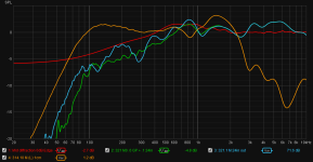
I have followed the advice at the end of this tutorial in using excess group delay as a guide for where NOT to EQ room response in the modal region. See the screenshot with the colored vertical bars.
I can lay a speaker on its side to measure indoors tonight, but will not be able to get them outside for several days.
BTW here is a measurement at 22" in the TV room with only 1/24oct smoothing. It measures exactly the same outdoors at greater distances, just without all the distracting ripples and nulls from reflections.
This is just the tower, but when crossed to the sub, I add room EQ below 100Hz and level the bass response at the listening position to flat. The room response >100Hz looks terrible, but I don't EQ that and it sounds fine.
This is just the tower, but when crossed to the sub, I add room EQ below 100Hz and level the bass response at the listening position to flat. The room response >100Hz looks terrible, but I don't EQ that and it sounds fine.
Attachments
I have followed the advice at the end of this tutorial in using excess group delay as a guide for where NOT to EQ room response in the modal region. See the screenshot with the colored vertical bars.
I can lay a speaker on its side to measure indoors tonight, but will not be able to get them outside for several days.
Yep, tutorials like that can really help. They are just way too complicated and fraught with a high probability of making errors imo/ime.
I'll take a good quasi anechoic meas over all that any day
Also, even with all the averaging, modes and reflections still become part of the final measurement we wish to correct.
So group delay analysis will show areas to leave alone, areas being masked.
Whereas, there may be some real min phase work to do in those areas, if not for the masking...work which will only be seen quasi anechoic.
What does it do if you lay speaker on it´s back and measure it up to the sky?
It's an ok technique, but the bounce from ground will be strong in the measurement.
Folks have built sand pits to lay the speaker in, and then grade flush with speaker.
Super technique...if i still had my farm i would probably do it if i could figure out drainage....
I do not understand the benefit of measuring a speaker buried in the ground. Yes, it would remove reflections, but it would yield a 2pi measurement at all frequencies which is not representative of what radiates into the room. Like a nearfield, it might show you something useful (like bass alignment), but I don't really see how it would be usable.
- Status
- This old topic is closed. If you want to reopen this topic, contact a moderator using the "Report Post" button.
- Home
- Loudspeakers
- Multi-Way
- Ground plane measurements results (good and bad)