Cheap Chinese 24 position attenuator

OK, I didn't have $250 for a gold point stereo 24 position 100K attenuator. So, I bought a couple of cheap Chinese ones off of ebay, see attached photos. I know, I know, let the moans and groans begin. Anyway, I spent about an hour with my DMM and for the life of me can't find the terminal that correspond to in, out and ground. Anyone have experience with these? Thanks in advance for you help.


In
|
>
>
><---- Out
>
|
Ground

Attachments

  • IMG_3259[1].jpg
    IMG_3259[1].jpg
    436.9 KB · Views: 175
  • IMG_3260[1].JPG
    IMG_3260[1].JPG
    927.8 KB · Views: 177
  • IMG_3258[1].jpg
    IMG_3258[1].jpg
    523.1 KB · Views: 167

Castle Microtower build

Micro Towers - I can't exactly remember which one I came across first - the plans on Planet 10 website http://homepage.mac.com/tlinespeakers/FAL/downloads/microTower-maps-150909.pdf, or this thread by Dave: http://www.diyaudio.com/forums/full-range/148901-microtower-bipolar-ml-tl-chr-70-el70-2.html. Either way, I loved the intro... a bit of nostalgia, a bit of reviving a joy of the past... and the build looked simple, the finished speakers cute. Compact dimesions = (usually) Higher WAF 🙂, especially given that my first FR build was the BIB (pretty massive); then the plan was to build a Pensil 12 which became a Super Pensil 12 (pretty massive too).

I was also looking for speakers which could produce good bass and became very excited about FAST. After discussing FAST with Dave I had initially planned to order a pair of Alp 7 or CHR70.2En from Dave as FAST FR units. Dave's CHR70.2Ens were on sale at that time, so just decided to pick up 2 pairs... a pair for FAST and a pair for other experiments.

And then it hit me - why don't I do a Micro Tower build? According to Dave and ChrisB the MTs give plenty of bass... also the MT dimensions looked a perfect fit to me for using my left over pieces of ply board.

And so it was decided - let's go and build this! The picture below is not my buidl, but a concept build by Dave and Chrisb taken from the plans. If you take look at the illustration (taken from P10 plans), you will see how compact the speakers are (and the variations that can be made).

-Zia

Attachments

  • P10 MT concept build.jpg
    P10 MT concept build.jpg
    60.6 KB · Views: 1,554
  • P10 MT illustration.jpg
    P10 MT illustration.jpg
    71.1 KB · Views: 1,171

When does something qualify as a front chamber?

I found some Adire Audio 12" Brahmas in excellent condition that somebody was selling on Craigslist for $125 for the pair. I bought them not really knowing too much, but after some research it appears that these are quite legendary. Very capable SPL and SQ, so I am excited at the prospect of being able to build some high-end subs. I am looking to build a ported enclosure with one of them for use in the home. Problem...I have very limited floor space and a wife who understandably does not want any more taken up.

I was looking into building an enclosure beneath my house. I have seen bandpass designs where just the port fires into the room, and I guess I could go that route. But I was really hoping to build a vented system. My question is, if I build a ported enclosure and both the woofer and port fired into a "chamber" that goes to the room, then is this just a bandpass? For instance let's assume the front baffle of the enclosure is 18x14 and fires into a "chamber" that is 18x14x6 such that the 14x6 dimension is a hole in my floor covered with a vent to make it look like a heating vent.

I am thinking all speakers fire into a "front enclosure" that is your room, but at some point that enclosure is so large that it does not affect design. But I don't know how large that area needs to be. It made me think of car audio...is a sealed sub in a car with a window partially rolled down now considered a bandpass enclosure to those outside the car?

Thanks

Filtering the ground line

I get a nasty (high freq) buzz on the ground line. When I lift the ground connection, the system is quiet. This is on my pre amp. However any other source component that is grounded immediately introduces this buzz again -- as soon as I plug it in.

Also, this nasty buzz usually instantaneously goes away later at night, around midnight. Nothing in my house, as far as I can tell.

So can I install some type of a ground line filter? Is there such a thing? Recommendations?

thanks.
Herman

soldering a TO-3 transistor technique ? (problem for me)

haha, i'm currently soldering some circuit and it involve a TO-3 package transistor (MJ15003).
Well.... this is the second time i try to solder such package, but both are difficult, as they are hard to wet with my solder (its my solder problem ?) They cannot 'bond' to the surface of it, which easily came off if use a small force (shaking also will do).

The problem of base and emitter terminal are not so much problem (as pad let us do easy job, but they still hard to solder than typical TO-264 or similar (which standing, not flydisk shape)
The collector (entire casing and 2 holes) surface is the most difficult, like spending most of the time doing that and FAIL !

So any guys have nice and brilliant idea or experience to share with me ? in order faster and easier to solder these TOUGH 'guy'.

v.divider+v.follower or v.regulator

hello. i have a question about pairing voltage with application.
i have a source of 12V and i need to work with a fuzz face pedal distorsion with germanium transtistors and the the pedal should get 9v.
what is the best solution for this?
i thought about a voltage regulator or a voltage divider + opamp as voltage follower.
the best solution would be the voltage divider but i'm considering a walkaround. any pro/cons?cheers

Attachments

  • Germanium-Fuzz-Face-Schematic.jpg
    Germanium-Fuzz-Face-Schematic.jpg
    263.7 KB · Views: 111

d&b audiotechnik Anyone knows which driver brand they use?

Hi,

I would like to know if any on you you know which component brand does d&b audiotechnik use in their systems, particularly:

-. the 12" neodymiun woofer in their J12 system; and
-. the 1.3" exit HF compression drivers with titanium diaphragm in their C3 system.

Sorry i post this here, but I know there are many users from europe in this forum.

thank you in advance.

Sowter 9335 as input - hard noise when switching

My recent build is a SRPP pre-amp which has too much gain for me so I will probably rebuild it into something like this Muchedumbre Buffer Preamp – wauwatosa tube factory

But I think with two halves of the 6sn7 I am using in the SRPP

Now my question is as follows:
- I use Sowter 9335 as volume control
- Switching is by relays kit from Dantimax, this works fine
- However there is a lot of hard noise while switching, really annoying. Is this because of the high gain? Or because of the relays?
- Also do I still need a grid resistor after the Sowter?

BHSE cannot adjust bias

For my BHSE, I have changed the original Mullard EL34 tubes to another brand. But the sound of my left side became a bit, how should I say, veiled. The higher the volume and the higher the pitch, the more obvious, like playing songs by soprano.

This still happens after I have changed back to the original Mullard tubes. Has anyone experienced this before or know the reason?

I have discovered that the bias the bottom left tube (left offset) cannot be adjusted. Has anyone experienced this before? Or does anyone know how to fix the problem?

Thanks a lot

Carvin SX-15 Preamp

Hi everybody,
I am attempting to build a bass amp head utilizing a Carvin SX-15 Preamp and a DBX 1 Compressor/Limiter 262. I am looking at a 210 watt per channel (420 watt Bridged) power amp board. Typical bridged configurations only use one of the input channels. I want to retain use of both channels while in mono but I am concerned about combining right and left outputs from the SX-15 using a common ground. Will this damage the preamp? I would also like to maintain the versatility of switching between stereo and mono. Anybody have any input?

Single rail 36V about 200W power supply for TPA or TAS3251 amp

Hello,


I have designed a class D amplifier board based on a TAS3251 chip (TPA3251 + DAC+ DSP in the same chip).


I now need to buy the power supply. My initial intention is to go to a Meanwell LRS-350-36 (MEAN WELL LRS-350-36 Switching Power Supply SMPS 36V 9.7A 350W - Audiophonics). I have read several good recommendations for those.


However, I'm a bit bothered by the fact that those power supplies are not optimized for Audio. They can deliver a steady 350W, while I will normally have much lower needs, but need a to be able to cope with short peaks. TI has some suitable reference designs with 200W nominal and 600W peak (from memory).


I understand that DIY is not easy in that area because of specific transformers and coils (and voltage). Drmord proposed an interesting desgin, but from the Google translate of the article (Russian), making the transformer looks like art :-(


CONNEX modules are more significantly more expensive that Meanwell. Hypex even much more.


At the bottopm end of the cost spectrum, some cheap modules like Nouveau Module d'alimentation 36V 5A AC DC Module d'alimentation a decoupage carte ca 100V 240V a DC 36V alimentation a decoupage|Alimentation a decoupage| - AliExpress


What are they worth ?


Other interesting products to consider ?


And to increase my knowledge: what should I look at for those type of power supplies. What are the interesting features / performances ? What to stay away from ?


Help welcomed,


JMF

SB Acoustics SB12MNRX25-4 as a fullrange

Has anyone tried to run this driver fullrange ?
It looks fairly flat up to 10 khz on manufacturer`s graphs , with -5 db drop up to 16 khz . I was thinking about running it fullrange with aid from my amp's treble knob that starts regulating from 10 khz so this would be ideal , or maybe with help of a tweeter playing from 10-11 khz with only a cap and resistor in series.
How would it stack against the specialised fullranges ?

Help sourcing a inductors summing amp

HI Guys,
I have a question regarding a summing amp that I am about to build.
I am posting the schematics and a picture of the original card.
could you help me sourcing this inductors and from what type it is exactly ?
We talk about L9 and L10 here.
the value is 15 uH.
thanks a lot !! 🙂🙂🙂

P

Attachments

  • 15uH PICT 3.jpg
    15uH PICT 3.jpg
    80.5 KB · Views: 120
  • SHEM.png
    SHEM.png
    253.1 KB · Views: 123

newbie DIY PA open baffle + H cab sub?

I am putting together a PA system for piano-organ-voice and harmonica playing usually in a relatively small practice space. I don't need huge volume potential but want to get a full and natural sound.
I have done lots of projects and built electric and acoustic guitars, but the only experience I have building audio speakers is years ago when I put a pair of vintage Western Electric 755a speakers in and open baffle. I loved the simplicity of that form and want to create something similar at a larger scale for practice and performance.
I am using some new parts and some items I have been using with my current setup... re-used will be a Mackie 8 channel mixer for input. New is a B-52 Matrix-1500 BBE 3-Ch Plate Amplifier (1200W w/sub crossover), two Eminence Beta-12CX 12" Coaxial Driver with PRV Audio D280Ti-S 1" Titanium Horn Drivers and LaVoce SAF184.01 18" Subwoofer.
I'm thinking of putting the 12's in an open baffle and the sub in an open "H" cab.
is that a stupid idea? and how much math do I need to learn to figure out the dimensions of the baffle and sub cab?

Amp Howls

I have a subwoofer amp I built from an Electronics Now (remember that?) magazine article around 1992 or so. Recently it started making whoosh/thunder noises, now it just howls. I have the schematic and can trace down the parts, but was wondering if I should focus on a bad cap or something or do I have to check everything (IF I want to keep it)? Thanks for any help.

Help with finding new drivers for existing enclosures

Hello people of diyaudio.

I am looking to reuse an old set of fairly well build enclosures for a new project. The enclosures have cutouts for two 10" drivers on the front panel and a removable rear panel, as shown in the attached picture.

I currently don't have the capability to make new enclosures from scratch, but i should be able to build new rear panels plus what other small changes/fixes would be needed.

The enclosures have an internal volume of about 95 liters, but i would like to use a pair of hypex fusion plate amps so i expect the volume to be closer to 85-90 liters with their box included.

I have already tried modeling the enclosure in bassbox 6 pro with a single peerles XXLS-P835016 per box and a bending bassreflex tube of 100mm radius by 452mm length that's flared in both ends. This seems to be an ok option with an F3 of under 24hz, though i am unsure if a peak vent air velocity of 18.4m/s is ok.

My goal is to get a frequency response from around 20hz to 200-300hz. I hope you guys can help me with ideas for drives suited for this enclosure 🙂

Attachments

  • subwooferbox.jpg
    subwooferbox.jpg
    743.3 KB · Views: 134

How to remove lettering from chassis

Hi there, I bought a chassis with some lettering on the front panel I would like remove so its generic. I have tried Isopropyl and nail polish remover with no success.

I thought I saw a thread on this but can't seem to find it now. I know there is one on how to put lettering on a chassis but I want to get rid of a manufactureres name on mine.

Thx in advance
Neville

Is this a new topology?

attachment.php


By giving a hand to zintolo with his GU50 projects I came upon this circuit. The bootstrapped pentodes provide a gain of 75db ,yielding 40 ohms plate to plate output impedance for 6k load by plate to cathode feedback. The input inverter comes from Audio Research D70 , It can function without by parafeed mode but oscillates on saturation. Using Ayumi models the amp exhibits 80w with 0.03% Dtot.

Attachments

  • GU50 SCAHET.JPG
    GU50 SCAHET.JPG
    214 KB · Views: 1,550

Audio Note UK Model Soro SE Integrated - audio playback distorted

Hi,

I have an issue with my Audio Note UK Model Soro SE Integrated recently.

My Soro SE is the model with ECC82, 6SL7 and 6L6/5881 tube.

The audio playback will begin to be distorted, especially obvious with mid range like vocal after power up for around 35 mins to 40 mins. The duration the audio playback begins to distort is always similar each time. This problem seemed to be related to heat, maybe some component is not working properly when heats built up.

if you have a similar experience and can advice what is the likely cause of this issue. Do also share with me if you have the schematic of this amp.

Thanks.

Toroidal PowerSupply Pre-Amplifier

I need help to fix my Plinius M8. Specifically its Toroidal Transformer Power supply. Attached here are the pictures of the unit and the drawing. I was hoping if anyone could give me a data sheet or complete specifications of the power supply which is the Toroidal Transformer of the Plinius M8.

Attachments

  • 20200513_125511.jpg
    20200513_125511.jpg
    934.3 KB · Views: 185
  • 20200513_140515.jpg
    20200513_140515.jpg
    333 KB · Views: 174
  • 20200513_132008.jpg
    20200513_132008.jpg
    776.8 KB · Views: 174
  • 20200513_130217.jpg
    20200513_130217.jpg
    878.4 KB · Views: 172

Carbon film resistors in crossovers

Hello, 🙂

I'm planning to attenuate the tweeters in my speakers.

With my new amp, the upper midgrange and the top end can be a little bit on the cold side on some recordings.


I was planning to use metal oxide resistors, but I got some advices that I could try carbon film instead.

It turned out that some manufacturers are using bunches of 10 or more carbon film resistors connected in parallel:

r_9.jpg


x_12.jpg


Upon further reading, I found claims that metal oxide resistors are technically "better" and more precise, but that they can be cold sounding.
Carbon films are technically inferior, but they are warmer, more musical, etc:

Carbon Film vs Metal Film revisited


So guys, do you have some/any experiences with carbon film resistors in speaker crossovers?!

In my country, the choice of high quality components is very limited.
These are the carbon film resistors that I can buy at this moment:
Cinetech Ind. Co., Ltd
http://www.cinetech.com.tw/upload/2011/03/20110330164634.pdf

What do you think?

Thanks in advance,

Aleksandar 🙂

Small stereo amp for tablet/smatphones

This is my small, minimal and very simple stereo amp for tablets/smatphones.


All components, eccept tubes (NOS), are recycled from old non-recoverable radios (resurrection from the grave)
The chassis is from an old Phonola radio from the early 1950s, upside down from what it was originally to obtain a support surface for the smartphone
The two little lamps (2x6V in series) on the side, are used to light up the smartphone (at night)
The big filter CAP was put close to the output transformer because I needed to cover a big hole
I choosed 12AT7/ECC81 and 6AK6 because their very low heaters current (power saving), you might try to use ECC82, 12FQ7, ECC83 at place of 12AT7 (same pinout), and use 6G6G (same tube different pinout) at place of 6AK6
For smartphone recharging I used a cheap 12V to 5V car audio USB power supply

NOT SUITABLE FOR CHILDER USE, SHOCK HAZARD!

Note: I am planning to add a small Bluetooth module (recycled) to this amplifier.


RecycleReduceReuse.jpg


Output Power 1+1 W
Output audio transformers: 10K SE (EL95/ELL80)
Tubes; 12AT7/ECC81 - 6AK6(=6G6G octal)
Total heathers current: 0.3A @ 12V
note: 6AK6 heaters in series (6+6V)

Main voltage: 110/120 Vac (about 135-150Vcc after filter cap)
Output: 5Vcc 1A for device recharging

20200512.jpg

6ak6am10.jpg

balancing in an unbalanced world - help

As I await my delivery of a bare board pre from Tortuga (single ended unbalanced LDR) I will be encasing it ans wiring it up to input and out sockets. I would rather not use RCA phono, because I am feeding the pre with a DAC that has balanced out XLR, and a phono set from my turntable phono amp. The pre then outputs to a DBX Venu360 (also XLR) to do digital crossover into two sets of power amps to drive a pair of hybrid ESLs.

I also like XLR plugs from an engineering standpoint and have all the necessary balanced quad core cables, so don’t really want to rip them apart to make a balanced to RCA cable.

So my plan is to wire the XLR sockets and plugs in the amp to treat them as single ended.

There are many views on how best to achieve a balanced out to unbalanced in and unbalanced out to balanced in. My research based on this site Dealing with unbalanced gear in the studio - Crookwood leads me to the following plan, though I have to confess the more I think about, this more confused I get. Especially as what I am doing is a little different, in that I am trying to preserve standard XLR cables and get the right result by correctly wiring up internally. The DAC is a Chord Hugo TT, metal chassis with wallwart DC power (not sure if that makes it a floating or mains earth, I am guessing floating) The DBX is a pro unit with earthed mains in, so I am assuming this is a mains earthed unit. It also has a pin lift that can help with earth loops)

Please let me know if you agree or have a better suggestion.

For the input from the balance cables from the DAC

Internally within the amp, wire the hot pin 2 to the board, connect pin 1 and 3 together and earth on the chassis, or should the earth be taken from pin 1 and 3? The earth to be chassis earthed in a star.

For the output from the pre to my DBX, wire the signal +ve out to pin 2 again, and again connect pin 1 and 3, wire this to the -ve output signal.

Any help would be gratefully received

Class d amps, based on this design troubleshooting

Hello, I have three amps, based on this design. What are the common drive board problems? Output fets are irf9640 and irf640n. I have high and low side drive, fets get hot quickly. On another amp, there is jo drive. Checked all parts, changed lm393, drive OK. Fets get hot. What is the right part number for the drive transistors AG and dk?

Attachments

  • IMG_20200515_094757.jpg
    IMG_20200515_094757.jpg
    993.4 KB · Views: 140
  • IMG_20200515_094807.jpg
    IMG_20200515_094807.jpg
    378.7 KB · Views: 127
  • IMG_20200515_094822.jpg
    IMG_20200515_094822.jpg
    278.8 KB · Views: 116

FS: MC35084/MC33284/AD536 etc

Came across a stock of new, unused parts from my early designing days, all from US sources. If interested, send me an offer:

MC35084L Mil Temp Quad Op Amp -- qty 40
MC33282 Quad Op Amp -- qty 20
MC33282 Dual Op Amp -- qty 20
AD536AKD/AJD RMS to DC converter in CERDIP -- qty 8
Intersil / Harris / Maxim -- qty 20
OP97F -- qty 20

I also have some values (40 ohms, 301 ohms, 1K, 5.69k, 825 ohms and some others to be catalogued) of 1/4W PRP 0.1 to 0.01% TC25 resistors from the early 2000s. Practically hundreds of each value.

I will continue to add as I find more. Again, if interested, please PM.

Basic Questions on input to AMR DP-777 SE DAC

Got a question for all you Digital folks!! I don't much dabble on this end, as it has mostly been set Digital DAC up and forget it if it sounds good (and it does).

I have an AMR DP-777 SE DAC connected to my computer (spdif off mobo).

I have the following option for DAC inputs:

Option 1: 2 x AES XLR / BNC

Option 2: 2x Toslink / COAX (RCA

Option 3 1x USB Asynchronous

All the above go thru a 6922 (or a 5670 with adapter) Tube stage after DAC and out to the preamp.

Now Option 1 is the extra special HD Digital input that goes thru another tube (6H11), and is supposed to be the recommended connection. I currently have this connected via a cable I made - BNC/COAX terminated with an RCA to computer.

Here is the issue... my computer is around 15 feet away from my DAC, and using Toslink, COAX (RCA) and BNC cable I have issues locking at rates over 48khz...cannot lock on 88khz, 96khz, and 196khz. Currently set at 48khz with no issues.

And yes, I know I could move computer CLOSER to DAC... and would rather not just purchase a $300 special magical cable to 'try"... just trying to look at the obvious things first...

Now my questions:

* I have another computer I am considering making the SOLE music source - like the one now, I get all spdif off mobo...maybe swapping computers may have stronger signal drive so I can get over 48khz to DAC?

* Async USB input may get me the higher rates (only one that does 196khz methinks), but has a cable length maximum of 5 meters - around 15 feet, correct? And the USB input does not go thru the magic 6H11 tube like inputs on option 1

* I have a sound EMU 404 sound card I can throw in my computer that may have the additional Signal drive to get that higher rate signal to the DAC...could this help?

* I am using Chrome (Pandora on hi rez) and iTunes - nothing here would matter on getting higher rates to DAC, right? Current rates set on Windows...

* Is 48khz sampling good enough? Am I kidding myself thinking computer output at higher rates would make a world of difference? I do have a couple higher rate downloaded media...

* I can get 48khz input, and upsample to 88khz or 96khz (or 196khz maybe) - theoretically, worth it and better than straight 48khz? Same input rate signal tho...never quite understood how upsampling would make a difference...

Appreciate the help!! Go easy on me, please!!

Replacing cabinets

Hi all
This is my first post and I’m new to diy hifi(always just bought it😂)
I’ve got some Rogers ls55 speakers that I like a lot but are looking tatty and they seem to be quite poorly built chipboard so I was thinking of having some new cabinets made (I’ve emailed wilmslow audio)
Or I could build some myself what’s the best route to take what material to use etc will it improve the sound etc or should I just buy new speakers🤣😂🤣😂
Any help would be great fully appreciated
Cheers
Scott
Ps my dad loves a bit of woodwork and has a garage full of tools table saw etc

Floor noise tpa3116 with wired pots out board

Hello guys!
I have a problem with tpa3116d2 board and I need some help.
I recently made a boombox speaker with the look of retro marshall models, the problem is that when I separate the potentiometers from the board and mount it them with 10cm of cable, the speaker has background noise as if the cables were antennas, when i put my hand near of the potentiometers also increases noise... and more if i touch them. Is there anything i can do to fix it? I put an aluminum shield over the wires each potenciometer and put it to gnd and results are better but the noise is audible yet.
Thank you very much for your responses.

speaker picture: Shared album - Diego Riveiro - Google Photos
Shared album - Diego Riveiro - Google Photos

120V AC to 12V DC w/ Tube Rectifier

Hi all,

I'm a NEWB - so apologies for my ignorance in advance - I'm just starting out.

I'm looking to build a DAC with a tube rectified power supply. The DAC board I'm considering needs 7-9V AC or 12V DC (see here) or this snippet on power input from the manual:

Power input 7-8V AC or +-7-15V DC max 5W

So my question is - how do I design a tube rectified power supply to deliver 12V DC? I found this tube rectified kit and they recommend the input transformer - I guess I'm just not clear on the output voltage of this unit and how to get that (presumably much higher) voltage down to 12V DC.

(Also, clearly, I'm not sure of a lot of things - but I'm trying haha!)

Cheap Chinese AK4490 boards

I have an AK4490 DAC board which I'm quite pleased with. I'm thinking of getting a second board where I can adjust the gain on the op-amp output. I've seen this one with leaded components which would make the task easier, however there is no information about what kind of USB input board is needed or how to connect it. I'm not too confident about getting such information out of the seller, and it would help if anyone here could advise me.

Upgraded Assembled AK4490 Chip EQ II2S DAC Decoder Board 32BIT 768K

Upgraded Assembled AK4490 Chip EQ II2S DAC Decoder Board 32BIT 768K | eBay

Attachments

  • AK4490-04 copy.jpg
    AK4490-04 copy.jpg
    115.4 KB · Views: 253

KMA-100MKII to KSA-50MKII rebuild - Sanity check requested

I recently bought a non-working Krell KMA-100 MKII for $180. The main fuse breaks when powered on. Since I'm unlikely to find (or afford) a second unit, I'm researching whether converting it to a KSA-50MKII is reasonable. I'd like to use the chassis, transformer, large filter caps, heat sink assembly, etc, but set aside the original driver and output boards, and replace them with entirely new PCBs and components. Some things I need to determine:

Power transformer: I read in another thread that a stereo to mono Krell conversion does not require a transformer swap. Assuming mono to stereo might also be possible, what would be the best way to configure the secondaries for two 50w stereo channels? Is there a way to supply each channel with 1/2 the original rail voltage?

50W or 100W: Given the PSU question above, if I need to live with the original KSA-100 rail voltage, can I still safely make this a KSA-50 re-build, or would there be a large amount of re-work to the KSA-50 circuit required?

If it helps with current/ heat issues, I'm ok with biasing the amp back to 10-20w of class A operation. My goal is just to retain as much of the original Krell sound as I can. Appreciate any advice on whether this might work or not.

Jason

Attachments

  • Krell_KMA100MKII_Front_diyaudio.jpg
    Krell_KMA100MKII_Front_diyaudio.jpg
    75.3 KB · Views: 737
  • Krell_KMA_100MKII_Inside_diyaudio.JPG
    Krell_KMA_100MKII_Inside_diyaudio.JPG
    116 KB · Views: 1,050

Complementary JLH10

As there seemed to be some interest in a complementary version of John Linsley Hood's 10W amplifier I've started this thread to see what pans out.
I've not built this, but it seems to behave in simulations and is stable in a Tian probe with 60 degree phase margin and 40dB gain margin similar to the original.
It's a bit watty in the driver stage, and needs 2W 100 ohm load resistors. The driver transistor also needs a good heatsink - or mounting on the output transistor heatsink as it dissipates 2W. It could probably manage 40V (up to 16W output 8 ohm load) as its second breakdown (as originally published by Mullard) is getting close. The standing current is estimated at 1.5A.
Distortion simulated at under 0.1% at 20kHz and 10W.

Attachments

  • JLH10CS.png
    JLH10CS.png
    8.9 KB · Views: 397

Coding Error in Zaph Audio measurement comparisons--how to fix...

I just thought I will post this here, since others may find this useful.

Although the driver comparison pages may be a bit old by now, many drivers Zaph compared are still available, so it's nice to have his detailed comparison data.

However, there is a problem in the Javascript code. Notice the "undefined" word under "previous... toggle... next". That is supposed to show the name of the driver and it's price.

Now when you just want to use these previous and next buttons (very convenient), you will get lost and have no idea which driver data is displayed, since it always says "undefined".

The reason for this is an error in the Javscript code, namely that `name` is used as the array variable name for driver descriptions.

If you want to fix this, it's fairly simple, even if you don't understand any code. Just download the page (Ctrl+S) and make sure it says "Web page, complete" when downloading. Find the downloaded page and open it in a plain text editor (e.g. Notepad on windows, Text on OSX). Look for the script, which is between the <script> and </script> tags. There is a long list of name variables, e.g.:
name[1] = "Audio Technology 18H520613SD ($525)";

The `name` is the problem. Now change all occurrences of `name` in the script to something else, e.g. `description`. These occur in the long list, just above it (var name = ...) and in the first function (setSlideNum). Save the changes and open the page you just modified in your browser, and now the proper description should show up.

This sounds more complicated than it is... trust me 🙂

I was going to tell Zaph about it, but there is no email link... I could post the fixed results on my server, but I would not want to do this without his permission. Unless Zaph chimes in, you will have download the page and fix the code yourself.


By the way: I don't have Internet Explorer, maybe his page works fine in that browser, it does not in Firefox or Chrome however.

Help! Blown Amplifier

I recently replaced my Nad c372 with BTE upgrade passive pre and a Quad QSP so I'd owned the Nad c372 for about a year and as a temporary fill in and it didn't ever display problems.

It was sold on eBay and the new buyer said that after listening to a couple of tracks
at normal levels it made a popping sound and smoke came out from the right side.

I now have it back and it won't power up at all I have removed the cover and though there is a smoke mark on the right side there is also a smaller mark on the left.

Now admittedly I don't know the inside of an amp from the back side of a donkey there are no obvious signs of burned or leaking components.

My question is it worth fixing or do I cut my losses and sell on as is.

Cosmetically it's in excellent condition.

Measuring power amp output impedance

How do I safely measure the output impedance of a valve amp? GM70 DHT in this case. The methods I have seen refer to SS amps, comparing infinite to known load, and that doesn't seem appropriate for a valve amp. I have sig gen, various voltmeters and a dual beam scope.
Would it work simply using two reasonable resistors (say 5 and 20 ohms) and calculating from there?

4-Way Open Baffle - Crossover question/need advise

Hi everyone!
I've started an 4 ways open baffle project with:
2 x Beyma SM118N on the bottom
1 x 18Sound 12ND610 8ohm

1 x 18Sound 6ND410 8ohm

1 x Satori TW29RN-B


Baffle is 140cm x 50cm


I'd like to go passive at least between 18Sound 12ND610 and 18Sound 6ND410 and to use them as wise as possible. Any suggestion for the best crossover points for the whole project is useful.


I measured them with DATS V2 and Omnimic but I am not sure about my Omnimic results and I don't understand yet how to use Xsim or any other software used for crossover purpose.


Can you please advise me with a passive crossover for these two drivers?
Attached is the .zma and .frd files for these two drivers.

Thank you!

Attachments

Screen Ratings

I'm getting a bit tied up understanding maximum screen ratings, especially when the max screen rating is a lot different to the maximum plate rating.

For example, the 807 has a plate limit of 600Vdc, and a screen limit of 300Vdc.

As far as I can understand it, it is not just a question of the voltage, but also the implied dissipation on the screen, since screen current is generally a proportion of the plate dissipation.

So that would imply that if voltage and current are known, then maybe screen voltages can be exceeded in some cases.

However, plate behaviour is also dictated by screen behaviour, so if a screen voltage is too high, then plate current can increase and exceed the plate dissipation limits, causing red-plating.

I have read this can be linked to the way the grid is wound, and in some cases it is hidden behind other grid windings, and in other cases it is not, and hence dictates the behaviour of the tube a bit more. I think an example of this is an EL86, which is sensitive to the screen voltage being exceeded.

All of this is static behaviour - the DC operating point. There are also the dynamic conditions, where a screen with a fixed supply can become positive to the plate, so could have large current changes.

Then in some cases people are using tubes with lower screen ratings in UL with, say, a zener diode string to clamp the maximum voltage. Isn't that going to need to be bypassed so that the dynamic behaviour is correct (if feedback via UL is the goal)?

On the 807 PPP UL thread the idea of a tertiary screen winding was bandied about, that is going to be prohibitively expensive for most people.


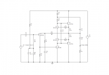
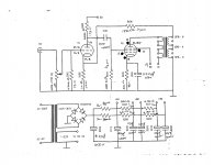
What I am trying to do is find a home for some 807 look-a-likes I purchased. They sit very nicely in a Quad II, with a B+ of 330V, and with a 390ohm cathode bias resistor, they have a quiescent current of 58ma. The tubes are operated as pentodes, and the screen supply is regulated from a choke, and is at 325V. The cathode is at 22.5V, so the screen is slightly exceeding its limit of 300V.

What do I need to do to be confident I am not abusing my output tubes? I'm thinking a screen resistor might be prudent to measure current? Or can I measure the resistance of the choke, and infer the current from the voltage drop?

As an aside, has anyone experimented with 5B/255M here?

Fostex FE103En vs. FE126NV - only 1/2" bigger, same VC, 3x power handling?

Hi,

I own the FE103En in a bookshelf speaker (the Fostex-branded horn ones), and received the FE126NV for use in the larger small floor-standing back horn kit.

The voice coils are the same diameter, only 1/2" size difference between them, but the larger driver is rated at 3x the power handling.

What attributes of the larger driver allow this? I know 3x the power is not 3x the sound, just asking about what allows it mechanically to handle that additional power. For one, I think the magnet structure is significantly larger. I don't see excursion parameters for both to compare.

Just curious!

Thanks!

Clicks and Pops

I recently struggled with a difficult click/pop issue with an external dac, and found a fix (in my case, it required replacing the laptop power supply).

I thought I'd share the results of my investigation here. Hopefully it may help others struggling with similar issues

DPC latency checker DPC Latency Checker
- Look for DPC latency spikes. If they coincide with glitches:
Latency Mon Resplendence Software - LatencyMon: suitability checker for real-time audio and other tasks
- Use it to find drivers that cause excess dpc latency and focus on fixing these: go to drivers tab, sort under highest execution (ms)
- List of common driver issues: https://www.sweetwater.com/sweetcare/articles/solving-dpc-latency-issues/

Fixed Windows 7 Sound (Popping, Cracking & Skipping) | Corey DeGrandchamp
- Playback devices-> choose dac-> properties-> enhancements tab->disable all sound effects
- if both the ethernet port and wireless were active at the same time, I would get multiple svchost.exe spikes and the system would skip. I use wireless at my house so I disabled the ethernet port, since then no problems.
- Disabling everything in Network Connections except for the Wi-fi adapter stopped the cracking right off.
- Disable nvidia geforce powerizer

Optimizing Windows for Audio – Ableton
- Update drivers
- Use large audio buffers
- Run->Msconfig->disable unnecessary start up programs
- If graphics problem, Torches utility of PC but: Run-> SystemPropertiesPerformance ->Visual Effects tab->Adjust for best performance
- Turn off internet disable Anti-Virus
- disable Bluetooth
- Power options: Control Panel -> System and Security -> Power Options-> High Performance
- Control Panel ->System and Security ->System -> Device Manager -> Right Click each USB Root Hub->Choose Properties -> Power Management-> Make sure "Allow the computer to turn off this device to save power " is unticked.
- Generally not recommended as it makes PC run hot and fan to spool up, but if cpu is bottleneck: Power Options -> Change Plan Setting -> Change Advanced Plan Setting -> Processor Power Management-> Set Minimum Processor State to 100%.

https://forum.watmm.com/topic/89732-awful-clicking-audio-on-pc/
- update bios
- update foobar
- turn off wifi and antivirus
- increase asio/wasapi process priority in foobar
- disable system sounds
- Try Wasapi event

https://www.cantabilesoftware.com/glitchfree/
- More drastic changes that will affect PC operation but may fix issue

Other
- Start > Settings > Control Panel > System > Advanced > Performance Settings > Advanced Tab > Adjust for best performance of Background Services
- Paul McGowan (PS Audio): connect the computer to the Dac through a USB hub, .. offers a degree of isolation between the computer and the DAC, though its not complete
- 3 prong ac brick for laptop may cause ground loops leading to issues. Replace with double insulated power brick

Other resources
https://support.audient.com/hc/en-us/articles/202335209-Optimising-Windows-Computers-For-Audio
https://www.soundonsound.com/techniques/eradicating-pc-audio-clicks-pops
https://www.soundonsound.com/techniques/optimising-latency-pc-audio-interface
https://support.native-instruments....1729-Windows-Tuning-Tips-for-Audio-Processing
https://www.cambridgeaudio.com/en/technology/usb-audio-optimizing-windows-directsound-wasapi-asio

Adjustable Directsound Buffer Size?

Howdie,
Is there a way to adjust system wide audio buffer size using DirectSound in Win10?

[System Audio]->EAPO (equalizer APO) ->USB asynch DAC

ASIO drivers support larger buffers that can avoid audio dropouts, but I'm hoping there's a way to do this (3rd party utility, generic USB audio driver?) when using directsound. It probably has to be USB driver based since the dropouts occur when the DAC buffer underflows.

Search on the web and here draws a blank, even on the question.

Thanks for sharing any options that may exist!

Chassis Grounding Question

Hello all! Hope everyone is doing well amidst this chaos...

I've been building an enclosure for my tube amp and ran into some contradictory information regarding chassis grounding, so I figured I'd ask the experts.

My enclosure has a wooden frame with a couple of sheet metal (zinc) plates for the top (where the sockets are) and the back panel (where all the audio connectors are). From what I have read, it is common for these metal chassis plates to be attached to the earth connection on a 3-prong cable. I just want to be sure that I won't be introducing additional noise or the possibility of an electrified chassis by attaching the ground side of the amplifier to earth.
I attached the schematic below. Thank you for any and all help!

Attachments

  • Schematic - Updated Pinout .jpg
    Schematic - Updated Pinout .jpg
    625.6 KB · Views: 267

Marshall MG100dfx No led, no fx

Hello to y all, so two Marshalls came to me as a payment, both of them were making a intermitent hum/noise that when you bump the top of the amp either go away or get worst, short story is i already fix in both cases the problem by cleaning the amp, and also re soldering all the pcb, and cleaning the fans, BUT... one of the two amps did not turn on the LED on power and LED when you change to channel two, i thought i would get rid of that trouble by the re soldering but it didn’t, i notice that also the fx and reverb just wont work.
Things to know
The amp sounds and work properly.
Already tried with and without footswitch
Problem was already there when i re solder the amp so no chance that resolder was the problem also i do took my time doing it because i hate to come back for little mistakes.
I do not know the background of the amp, only thing i notice was someone already been inside before.
The problem does not affect anything else but that, as if the fx and leds are just bypassed.

The question where should i look first?i have to repeat that i do not have to much knowledge on solid state amps, already fixed and modded a couple of tube amps in the past, and some months ago i asked over here for a frontman which did repair too, any pointers would be helpful, thanks a lot

Troubleshoot my Philips Valve Radio.

Hello,
Newbie posting please be gentle.

Can anyone give direction to troubleshoot my Philips Valve Radio. This radio is around 50 years old. 4/5 years a go I played it and it was working. However at that time I checked only for 3/4 mins. and stored it away.

Two years back I played it again to play 78rpm Shellac with pickup input. It played for approx. 5 mins. Then there was little burst sound inside the radio. Speaker went silent. So I thought some capacitor must have been blown. I stored it away again.

Now during lockdown I have time so I opened back cover. Most capacitors visually looked OK. So I plugged it in. A little burning smell and light plume of smoke came from area which has high power resistor R15. (Shown in Red Dot in attached pic.) I noticed a tiny sparking in Rectifier tube. I immediately shut it off. Within this 3/4 seconds of power ON the resistor R15 was exteremenly hot and I also noticed original 1.5K is replaced with 1K. To check further around this area to see if there is any short and drawing current, I checked (Green Dots) capacitors C34, C35, C38 & C37 with Capacitance Meter and Resistor R20. They seem OK. C34/C35 are 32uF+32uF dual capacitor in single case, one part of which is replaced with 50uf cap long time back.

I have removed the radio from wooden chassis and can take pictures of area from where little smoke came.

Kindly suggest what to do ?
1) Is R15 resistor of 1K the culprit ?
2) Could Valve Rectifier be damaged and making Resitor too hot ?
3) Anything else to check ?


Thanks very much.

Attachments

  • Philips radio.jpg
    Philips radio.jpg
    724.9 KB · Views: 490

Home printing Front and Rear Panels

I've been playing today with a fair degree of success.

I had to print some black lettering on an anodised aluminium front panel and white lettering on a black rear panel.

I came across some white and clear paper that can be used for producing decals for plastic models, the type that float off in water and stick to the substrate.

The front panel was easy printing black on clear.

The more challenging rear panel was produced by printing a white text on a black background on a white sheet of the film.

The results are really good and don't look as home brew as some efforts in the past.

I'm still trying to decide whether or not to laquer over the finished panels.

Marantz CD5004 POOGE candidate

This new CD player looks like a good contender: it has a linear power supply with a nicely sized transformer for the analog part, good jitter rejection according to Stereophile's test [1], an AKM 4392 DAC [2], and what appears to be discrete lowpass filtering and output drivers. The layout is clean, with attention paid to grounding and heatsinking. The unit sounds pretty darned fine on its own, so I'm kinda curious as to how much could be gained with a bit of tweaking.

[1] Marantz CD5004 CD player Marantz CD5004 CD player Measurements | Stereophile.com
[2] AK4392|Site of Asahi KASEI MICRODEVICES

15Kohm Caddock MS126 Resistors

$1 each or $15 for 20
For a good resistor for audio feedback you want non magnetic, non inductive, low ppm and usually metal film. Here is the perfect example of such.
15kohm MS126 1% 1/4watt resistor. They weren't built by angels but they do have real gold on them. Seriously. From the datasheet the following words:

Construction:
The Type MS Power
Film Resistoris constructed
with Micronox® resistance films
bonded to a high strength solid
ceramic core. Nickel alloy end caps
and axial leads complete the assembly.
Encapsulation is provided by a high
temperature silicone conformal coating.
Type MS: Lead material is Nickel Clad Copper
with thin Gold Plate, solderable.

PEH200PB4220MBA RIFA 2200uf 100VC $7 each

Cant find datasheet any longer. These are running about 18 each on ebay and pretty pricey elsewhere. Cheap here!


I have 50 of these caps. Part number I have is PEH200PB4220MBA.

These are 60,000Hr caps. Thats crazy compared to regular electrolytics at 2-3k hours.
Super low ESR and high current.

Very high performing caps.
Looking for $7 each. You pay shipping. Min of QTY4.
Worldwide shipping fine. Tracking in the states only.

$17 Rifa Caps PEH200SV512AM 12,000uf 250VDC

$17 plus shipping
These huge caps have almost zero ESR and can handle more amps than your amp ever could. ESR is between 9 and 14mOhms depending on frequency and 18-58amps depending on frequency. Here is the datasheet. You have to cruise down several pages to get to the good stuff.
I bought them from a vendor I had used for several years that used to buy out bankrupt businesses and part them out. They make the stiffest supply your amp could ever want. They are used. I dont know for how long or how hard but your amp is NOT stressing them. They are meant to be transferring thousands of watts without a whimper.
You can use these in amp after amp. I love the bolt at the bottom. It makes mounting it to the chassis so easy. Just lay out the bottom of your chassis on paper first and then drill and assemble. Looks great and just so solid. I have 8 of these in a supply. Just rock steady.

WIMA Film Caps

I have about 20 pounds of Wima caps. I dont know why. You should see my store room. Its ridiculous.

I have
FKP1 .1uf 1600VDC 650VAC 56pcs 1.25USD each
MKS2 .015uf 63VDC 1000pcs 20cents each
MKP10 .15uf 400VDC 250VAC 40pcs 50cents each
MKP4 2.2uf 250VDC 40pcs 80cents each
MKP4 1uf 400VDC 140pcs 80 cents each
MP3-X2 .047uf 275VAC 100pcs 80 cents each

You pay shipping. Minimum 10usd order. Can combine with any of my other sales of caps. I have some power caps and other electrolytics for sale.

Attachments

  • 20160909_113726_1473440675292_resized.jpg
    20160909_113726_1473440675292_resized.jpg
    408 KB · Views: 461
  • 20160909_113818_1473440676965_resized.jpg
    20160909_113818_1473440676965_resized.jpg
    398.7 KB · Views: 454
  • 20160909_113858_1473440678732_resized.jpg
    20160909_113858_1473440678732_resized.jpg
    428.9 KB · Views: 444
  • 20160909_113938_1473440680274_resized.jpg
    20160909_113938_1473440680274_resized.jpg
    444.5 KB · Views: 434
  • 20160909_114207_1473440681573_resized.jpg
    20160909_114207_1473440681573_resized.jpg
    402.6 KB · Views: 427
  • 20160909_115743_1473440683451_resized.jpg
    20160909_115743_1473440683451_resized.jpg
    425.3 KB · Views: 211
Projects by fanatics, for fanatics
Get answers and advice for everyone wanting to learn the art of audio.
Join the Community
507,798
Members
7,888,858
Messages

Filter

Forum Statistics

Threads
406,261
Messages
7,888,858
Members
507,798
Latest member
Mrookster