Guys, I need your help to modify / upgrade my amps.
I have two Nakamichi PA-1's, 5x100w channel power amps, primarily ment for HT duty. These are like 20 years old and based on Nak's "Harmonic Time Alignment technology" which is probably some derivative of STASIS as it was manufactured after their license term with Threshold.
The Good:
1 - Sound good, parallel 100W per ch, overall solid build.
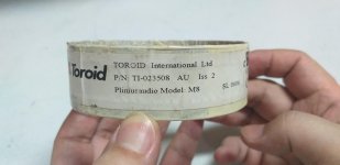
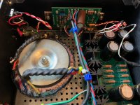
2 - 910VA R-Core transformer (Kitamura Kiden).
3 - 60,000uF cap
The bad:
1 - Single PCB for all 5-channels+protection, thin Cu layer on PCB prone to failure.
2 - Asymmetric PSU - separate power transformers (546VA + 364VA = 910VA) and filters for 2-ch + 3 ch amps.
I have some experience in circuit and PCB design and frankly i am less than impressed with the skills of Nak designer. There was no need to keep it to a single PCB, could have used fiber instead of thin Bakelite PCBs, too much component cramming, etc.
Few options I have considered:
1 - Re-cap, may be swap some components with premiums. Live with the units until they are beyond repair..
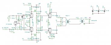
2 - Since I also own a Nak TA-3 (75Wpc, STASIS) and it is the best amp i have ever heard, I thought why not use either Nak TA-4 / PA-5 / PA-7 design to make my own clones. Use the PSU +/- 60Vdc rails of the unit as is, use the schematics from service manuals to design my own PCBs and I will be good to go.
Well, I went through the schematics of all the Nak units, seems like they are too old and many components are not available. Trying to source components that are already obsolete or going into the complexity of figuring out replacements seems too much hassle.
Is it still possible to make 100W STASIS?
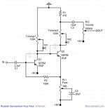
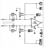
3 - Secondly, I went through the Peeter's "X100 back engineered" thread. It seems like a good replacement for papa's STASIS and biased slightly into Class-A like Nak PA-7, it should surpass PA-7.
Basically I want something primarily Class AB with some high-current capability with slight Class-A bias (if possible in the chassis space) primarily meant for HT multi-channel duty.
All DIY Pass designs I have come across focus on Class A. Perhaps because most people into DIY want something really clean sounding for stereo duty.
What do you guys recommend?
PS. Since Mr. Pass is very lenient with DIYers using his designs for personal, non-commercial use, I am hoping I can use one of his old Class AB designs..
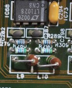
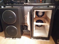
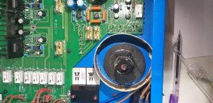
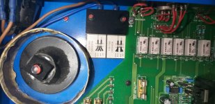
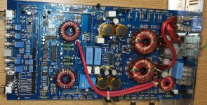
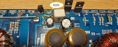
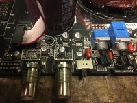
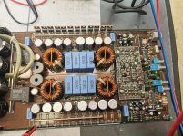
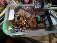
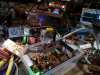
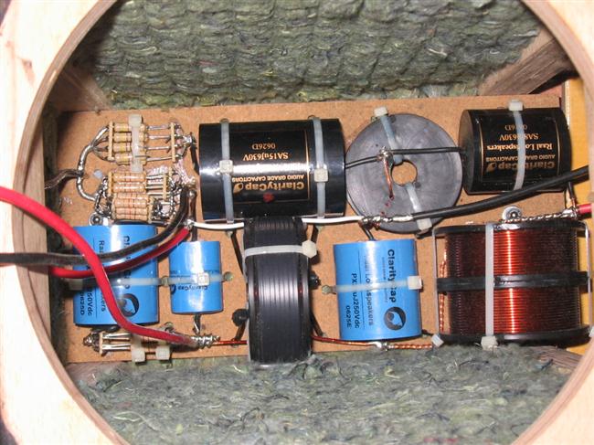
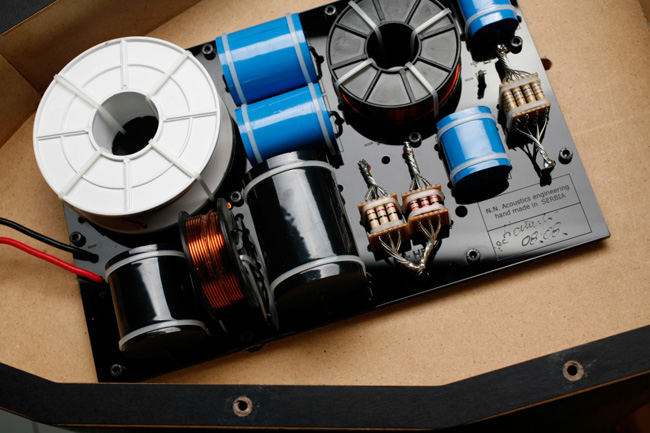
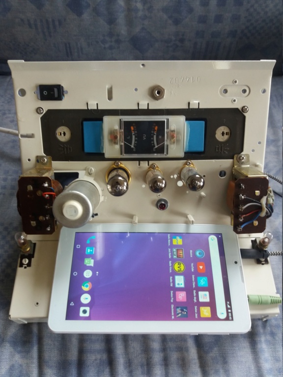
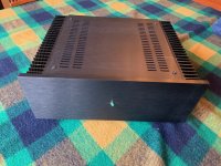
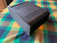
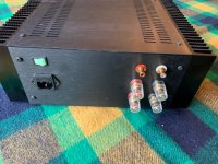
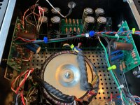
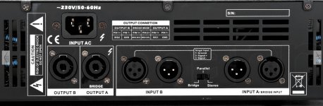
PA-1, undressed!


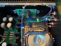


![IMG_3259[1].jpg](/community/data/attachments/771/771140-57a1562d387e688def0da9944073c496.jpg?hash=V6FWLTh-aI)
![IMG_3260[1].JPG](/community/data/attachments/771/771160-5ebe85022ad1bd8db26e82e131e5fc5c.jpg?hash=Xr6FAirRvY)
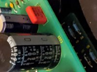
![IMG_3258[1].jpg](/community/data/attachments/771/771187-3537a326d7b2463e2290057fa356e63b.jpg?hash=NTejJteyRj)