Hi all,
'ts been a long time. How's everyone doing?
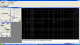
I'm working on this amp, which I recapped, adjusted, measured (fairly well - enclosed), and played for hours, until there was a POP!, and I lost both channels.
Smelling something too hot for comfort from the speakers protection board (it's an early model), I measured DC voltages coming into the protection board from the outputs and I get 0.85V for one channel and 1.38V for the other. Obviously, humongous. No wonder the protection boards clamps both channels to no output (base of Q110).
Obviously, at the end of my adjustments, the values for bias and offset were pitch perfect.
It seems some sort of failure occurred, but why on both channels, and why so similar a failure?
I am torn between pulling final Qs out (which would be painful, as they're soldered), and investigating the differential input to see if a large unbalance has occurred (but why?). Maybe do some voltage-resistance on all stages, starting at end, against schematic.
Any input welcome!
aR
'ts been a long time. How's everyone doing?
I'm working on this amp, which I recapped, adjusted, measured (fairly well - enclosed), and played for hours, until there was a POP!, and I lost both channels.
Smelling something too hot for comfort from the speakers protection board (it's an early model), I measured DC voltages coming into the protection board from the outputs and I get 0.85V for one channel and 1.38V for the other. Obviously, humongous. No wonder the protection boards clamps both channels to no output (base of Q110).
Obviously, at the end of my adjustments, the values for bias and offset were pitch perfect.
It seems some sort of failure occurred, but why on both channels, and why so similar a failure?
I am torn between pulling final Qs out (which would be painful, as they're soldered), and investigating the differential input to see if a large unbalance has occurred (but why?). Maybe do some voltage-resistance on all stages, starting at end, against schematic.
Any input welcome!
aR
Attachments
-
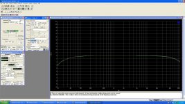 Sony TA-3200F Ampl vs Freq - ADJUSTED - 03-08-2020.JPG288.9 KB · Views: 330
 -
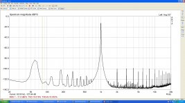 Sony TA-3200F ARTA 1.4V in 2.8V out L - ADJUSTED - 03-08-2020.JPG197.2 KB · Views: 346
 -
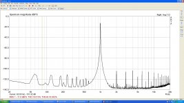 Sony TA-3200F ARTA 1.4V in 2.8V out R - ADJUSTED - 03-08-2020.JPG193.2 KB · Views: 327
 -
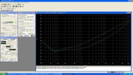 Sony TA-3200F crosstalk vs Freq B is green - ADJUSTED - 03-08-2020.JPG287.6 KB · Views: 323
 -
 Sony TA-3200F THD+N % vs Freq - ADJUSTED - 03-08-2020.JPG302.1 KB · Views: 309
Huge DC offset would be seeing rail voltages at the output... the values you measure are very small (for a fault condition) and also suggest something common to both channels.
First check is always on all the supplies internal to the amp including any common reference voltages within the circuit. You may find one low voltage rail is low or missing somewhere.
As always (and we see this so often on the forums as recaps go wrong) recheck all your previous work.
First check is always on all the supplies internal to the amp including any common reference voltages within the circuit. You may find one low voltage rail is low or missing somewhere.
As always (and we see this so often on the forums as recaps go wrong) recheck all your previous work.
Thank you, Mooly - the presence of the symptom on both channels indicates PS issues, as you point out. I appreciate the clarity, which is exactly what I needed.
Hopeful to get some bench time tonight and will report the findings here. First order of business - rechecking the caps orientation. Second, check the actual voltages against schematic.
Thank you very much for your input!
Hopeful to get some bench time tonight and will report the findings here. First order of business - rechecking the caps orientation. Second, check the actual voltages against schematic.
Thank you very much for your input!
Got some new data today.
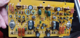
The differential input seems to be very unbalanced: Collector of Q101 is at -56.3V while Q102 has a more expected -63.3V. I also don't see measurable current through R111 (barely a fraction of volt over it), so I am running under the assumption Q101 is busted.
The same measurements apply to the other side. How can this happen? Well, my fault entirely. I missed snipping the legs off of C115, C215 in that snake nest of wiring that's back there, and so they were collapsed into themselves when I fit the board back into its cradle and they may have shorted. Not 100% sure this is exactly what caused this - especially as it measured well and ran for hours under these conditions - but it's likely the root cause of my issues. Bad form, what can I say.
I am assuming I ruined Q101 and Q201. They are part of pairs which are very strange in my unit - it seems they mixed an 2SA706 and a 2SA705 on each pair (why?!?). Despite their name, they are completely different transistors - 2SA706 is a TO202, 2SA705 is s small signal plastic case transistor. I have no explanation for why this would be. The service manual calls for 2SA621 in a symmetrical pair. Per my info, this is an early production unit and the respective service manual applies.
So anyway, the closest I have - per specs on all these parts - is MPSA55. Though Vcbo/ceo seem a bit low compared to what the circuit is doing - applying over 60V voltage drop over the transistors (though, again, the original parts are in the same predicament). I may drop these in tonight and give it a test.
Attachments
Last edited:
Alright. So further progress on this. Or lack thereof.
As presented in previous post, replaced the differential input pair with MPSA55s. To account for this, I placed the DC balance pots (R141/R241) midpoint, and tried to restore 0V at outputs. No luck, the previous readings have maintained.
I've had other unruly voltage readings during this morning's mapping, but I thought I should start with the input circuitry, as it seemed a reasonable assumption something on there is awry. A bit at a loss what next step is.
BTW - other than the forgotten legs, polarization of all caps checks out.

For a vintage amp, there are many parts become unreliable due to years working and at the year of production, semiconductors supply was limited and cannot compare to current variety new transistors supply.
To restore a vintage amp, we will to do it in two ways, one way to keep original parts as possible, we need desolder and test all items(maybe apply power load test for some transistors for sure functioning, all components like resistors, mylar capacitor cap, diodes and transistor etc), the other way is just replace all components to new items which apply for the amp circuit to make it work but maybe a new sounding for a vintage amp.
We also need to check the PCB layout traces, soldering joints, connection cables, VR and switches contact condition ok or not.
also check your brown / gray / orange / gold resistances (1.8k) right next to your potentiometers and your potententiometers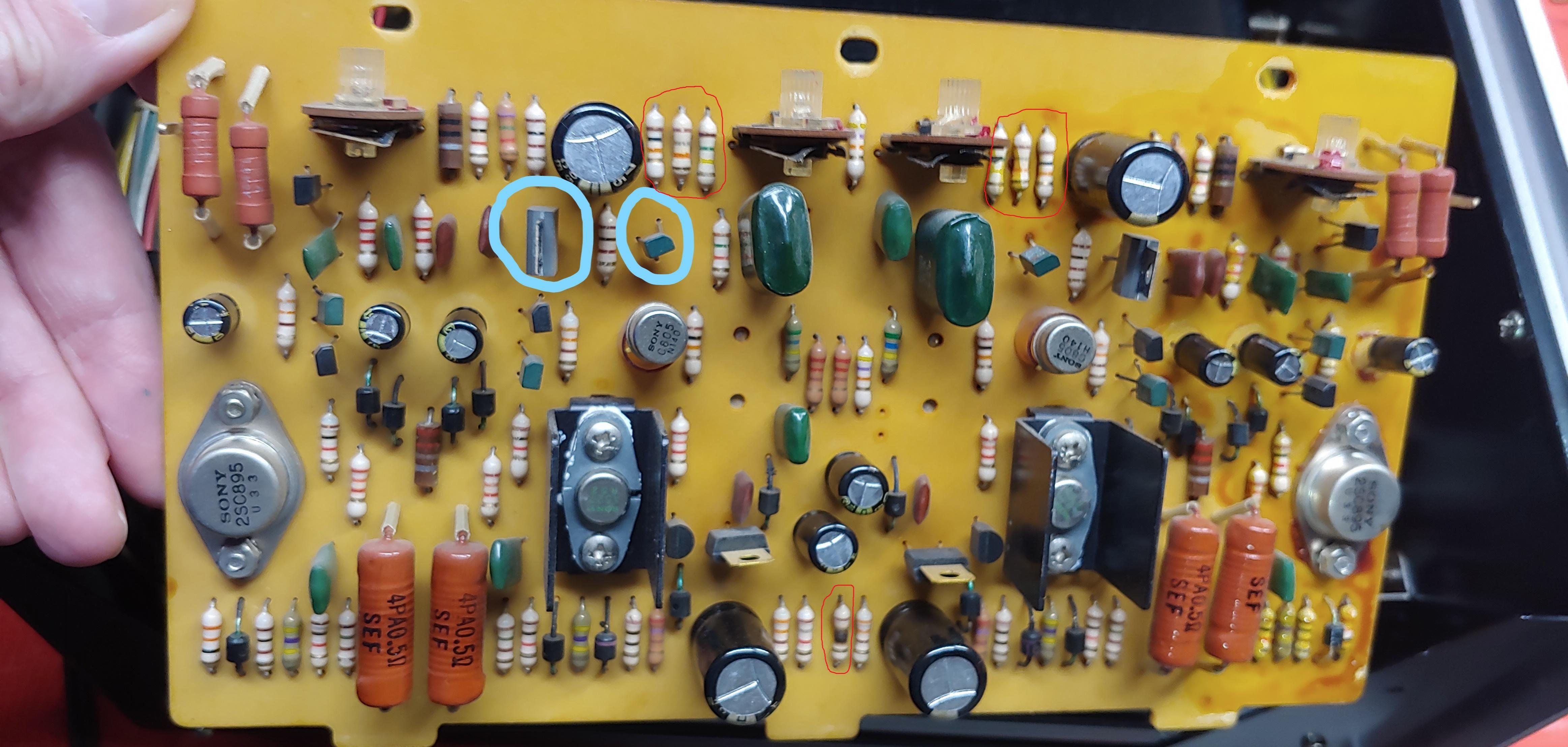
Thank you, huggygood, didn't see that. I replaced both R113/R213 with CMF55s 1.74k to no avail. No change to the observed faults.
Further response to huggygood:
I don't have higher voltage transistors currently. I do have some KSC1845 (which I used occasionally in some Mc repairs), and so maybe I'll add some KSA992 (so I'd put together complementary pairs). I assume KSA992 should work for this purpose (120V part).
In the meantime, I may pull legs of some of the resistors you indicate and some others on there and see if I can find more failed ones. The blackened R113, strangely, measured fine after pulling. But the stress on that resistor makes me weary of Q103 too, though. KSC1845 (which I have) seems like a fit replacement for that 2SC805 though.
Further response to huggygood:
Sorry, this response was rather addressed to Patrick101...
I checked R103, R104, R106 (and 2.../other channel) and they all check out fine.
I then realized the DC balance adjustment circuitry is the same for both channels (R308, R309, R310, R311) and checked those too. Jackpot, I thought, as this is the kind of circuitry common to both channels, and voltage referencing, Mooly was taking about - but no luck, the all check fine. Except, R309/R310, which should be 100ohm (per earliest service manual I am aware of), are in this case 220ohm. Maybe accounting for the weird, dissimilar differential input pair parts? I mean, in the sense of not conforming with what the service manual calls for. But they do match their markings. The only service manual voltage I can check is the 0V for the R141/R241 wiper, and that's what I'm seeing on there.
While at it, I replaced the unfortunate C115/C215, and checked D101 and D201 for drop (0.59V/0.56V). Can't find anything really wrong on here. I am pretty sure the diff pairs Qs have not yet failed, with all the excessive drop over them. I will still order the KSA992s for sleep factor, and replace.
The power supply seems pretty solid, if a bit under the specified voltages - +-66V vs. +-70V; +-63.8V vs. +-67V; +-61V vs. +-63V.
With the MPSA55s in place, I get pretty much the same readings (and imbalance) as before.
Yes, KSA992 can replace Q101,Q102 2SA621, KSC1845 can replce Q103 2SC805
For me to repair these amp, I would disconnect one channel power supply and only repair one channel first, it is more easy to find out the problem, once one channel repair successful, the other channel repair will be more easy.
For me to repair these amp, I would disconnect one channel power supply and only repair one channel first, it is more easy to find out the problem, once one channel repair successful, the other channel repair will be more easy.
It would be worth checking the amp isn't oscillating as that can give rise to an apparent DC shift in output, particularly if it is asymmetric in nature.
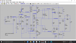
For reasons that elude me I found I have a LTspice simulation for this amp... must be another thread somewhere from the past.
For reasons that elude me I found I have a LTspice simulation for this amp... must be another thread somewhere from the past.
Attachments
Thank you, Mooly.
What just came to mind is that, when I turn this on - I'm doing this in my garage, where I have a fairly flimsy line power service - the lights go a little dimmer for a moment, like there's a surge at turn on. Maybe something's in near short - like a power transistor or something similar. Though it may just be the charging of the can electrolytics (which I replaced with 12,000uF). Also, maybe auto-oscillation could do this too.
What just came to mind is that, when I turn this on - I'm doing this in my garage, where I have a fairly flimsy line power service - the lights go a little dimmer for a moment, like there's a surge at turn on. Maybe something's in near short - like a power transistor or something similar. Though it may just be the charging of the can electrolytics (which I replaced with 12,000uF). Also, maybe auto-oscillation could do this too.
The lights dimming will just be the surge current of the transformer and it can vary each time depending on the state of magnetisation of the core (where in the 360 degree cycle it was when you last turned it off) and where in the cycle it is when you turn it on. So all normal there really.
It would be worth checking the amp isn't oscillating as that can give rise to an apparent DC shift in output, particularly if it is asymmetric in nature.
For reasons that elude me I found I have a LTspice simulation for this amp... must be another thread somewhere from the past.
Mooly - shall I take the alternate parts shown in the schematic (2N5401, etc.) roughly confirmed for this application? Preparing a parts order and will add some Qs for any needs on this.
The 2N's etc are all just standard generic parts that are commonly used (in simulation as well as real build) but while they may well be OK they can't be 100% guaranteed to result in a stable (no oscillations) repair without testing for real using a scope etc.
Using them may require some small tweak of a component value.
Using them may require some small tweak of a component value.
- Status
- This old topic is closed. If you want to reopen this topic, contact a moderator using the "Report Post" button.
- Home
- Amplifiers
- Solid State
- Sony TA-3200F: huge output DC offset