The 2N's etc are all just standard generic parts that are commonly used (in simulation as well as real build) but while they may well be OK they can't be 100% guaranteed to result in a stable (no oscillations) repair without testing for real using a scope etc.
Using them may require some small tweak of a component value.
Got that, Mooly. I placed an order with most of these thingies, just so I have parts handy in case.
I assume an oscillating amp should show some dirties at output (or along signal path), via scope. Or maybe I should employ AP box + EMU0404/ARTA, which would bring the frequency domain examination benefit.
I haven't had one do that, I'm not entirely sure how I'd check. Welcoming any pointers.
A decent wideband scope (not a USB thingy) should show any oscillation clearly. If all you see is a clean DC offset then it's not oscillating, on the other hand if you see some significant HF present then that may (on the scope) still appear centred around the 0V point and yet confuse a DVM into showing an offset.
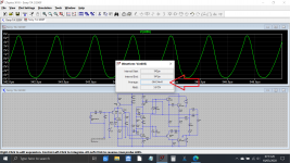
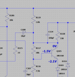
Even the simulation can easily be prodded into instability. Look at the asymmetric nature of the oscillation and how it gives an apparent DC reading even though it appears centred around zero volts. This is the main speaker output. The frequency is around 1.5Mhz.
Even the simulation can easily be prodded into instability. Look at the asymmetric nature of the oscillation and how it gives an apparent DC reading even though it appears centred around zero volts. This is the main speaker output. The frequency is around 1.5Mhz.
Attachments
No oscillation I can discern - <5mV AC on output, which to me its likely just noise. Clean as a whistle.
I think I need to extend my investigation to shape of Q103, Q104. I also got better fitting parts for all Qs, though, again, I doubt any of my replacements failed. They may be well stressed at the applied voltages.
I think I need to extend my investigation to shape of Q103, Q104. I also got better fitting parts for all Qs, though, again, I doubt any of my replacements failed. They may be well stressed at the applied voltages.
Last edited:

Here's some partial information (while I continue drawing the circuit in LTSpice - btw, where the heck is the potentiometer? I downloaded files off of this community, but I can't seem to be able to load them).
These are voltages actually measured while symptoms are on. Some voltages may be measured with the original 2SAs, others with the MPSAs (different days), but it didn't seem that there are significant variations between them. I may remeasure everything tonight, possibly after I get 2N5401s etc. in there.
Thank you!
Attachments
Mooly and all,
I'll really need to review this, as it's late and I've been at this for a while, but here's a provisional asc file for the schematic. I am no wizard at LTSpice, so I still need to populate this with supplies and other peripheral stuff. It takes me more time that it would someone versed in this.
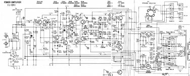
But this should at least emphasize this is an early TA-3200F. For instance, the current source on the differential input is missing. Other differences may apply.
As I said before, I also have a later one (may be very close to yours Mooly), and due to the differences, I can't wait to get that other one up and running - the design details seem to point to a better concept. So a better sounder, chances are.
More tomorrow. No time on the bench today due to contingencies. Just virtual bench via LTSpice...
On the voltage readings - isn't it a sign of illness that the differential pair is so unbalanced? I'm referring to the collectors of Q101, 102, sitting at almost 10V difference, which is about, what, 10%? I don't think this should be this large. Stepping back and looking at this big picture - it worked absolutely flawlessly for hours after adjustments and AP measurements, and then a POP! and there's no sound. A part failed catastrophically, I wager.
Cheers! Tongue in cheek.
I'll really need to review this, as it's late and I've been at this for a while, but here's a provisional asc file for the schematic. I am no wizard at LTSpice, so I still need to populate this with supplies and other peripheral stuff. It takes me more time that it would someone versed in this.
But this should at least emphasize this is an early TA-3200F. For instance, the current source on the differential input is missing. Other differences may apply.
As I said before, I also have a later one (may be very close to yours Mooly), and due to the differences, I can't wait to get that other one up and running - the design details seem to point to a better concept. So a better sounder, chances are.
More tomorrow. No time on the bench today due to contingencies. Just virtual bench via LTSpice...
On the voltage readings - isn't it a sign of illness that the differential pair is so unbalanced? I'm referring to the collectors of Q101, 102, sitting at almost 10V difference, which is about, what, 10%? I don't think this should be this large. Stepping back and looking at this big picture - it worked absolutely flawlessly for hours after adjustments and AP measurements, and then a POP! and there's no sound. A part failed catastrophically, I wager.
Cheers! Tongue in cheek.
Attachments
Last edited:
It would be worth checking the amp isn't oscillating as that can give rise to an apparent DC shift in output, particularly if it is asymmetric in nature.
For reasons that elude me I found I have a LTspice simulation for this amp... must be another thread somewhere from the past.
Mooly,
A couple of roadblocks with this:
- It requires an external file ("discrete models.txt"). Can you provide that?
- I am having a hard time adding lib models to LTSpice... I have downloaded PSpice models for MJE340, MJE350, and MJ21194, to use instead of the pre and finals, but can't figure the import procedure. Sorry if this sidetracks the thread...
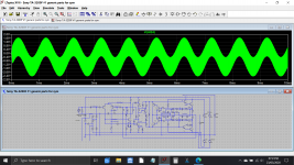
OK, I have some sort of simulation - I used some best guess parts from the main library everywhere and I get no error. I don't get any signal out though.
I am playing with this right now, but any glaring mistakes, please feel free to point out.
Thank you.
I am playing with this right now, but any glaring mistakes, please feel free to point out.
Thank you.
Attachments
Here you go. Lots of ways of doing this but I add the model file to the root of the C drive as shown here. Just copy and paste it into place. You can rename the file to whatever suits you if you want. Doing it this way means it can be called from any LT file anywhere on the PC as long as you add the:
.include C:\discrete models.txt
directive on all your LT files.
It has to be in a zipped folder because it comes in at just over the forum size limit for a text file.
I'll have a closer look later 🙂 been busy with home diy stuff all day.
.include C:\discrete models.txt
directive on all your LT files.
It has to be in a zipped folder because it comes in at just over the forum size limit for a text file.
I'll have a closer look later 🙂 been busy with home diy stuff all day.
Attachments
Does Q103 collector really go to the emitter/s of the differential input stage ?
That looks wrong to me. Also R110 doesn't quite look right in the way its configured.
That looks wrong to me. Also R110 doesn't quite look right in the way its configured.
OK, so its making a bit more sense how its configured. Scrub the above comment for now 🙂
The offset seems to be because of insufficient current in the front end... it would be worth checking the resistors are correct. I can get the amp DC stable by lowering R106 but there is another issue with bias current.
R119 would be passing 35 ma under quiescent conditions which seems far to high. Worth checking that area for configuration of the bootstrap and the values.
Is there a resistor missing that should be connected in series with R119 ?
Thank you, Mooly, very helpful.
My plan for tonight is to:
- replace MPSA Qs with 2N5401s etc.
- verify all resistors around the input are within expected values
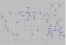
For reference, I include a snip of the early version's schematic (hopefully legible). I will be double checking my spice, but I think I followed it OK. I've also been spot checking the actual amp against the schematic, and except for the odd, dissimilar input LTPs, it seems to be matching.
Per this, R119 should see 10mA through. I have not checked the voltage at the lower leg, but will, to add some empirical data to where the amp sits in terms of OP.
Thank you, again, Mooly, for thinking on this with me.
My plan for tonight is to:
- replace MPSA Qs with 2N5401s etc.
- verify all resistors around the input are within expected values
For reference, I include a snip of the early version's schematic (hopefully legible). I will be double checking my spice, but I think I followed it OK. I've also been spot checking the actual amp against the schematic, and except for the odd, dissimilar input LTPs, it seems to be matching.
Per this, R119 should see 10mA through. I have not checked the voltage at the lower leg, but will, to add some empirical data to where the amp sits in terms of OP.
Thank you, again, Mooly, for thinking on this with me.
Attachments
Last edited:
Thank you, Mooly, very helpful.
My plan for tonight is[...]
Thank you, again, Mooly, for thinking on this with me.
Of course, all this is PST "tonight." I'm pretty sure you're on quasi-opposed schedule.
And also, of course, this is when your desoldering station takes a dump and needs to @^^%!$&#@%^&! So, unless I intend to lift all pads from a very old PCB, I'll have to wait for replacement parts, fix my desoldering station. and continue the troubleshooting in the next few days.
Before my gear giving me a hard time, I managed to confirm R119 sees 10mA through it.
In the meantime, I can keep the flame burning here mostly with Spice material and such.
PS:
R218 = 4.8k
R219 = 1.8k
R119 = 1.78k
R118 = 4.75k
All 1W, so intended to be able to see relatively high currents.
Just to continue establishing the groundwork.
R218 = 4.8k
R219 = 1.8k
R119 = 1.78k
R118 = 4.75k
All 1W, so intended to be able to see relatively high currents.
Just to continue establishing the groundwork.
It looks like the 4k8 is missing from the sim which explains the high current and incorrect bias adjustment. 6 to 10 ma would be a typical VAS current for that part of the circuit and we know that with a 60 to 70 volt supply that the combined resistance has to be somewhere around 65/0.006 to 65/0.010 giving around 10k to 6k5.
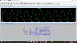
Lets see what happens... this is a running commentary...
So current now at 9ma, DC conditions basically OK but bias still high. The two series diodes seem to be creating to high a volt drop. Also the amp is unstable now. I've replaced them with shottkys... still to high and unstable.
Think we will have to remove one of the diodes... unlesss... yep, its the driver transistor causing that problem. Now using MJE340 and MJE350. Bias sets correctly now.
Still unstable though.
Zobel network added... all good 🙂 off load, no good on load... and just spotted it. The PNP driver is upside down 😱
Bias now high again... is there a missing resistor between B and E of the upper NPN output?
I'm going to add one. 220 ohms sounds reasonable. Bias lower now but not low enough.
Time for some different outputs, MJL21194C. Now we have an offset, that's odd. I'm going to add a similar 220 ohm to the lower output.
Stable and bias now adjusts to 100ma 🙂 Latest file attached.
(7:30 am here)
Attachments
Wow, Mooly, a pile of thank yous for all this!
A couple of quick notes:
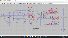
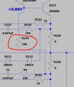
- There's a resistor (R134) which I don't know where to place... This is because of a crease to the original scan or whatever. Will seek to identify on the actual board and see where it connects. May explain why some of this is still off.
- I couldn't figure out for the life of me yesterday how to add the MJ transistors to my LTSpice. Still can't (though I'm still working my way to the first sips of coffee this morning, so not yet at much capacity...). Can you pretty please share some hints? I think I'm so lucky as to already be talking to the LTSpice resident specialist... 😉
To this end, I've downloaded lib files for the transistors. Not sure what the next step is there.
Thanks!
A couple of quick notes:
- There's a resistor (R134) which I don't know where to place... This is because of a crease to the original scan or whatever. Will seek to identify on the actual board and see where it connects. May explain why some of this is still off.
- I couldn't figure out for the life of me yesterday how to add the MJ transistors to my LTSpice. Still can't (though I'm still working my way to the first sips of coffee this morning, so not yet at much capacity...). Can you pretty please share some hints? I think I'm so lucky as to already be talking to the LTSpice resident specialist... 😉
To this end, I've downloaded lib files for the transistors. Not sure what the next step is there.
Thanks!
Last edited:
Using models is the one thing I struggled with (and still do tbh). I tend to stick to the same method/s tbh (once I'd figured it all out) and that works like this.
You need the models as a text file. Lets take the MJL21194C and MJL21193C and the MJE340C and MJE350C which I'm using in this sim.
I've pasted just those four models into notepad and called the file 'Sony amp models'.
That file is attached to this post and so is a re save of your file under another name.
Now I add a directive to the sim saying:
.include Sony amp models.txt
As long as you keep the .asc file and the txt file in the same place which can be documents or a dedicated folder anywhere on your PC the sim will call up that file. The two must always be in the same place though, folder, directory etc.
That's fine and works well but gets messy if you want lots of separate folders with lots of sim files in them... so that is where having a master file come in. As long as you incude a spice directive to the location it will work. I paste the big model file (hundreds of models) direct into the root of the C drive.
So if you download these two files and they go to your 'Downloads' folder then the .asc should click and run. Move the .asc somewhere else and you must move the .txt file along with it.
Attachments
- Home
- Amplifiers
- Solid State
- Sony TA-3200F: huge output DC offset