Switching Power Supply Questions

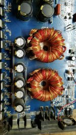
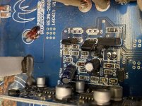
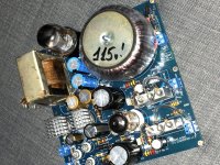
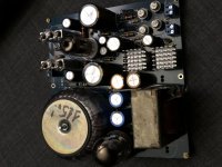
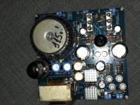
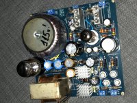
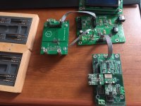
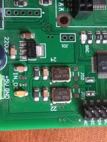
I have two old Nuforce Ref9 amps. One with a blown power supply. They are old Skynet power supplies that are single rail (I'm not even entirely sure what that means), dual-voltage 48V and 5V aux. I have been searching for a replacement and have found many things that are very close but nothing that seems to be exact.

First, I found a brand that looks well-made named Cosel but I have not found any use in audio. They look more industrial. I would also need a small step-down device for the 5V circuit. Is there any reason to think that this would not be suitable for audio?

And I am assuming I would add one of these to make the circuit work.

There is also this Chinese option but it is 46V not 48V. Is this too big a deviation for reliable operation?

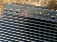
Then, I am completely unclear on how closely matched the auxiliary voltage needs to be. I am not even entirely sure what it does. Does it provide current for a soft start? The power light LED is wired to it, that is for sure.

And last, after it's all replaced, should the fuse be paired to the power supply or the original spec.

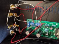
I am feeling entirely out of my league on the specs, I just want these things to work. My overall technical prowess is about as good as swapping the power supplies between the two units to determine it is the power supply that is bad, not the amp board.

Thank you in advance.

Xion X7 Kraken 1500.1D

Hello friends, someone with information about this amplifier, I am missing the value of R39 and what diode does it have in D21? and what values ​​or signals should i see in the ic IR2184S regards

Attachments

  • Screenshot_20200629-152145_Gallery.jpg
    Screenshot_20200629-152145_Gallery.jpg
    365.8 KB · Views: 121
  • Screenshot_20200629-152102_Gallery.jpg
    Screenshot_20200629-152102_Gallery.jpg
    477.8 KB · Views: 110
  • Screenshot_20200629-152216_Gallery.jpg
    Screenshot_20200629-152216_Gallery.jpg
    427.5 KB · Views: 114
  • Screenshot_20200629-152120_Gallery.jpg
    Screenshot_20200629-152120_Gallery.jpg
    633.5 KB · Views: 123
  • Screenshot_20200629-152128_Gallery.jpg
    Screenshot_20200629-152128_Gallery.jpg
    585.3 KB · Views: 132

SAE model a105 subwoofer power amplifier input options

This SAE model a105 subwoofer power amplifier is two channel and has speaker line inputs for the left and right channels. It outputs to left and right subwoofers.

I am of little brain but believe that the current from the amplifier speaker out is different than the pre-amp to amplifier out.

Is there a line buffer or some fix to use the pre-amp subwoofer out's from my HT pre-amp as input to the a105 speaker inputs?

If anyone has any leads or links to the manual that would be very helpful. I can't seem to find it.

Much obliged.

Teres Audio going out of business?

I have been trying to get some info from Teres Audio and I haven't received any replies to my emails.

I have a Teres 255 table and just want some info on replacement parts and about maybe a possible Versus purchase.

Chris used to answer email promptly before. I did some searching on the web and came across some info about Chris being the "former" president of Teres Audio.

Does anyone here know what's going on at Teres Audio?

Newbie question about RCA and speaker connections

hi all

I'm building a little 10 watt stereo chipamp, nothing complicated or spectacular, purely as a learning exercise.

The amp board has 3-way screw terminals for both input and output. The input terminal has Input 1, Input 2, and a ground, the output terminal has Output 1, Output 2, and a ground.

I'm slightly confused as to how I wire up my connections to these. At the moment I have connected the positive of the L and R channel RCA jacks to each of the inputs (L to input 1, R to input 2). The grounds of both RCA jacks are connected together, and a wire from this is connected to the input ground terminal.

I have connected the negative terminals of L + R binding posts together, and connected this to the Output ground terminal. The positive of the L binding post goes to Output 1, and the positive of the R binding post goes to Output 2.

But this doesn't sound right, it sounds like I've wired it out of phase, and the right channel is much louder than the left. And I'm getting a lot of popping and buzzing (which may be just because I haven't yet dressed or shielded the cables). I haven't grounded either the RCAs or the speaker cables to the chassis, and I'm not sure if I should.

A picture is worth a thousand words, the attachment hopefully makes clear what I'm talking about.

Please don't laugh, I know this is basic stuff, but we all have to start somewhere.

Thanks!

Attachments

  • IMG_20200701_112206.jpg
    IMG_20200701_112206.jpg
    979.6 KB · Views: 195

NAD 705 in protection

Dear brains.

A friend of mine has asked me to take a look at his Nad 705 receiver that refuse to leave protection when powered on. I found the reason for this being 13VDC on the left channel output.
I can measure and solder, but my engineering-skills are pretty non-existing, so before I start destroying the board with experiments, I would be very grateful if you guys would take a look at my findings.
No magic smoke has been released, and nothing seems to get too hot when left powered on.
All other voltages than the ones written in red, are spot-on.
If I was to take a stab at the problem, I would think that Q107 was dead in an 'open' state, but as this is close to being a clean guess, please let me know if I'm wrong.

Thank you very much for your time.

Attachments

  • 705_lc.jpg
    705_lc.jpg
    282.6 KB · Views: 228

Shunt Feedback 6384 SE Amp

One of my daughters was disappointed in her grade in her high school engineering/design class, so I told her to email her teacher and see if he would give her some extra credit if she designed a tube amplifier with me and sent him writeups of the design process. He accepted the proposal.

I happened to have a pair of Edcor 5k:8 SE transformers and a pile of used 6384 tubes, so I decided they would go together to form the basis for the amp. I've had good results with 30% shunt feedback in a push-pull amp I built and I recently read an old article about an amp with a first stage transconductance amp (V-to-I converter) implemented with an op-amp and transistor that drives an output stage with a plate-to-grid feedback resistor for 100% feedback. Results presented in the article were impressive.

I figured this fairly simple arrangement would offer a lot to teach my daughter and could be built and measured in the remaining time of the school year.

Then after that, I could work on replacing the op-amp/transistor stage with some different tube circuits I have been kicking around for the V-to-I converter and measure performance differences from the solid-state circuit.

I think this approach has the potential to be a super-performer and be fairly simple. I suspect that the transformer will be the dominant source of distortion in the amp.

Anyway, I plan on chronicling the design and testing here for those interested in this approach.

Attachments

  • IMG_20200403_105352484.jpg
    IMG_20200403_105352484.jpg
    950.1 KB · Views: 835

Got a free enclosure; burn it or use it?

I stopped at a yard sale while they were cleaning up for the day. Guy gave me an enclosure that was actually made to fit my exact truck and even has the matching tan carpet on it. Looks homemade, but solidly constructed.

I can figure out the volume, but the way it's made has me confused.

It is one shared volume cut for two 12s with a short 3" single port on top. I thought shared volume was a no-no, (other than isobaric) but I've only ever built two ported enclosures. Is this a viable design, or did the guy just do a hack job? How do two subs work sharing the same ported volume?

Attachments

  • sub enclosure.jpg
    sub enclosure.jpg
    263.4 KB · Views: 152

Predicting DACs sound quality by FFT

Hi,

I've been trying to measure THD of several DACs and then compare the sound difference.
So I have about 10 different DACs (from ES9038Pro based to PC embedded), measured their harmonic spectra (at 1kHz 0db with notch filter) and then compare their sounds in pairs (on the same signal source and the same amplifier / speakers / headphones, with switching DACs "without looking", a couple of my friends were involved into the listening)

The measurements-to-listening results were generally predictable and matched the theory, some curious things were observed though. However there is a riddle I'm trying to solve.

The matched the theory and expected results
- The higher THD the better sound (the most obvious and expected of course)
- The sound quality is determined rather by a highest harmonic absolute level than by THD (RMS of all harmonics)
- Higher (5,7,11-th) harmonics are definitely more noticeable than (2-3rd)
- All the DACs with highest harmonic level below -100db sounded nearly equally

The curious observations
- Left and Right channels of the same DAC can have different harmonic levels. The difference can be up to 8-9 db
- Some DAC (devices) based on not too highly rated DAC chips can easily compete with award wining DAC chips based devices producing very good results.

The puzzle is with a single USB sound card.
Its sound is very noticeably worse the "competitors", but its FFT looks decent enough.
It's obviously not the best, high harmonics are at -110db, low harmonics are at -96db, but several other DACs with the same parameters sound definitely better.

Most probably 1kHz 0db FFT is not too representative, so I tried different frequencies, different levels, IM measurements etc. None of them revealed what's bad with the DAC,
but its sound is definitely worse DACs with even worse THD.

What should be measured to reveal the DAC defect tehcnically, not just to hear it.
Using a dynamic signal anyhow maybe? Actually all the known measurements techniques are based on static signals. I'm lost in conjectures and need an advice

Thank you,
Serge

Medium-woofer High-Pass when crossed in the snap <200hz area ?

Hello,

I would please like to know if there would be a difference with two caps arengement for the high pass of a woofer-medium unit which XO is in the 100 hz/200 hz where there is a lot of energy and snap behavior in the music.

If the high pass of the woofer-mid is made of 250 uF and basic MKP caps are choosed, is there a noticeable sounding difference between these two arrengement please :

- 2 caps // : 200 + 50 uF
- 5 caps // : 50 + 50 + 50 + 50 + 50 uF

Theorically second is best because the divided inductance and better esr, but will it be hearable enough in real life, given the caps are MKP (CrossCaps from Jantzen in mind) ? Second solution is more bulky and expensive !
Should I also increase a little the serie resistors value if a former smooth foil lytic is swapped for the MKPs or the Z diference will be low enough not to be noticed during the playback ?

Many thanks.


Edit : I also assume less Z in serie is giving a lowered impedance of the driver, so a different crossover frequency number ? Or is just the spl that is changing and the driver impedance curve is not moving whatever the Z in serie before the voice coil ?

Help with an odd On Wall design please.

Hi all!

So my daughter is requesting a project design for a wall hanging art piece that will serve as a music system as well. Size limit is 24” by 48” and 3” thick.

It will hang on the wall with a French cleat and be totally self contained. Music source will be an Amazon Echo and it will be covered in a custom printed acoustically transparent material which I have already sourced. Stereo of course with an Amp module of some sort inside.

Wide off axis dispersion is preferred of course and decent low frequency extension. I have sourced this woofer which seems ideal for this application

https://www.parts-express.com/pedocs/specs/295-255--dayton-audio-lw150-4-spec-sheet.pdf

I’d like to keep this simple and my daughter is no audiophile.......loud, clear and good off axis response. So I’m hoping to be able to use the above woofer in a two way.......but can it mate with a dome tweeter or do I need a fullrange option instead?

My ‘thought’ was to pair them with the newer Peerless Corundum tweeter or DX25.....both of which have a low FS

Peerless DA25TX00-08 1" Corundum Dome Tweeter

https://www.parts-express.com/pedocs/specs/264-1478--tymphany-dx25bg60-04-spec-sheet.pdf

Will this work or will I need to do an array of fullrange drivers to work with the chosen woofer?

Please remember the MAX thickness of this thing is 3”. I’ve decided on 1/2” ply stock for the front and backs leaving a 1.5” internal volume for bass response. I need .6 cu ft for a pair of the woofers so that’s been worked out to .9 cuft volume all in including ports and minimal bracing. That leaves roughly .2 cuft for the Alexa, Amp, and tweeter displacement.

Thanks in advance for the long read!

Measuring woofers at 2.83V/1m/8 Ohms: with or without load ?

Hi,

I'd like to do some basic frequency response (SPL) measurements on 4 of my old 12" 4Ohms woofers (20+ yrs old, noname, no datasheet).

I have REW and a MiniDSP UMIK-1.

I thought I can do a classic measurement at 1m/2.83V/4Ohms (and then converted into 8 Ohms terminology, final response will be 3dB lower in reality than what I get here).


How do we measure to get not perfect, but acceptable results (no near-field yet) ?

1. signal is 50Hz, set volume pot 'til I measure 2.83V on the terminals unloaded ?

2. same as 1) but with the drivers attached ? (So, with real load).

3. same as 1) but with a dummy load of 4 Ohms resistor and then leave the pot as is, amp is 'calibrated' and finally change the resistor to the driver for the actual measurement ?

Amp is a little cheap $2 Class D module up to the task I think (25W RMS max). If the speaker is attached, speaker terminal voltages fall a bit below 2.83V (compared to unattached) and vice-versa, if I calibrate 2.83V on the amp with the volume pot while driver is attached, unattached the measured voltage is higher on the terminals.

Where's the truth ? (I assume I can do an amp volume pot 'calibration' to nominal value with a dummy resistor just to know the best pot setting for the measurement and then measure the speaker as a real load, but still not sure). Since amps are mostly voltage devices I don't think output voltage shall change at all between loaded and unloaded states but I might be wrong.

:worship:

Crosstalk in Windows ?

I did a strange observation: When using a Sinusgenerator or Rew or Winmls, so no matter which Software: When using only one channel as output, so 100% Left and 0% right: I got on the left channel 120mV, but I get a the same signal as well with 40mV on the analog out of th right channel.

Initially I thought it is a cable cross talk or a weakness of the internal Laptop-Soundcard. I changed than the Soundcard and the cable to a Roland Quad capture and cinch cable....same result.

Is there anything I could do to bring to right channel to 0V ?

Sofar I had my left and right speaker connected and liked to switch via software in REW to measure first left and than right....but now I learned that the measurements in the far field at least are wrong as the woofers of both speakers add up...in my case it was a subwoofer integration where the right speaker had suddenly deep bass while I had a subwoofer only active for the left channel.

LED bias for pentode driven 300B SET

Hello folks.
has anybody tried LED bias for pentode (e.g.EL84) driving a 300B SET?
I'm currently putting together a monobloc variation of the thorsten Loesch's "Legacy" (albeit more uF and a choke in the prereg stage of the PSU. The PSU caps are all polypropylene, and I'm keen to stay away from electrolytics throughout (Won't be able to lift the things in a few years to replace if I live long enough).

So the question is..... resistor/ cap versus LED cathode bias. Driver stage only.
The Thorsten driver stage utilises cap/resistor but has a very low current of 5.5/470 which suggests only a sinle series of LEDS, or is this biased very low (e.g compared to Morgan Jones red light amps output stages and so on).

Enlightenment/experience/musings (at c.a 650nm wavelength) would be much appreciated.
Ta
Andrew

need advice to replace 2SC2824 / 2SA1184 driver transistors

Hello there,

I am trying to fix a Luxman L-113A that distorts the left channel. I was able to detect that the 2SC2824 is going bananas and gets extremely hot.
I would like to find a suitable replacement for the drivers and easy to source. Also someone replaced in a previous repair, the transistors on the right channel for some BD ones, I would like to change those too.

The output transistor are 2SC2577 and 2SA1102 in case it helps to make the choise.

Thanks for any tip 🙂

Need a circuit or device that swaps left/right speaker output

Hey All, this is a weird request. Depending on where I sit in the room I'd like to be able to throw a switch on a box or DIY circuit that would swap the left and right outputs to my speakers from my amp. I'm thinking something that sits between the amp outputs and speakers (regular old banana plugs) where I could have:

Position 1: AMP L output ---> L Speaker and AMP R output ---> R Speaker

Position 2: AMP L output ---> R Speaker and AMP R output ---> L Speaker


Seems like this should not be difficult, though my google-fu fails me. This would be done in a regular analog 2-ch stereo amp/speaker setup. I understand the silliness of the question, but the potential solution has intrigued me.

Opamps for PCM1794 I/V conversion?

Hey there guys, I almost posted this in the Parts section, but figured it would get more relevant views and opinions here. I have a dual mono PCM1794 PCB I picked up a while back, and I'm getting ready to actually finish it. The only opamps that I have on hand are the OPA445, OPA547T, and a handful of OPA2132P. I have used the OPA2132P in the past for single-chip I/V with the PCM1794 and it worked well, but I wanted to order some other chips to try this time around, seeing as how I'm ordering parts anyway.

Please do not recommend off-board solutions, or alternative I/V schemes, that's not the intent at this time.


This is the style of board in question. The one I have is barebones, no DAC chips, I/V stage caps, or opamps. Perfect starting point 🙂

721212d1544473647-opamps-pcm1794-conversion-2018-hi-fi-parallel-pcm1794a-dac-audio-decoder-assembled-_57-jpg


It uses six single, and four dual opamps total, and I was wanting to spend 3~5$USD or so per chip.


I was thinking for duals, since they are used as the I/V stage chips here, I would try the OPA2132P that I have on hand, and maybe some LME49720/LM4562. I may grab some NE5532 just for comparison. I'm strongly leaning to simply using the LME49720 here. It has very good specs, and has a strong pedigree f great measurements, sound, and performance.

I also might have a set of four Burson V6 "Vivid" duals on the way to test out (samples for review) in this position as well 🙂


For singles, maybe the OPA132, OPA227, the usual I see used on these boards/builds is the NE5534, but it feels pedestrian to use these here for much other than comparison purposes. Maybe the OPA1611 on a browndog adapter? I was originally thinking LME49710, but it's unobtainium after going EOL.

Seeing as how the board uses the singles merely for differential-to-single-ended conversion, I'm not so sure a fancy-pantsy chip makes much sense here, based on prior experience, after a certain point.


Any comments would be appreciated.

Attachments

  • 2018-Hi-Fi-Parallel-PCM1794A-DAC-Audio-Decoder-Assembled-_57.jpg
    2018-Hi-Fi-Parallel-PCM1794A-DAC-Audio-Decoder-Assembled-_57.jpg
    94.2 KB · Views: 2,933

Troels C17 modifications

I mentioned these (OT) in another thread, and got several questions about my mods, so I figured it would be best to share it in a dedicated thread.

Ref: Vifa C17WH-

I built the (ver 4) some years ago, using QLN spare part C17 drivers. These are not exactly the same as the originals, since they have surrounds from rubber (-foam?). Measurements seemed very similar to what Troels presented, but possibly a little bit lively in the 1-2k area. However, the measurements from Troels seem to differ in this area too. I used the DT300+WG300 from Monacor as prescribed.
I have always been running them sealed by plugging the 'horn loaded BR'. I never liked BR bass. The 'cavity' next to the 'BR horn' is also filled with rockwool, and a layer of normal stuffing on top to keep the dust from the rockwool in place. This improve bass a bit, and was a visible improvement on the impedance trace of the upper woofer.

I was never entirely happy with them though, I ended up running them active for a long time, and even then, I was not too happy with all the EQ available etc. They did sound a better with the XO raised to 2k or above though.

I got tired of the active setup with subs, a lot of amps and cables, and never ending tuning of the system when moving something around. And when I built a JLH amp I relly liked, I figured I would try to 'fix' the sound of these C17's and go back to basic stereo with one amp and two speakers.

I tried several mods on the tweeters, changing the damping in the pole piece, trying with FF (which I removed according to Troels instructions). In the end I liked it a bit more without the rear chamber and no FF.
I have a theory that the relatively high resonance (phase and ringing) of the tweeter is 'magnified' by the big WG enough to disturb the sound. There is also some (subjective) harshness in the treble area that I never got rid of. I was able to improve the dip around 15k significantly while playing around with the stuffing and rear chamber.
I also tried to do some mods to the XO, but wanted to stay 'true to the original' only adjusting tweeter resistor and cap at first. Later I just did my thing based on measurements ans subjective impressions from listening. A little bit higher XO, rising response from bass to mid flattened(maybe because high efficiency was the target of the design), phase tracking improved.

I found this one day Test Peerless DX25TG09-04 (XD-270 F / 4) on the waveguide, and ordered the Peerless DX25tg59-04 tweeters, made the adapters, and adjusted the XO. Now things started to improve in the midrange, and also in the top end. After some time playing with the DX (removing FF among other things), I was still not entirely happy with the treble, so I ordered the xt25bg60-04, and treble improved. I always preferred falling response before, but with these I did not mind flat. The DX might sound a little bit better in the midrange, but overall, I definitely like the XT better.

After some time I wanted to try impedance correction on the woofers. This was a major lift for the bass 'tightness' too, I really liked it.

I attach some pics of the XO's I could easily find, I have to dig more for the rest, if more is requested.

Attachments

  • Peerless XO.jpg
    Peerless XO.jpg
    43.6 KB · Views: 792
  • DT300 fix.jpg
    DT300 fix.jpg
    19.7 KB · Views: 820

Hifonics BE35-2500.1D

This amp uses 12 IRFP064N’S for the power supply fets .

Something doesn’t look right here unless I’m over thinking this .

There is a spot for 4 driver transistors but there only 2 in this amp .

Is there supposed to be 4 or only 2 ?

Replaced the driver transistors (C3228) with BD139 .

Once I load the drive circuit all drive signal disappears .

Attachments

  • 7FDDF0A2-30F7-4B39-838B-03D291D8A48D.jpg
    7FDDF0A2-30F7-4B39-838B-03D291D8A48D.jpg
    999.1 KB · Views: 94

Adjusting input sensitivity on Hafler DH-500

I made a search on the net and specifically on this forum with no result.

Basically I run three amps in my system. A moded Quad 405, a moded Quad 606 and this Hafler. While the Quads have the input sensiivity set at 0.75v, the Hafler is set at 2.35v and therefore the volume is quite off.

I have the diagram but cannot locate the resistance that sets the input sensitivity. Anyone can help? And while I am there, perhaps I would even fit a potentiometer to make it adjustable.

Thanks in advance

Lee

NiceRack.jpg

Pearl 2 Crackling on Left Channel

I have a Pearl 2 phono preamp that I built 4 or 5 years ago. It has been working fine until yesterday. Now I am getting a crackling or static sound from the left channel with certain higher notes (for example a flute). The remainder of the music is unaffected but the crackling sits on top of the music and is intermittent (related to higher frequency notes). The right channel is fine. If I swap the Pearl 2 for another phono preamp, all is well - so it must be the Pearl 2.

I really like the Pearl but have no idea where to start troubleshooting this problem. Any suggestions will be greatly appreciated.

JL 300/4v2 Driver Board Via Damaged

Hey!

I've got a JL 300/4v2 that I'm working on repairing. One of the channels is out so I've pulled the driver board.

It appears that there was an issue with PIN 10 and while removing the board the via was lost on the top side of the main PCB. The bottom via is still intact.

From what I can see there isn't anything connected on the top side, but would love it if someone could confirm what PIN 10 should be connected to on the top, if anything?

Cheers 🙂

New old Stock tubes for Sale

All are boxed and unused

Raytheon USA NOS wire ended tubes

5744WB single high mu triode my 70 ra 17.5k £4.50/pair
5787WA cold cathode 100V voltage stabiliser £2/pair
5702WB single triode mu 25 Ra 5k £4.50/pair
5703WB signal pentode £4/pair

GE 6197 Video output pentode , nice and linear . £5/matched pair

UK postage £3

Attachments

  • p1010001.JPG
    p1010001.JPG
    310.5 KB · Views: 669

Sony TA-4FA Amp - Distorted sound

Hello all,

Just managed to get hold of a Sony TA-4FA, this was my first amp many many years ago and just got hold of one on eBay. Very excited!

Have a few bits to clean up on it and a wobbly volume pot to fix, but the main problem is faults on both channels.

I've received it and it has very badly distorted audio on one channel, no audio on the other channel.

I'm going to guess I'll be needing at least IC201 (CX171) and possibly Q201 & Q202.

Anything else I should be looking at for this fault (other than, of course, going over the whole board?

I've been able to source 2SA771 & 2SC1986 but can't find the CX171 anywhere anymore, anyone know someone that might have a stash of them laying around?!

Thanks in advance for any tips.

Tda1541a IV stage for sale

Hello,

Up for sale is an abbas audio tda1541a IV stage. It uses 5687 tube and ez35 rectifier tube. Tubes are stock that came with the boards.
I used this on my d3 board and they sound really good. It just has too much gain on my System.

Error Page | eBay

I paid $378.00 for this. I would like to get $220.00 for it. Or send me a reasonable offer.

Price lowered to $220.00
Thanks

Attachments

  • 7CBCAF4B-3F88-4322-A7CA-D87BE11F7A56.jpg
    7CBCAF4B-3F88-4322-A7CA-D87BE11F7A56.jpg
    1.1 MB · Views: 909
  • 82DD53C9-28BB-40F7-99AD-0E43C0AE2D45.jpg
    82DD53C9-28BB-40F7-99AD-0E43C0AE2D45.jpg
    981.8 KB · Views: 870
  • 2DDB3C67-F0E7-4602-A997-532DB6A40027.jpg
    2DDB3C67-F0E7-4602-A997-532DB6A40027.jpg
    1.1 MB · Views: 803
  • DDD878E9-FF89-4297-B817-E9F2194FC205.jpg
    DDD878E9-FF89-4297-B817-E9F2194FC205.jpg
    1.1 MB · Views: 783

Helper Woofer(s) for "punchy" FAST/WWW/SAW/etc. to go w/ Fane 12" full range drivers

Helper Woofer(s) for "punchy" FAST/WWW/SAW/etc. to go w/ Fane 12" full range drivers

See my unnecessarily long thread on the speaker concept here:
Full Range Build, 12" driver...

Basically a typical build using a full range driver for most of the spectrum, with stereo helper woofers for the lows. Full range drivers selected are Fane 12" 12-250tc. Crossover will be an adjustable electronic unit, so I can futz around with the xo point and see what sounds best, but 150 - 750 hz is the anticipated window, based on what I've heard and read here. FR and Woofers will be bi-amped from some older Yamaha receivers and will each receive ~80w.

Helper Woofer parameters:
1. Punchy! Looking for that "hit you in the chest" feel, ability to be cranked up to 11.
2. Able to be run up to volume = 11 with only 80 watts, so we need some efficiency. Amp can be run at 8 ohms or 4 ohms, so there are some options for woofers and multiples in parallel, etc.
3. Space is of some concern, both footprint and height. The full range cabinets will sit on top of woofer cabinets, so the woofer cabs can only go up so high. A reasonable footprint of less than 24 x 24 would be ideal but not mandatory. Probably not enough room for any fancy horn or TL business.
4. Punchy, not boomy! Primary application is for music in my living room (so things like kick drums hitting hard would be ideal). I know, I know, a properly designed bass reflex isn't necessarily boomy, but I'm pretty sure I want to just go with a simple sealed enclosure here.
5. Secondary function is for HT use, so it would be nice if they dug down to around 40 hz anyway.
6. There will be a dedicated HT SUBwoofer for HT use only, which will cover approx the 20-60 hz range.
7. Living room is approx 25 ft wide x 12ft deep with 8ft ceiling, but there are doorways in both front corners, so speakers are inboard of doorways (so no corner loading currently - though a move is in the near future so this will change).
8. I had my heart set on 1x 18"s for each side originally, but it would seem that 2x 15"s per side has a greater cone area, Sd, and for the same Xmax will move more air (more punch), and perhaps the 15"s having a typically lighter cone mass creates a "faster" sound. I've never dealt with 18s and have limited experience with 15s - most of my experience is with 12"s. If a 12" goes "punch", and a 15" goes "PUNCH!", and a 18" goes "Thud!", then it seems that 15" is the happy medium size (highly technical comparison, for talking points sake mostly).
9. Headroom is a good thing. Ideally the woofers wouldn't be pushed past Xmax for any reasonably sane volume. In fact ideally they wouldn't have to work hard at all.
10. As you may have guessed, there's a budget in play here. There's only about 250 bucks remaining for the helper woofers, though we'll pretend that wood and other little bits are free and just concentrate on the drivers. Budget might be stretched slightly for something awesome, but seems that there's enough there for some entry 18"s, 15"s, etc.
11. Foam surrounds suck, would prefer something with a cloth or accordion surround. Durability and longevity are important. Sound is important. Looks are not important.

I've played around with WinISD a bit now, and have a feel for it. My current favorite for the helper woofer is a pair of 8 ohm 15" drivers in parallel on each channel, 2x 15" for a total of four 15" drivers total. These could either be stacked vertically, 15 on top of 15 with both on the front of the cabinet, or even one 15 on front and one 15 on back configured "push-push".

My top pick so far is 2x 15"s per side, using Pyle PPA-15 drivers, in a sealed 8 ft3 box. I know, I know, Pyle... ugh. but price vs performance is hard to beat, even if they are on the "bottom of the pyle" 🙂

Thoughts? Opinions/ideas are welcome.

Thanks,
Jesse

Edit:
*I'm open to the possibility that bass reflex could be the answer (my current main speakers are BR and I don't find them to be boomy), if it could be somehow demonstrated that BR would carry the same punch that sealed enclosure would. One thought I had was to make the enclosures BR, but make the tuned port "pluggable" such that it becomes a sealed box. With the right pvc fitting and a thread in plug, or just a heavy chunk of wood with screws and hurricane nuts, this could certainly be workable.
**OB is not an option, though I'd like to try it someday, there isn't room in my living room to pull the speakers out the requisite distance from the walls - rather, they need to be basically up against the walls to maximize living room space.

FS: Objective 2 (O2) NwAvGuy Headphone Amp BARE PCB

FS: Objective 2 (O2) NwAvGuy Headphone Amp Amplifier BARE PCB

I have a few spare PCB's made from the original design files. These are spare boards which I have left over from a fabrication run (due to minimum order requirements) and are therefore sold for DIY purposes only and not for commercial gain. They are to cover board and shipping costs to me, not for profit. Once they are gone, they are gone.

NwAvGuy's Objective 2

More information from: NwAvGuy: O2 Headphone Amp

GBP 9 to UK with FREE untracked P&P.
EUR 9 to rest of Europe plus P&P based on country (tracked or untracked). Get a price | Royal Mail Group Ltd (100g Letter)

Attachments

  • PCB-O22.jpg
    PCB-O22.jpg
    1,019.3 KB · Views: 181

Ghent Audio 3 x NC400 case - cooling

Just a quick question: Has anyone used Ghent Audio's case for 3 modules and know whether, with 3 x SMPS 600 in there, is the cooling sufficient?

Here is the link to the case: ghentaudio --- NCORE-3CH Hypex & NCore NC400 3CH DIY Case-kit

P.S. Is there an SMPS that can safely run 3 x NC400s? I used to think the Hypex SMPS 3000 could do it but Hypex say not. Maybe 1 x 1200 and 1 x 600 would run cooler?

Searching desperately for J. Hidley's "2nd_order_HP_filter_calculator.xls" file.

Searching desperately for J. Hidley's "2nd_order_HP_filter_calculator.xls" file.

I'm going insane trying to track down a copy of the old "2nd_order_HP_filter_calculator.xls" Excel spreadsheet that J. Hidley created quite a few years back. I desperately need it and can't figure out where I have it saved for the life of me. I've also searched high and low on the internet to no avail. The only mention of it I find inevitably leads to his original site, which has been down for a long time.

The original URL to the spreadsheet was Sorry, we couldn't find that page but the site is long gone. Does anyone have a copy of this file that they would be willing to share with me? I'd be forever grateful!

Newbie trying to build an home amplifier

Hello all,


I got an old dual 1210 with amp case that doesn't work anymore. However I do like the case and thought it could be fun to try and give this a second life. This is my first project, i'm pretty new at diy but like the learning and the fun. I am not looking for a top level amp, but a good overall sound though for a 30m2 room. And as a first project I can't go too much into electronics and building as my knowledges are limited, I'd prefer to start with built module.


I have pretty much the same case as below but on an older version:

An externally hosted image should be here but it was not working when we last tested it.

56adf7a1cc731e107dda84b4


On the other hand, I have a media server on a rasp 3 + I want to invest in a turntable because I have lots of old records I'd like to play + a bluetooth receiver for listening music from computer or phone when friends come over.


Moreover, I try to be minimalist and would like to build goods I can upgrade and repair myself instead of buying full new stuff constantly.


Here is a pretty simple and dirty sketch of my idea:

DIY-Project-Scheme.png

An externally hosted image should be here but it was not working when we last tested it.


As I said this is pretty new for me so I'm looking for advises on the parts I should get.


First, the amp module: is the 125ASX more than enough ? Do you have other one you would recommend ?


Pre amp: I can't get my hand on pre amp to manage treble/middle/bass & Sound, do I also have to look for specific pre amp pairing well with my amp module ?


Moreover my sound controlers spots are 3 to 4 cm apart on the box, is there anyway I can wire the sound controlers to have them at the right spot in my box ?


Source selection: I cannot find a lot of products for that one, do you have some references, the only one I found are

  • https://www.ebay.com/i/254350675216
  • https://www.audiophonics.fr/en/preamp-module/module- buffer-source-selection-2x-ne5532-4-input-rca-p-13243.html?search_query=source%20select&fast_search=fs
Power supply: I understood the amp module already has an integrated power supply but is there anyway to power all the component from the same power source ? If yes, is it complicated for a beginner like me ?


Switch: I'd like to keep the old switch and indicator, is it doable ? feasable by beginner ?


I am open on the budget level, I would say around 400€ would already be a good start. Last question, with a build like this, can I upgrade it easily ? Is there better option if I want to go for 5.1 for example ?


Sorry for the long post, I hope this is all clear and that you will be able to advise me 🙂


Thanks a lot in advance for your help !


All the best,
Phil

Tube HiFi in Minneapolis DIY?

So i have a set of full range speakers i built. I am just looking for anyone who would be interested in listening to them. Specifically, different amps and sources etc. Looking for constructive feedback.

Would be willing to go wherever. Staying in the twin cities. Of course keeping with social distancing etc.

It is based on the Mark Audio Alpair 10p driver in a BR enclosure. Currently my source is a Cambridge Audio CXNv2, transformer pre-amp, PP 6B4G amp.

Would love to try a 300B, 6C33, Solid State, etc.

Still working on box tuning and also BSC filters etc... so any input on this would be great also.

Thank you in advance!!!

Richard Jones

Squeezelite looses connection with USB DAC

Hello,
I am using XMOS based USB DAC connected to RPI3 with piCorePlayer.
RPI is always on, but I turn off DAC when I finish listening to music. Next time, and that could be a day or two after I get no sound from system unless I reboot RPI or restart squeezelite service.

I believe squeezelite is to blame, because my previous squeezelite device was PogoPlug with debian on it and the same thing was happening.

It is not a big nuisance, and I can live with it but if anybody have a solution I would be grateful.

Kind regards

Marko

diyAB Amp The "Honey Badger" on line grid board

Hi,

I am about to build the Honey Badger on a line grid verobard. Why? Two reasons:
1) The PCBs are quite expensive
2) I am used to line grid, like the layout work and the idea of line grid

Well, the layout is finished. I will use double euro board (230mmx160mm) to be able to solder all transistors on the board. Its a stared GND layout and high current lines will be strengthen by copper wire the whole way.

It seems that this format is no more available in the world. Please correct me if I am wrong! Fortunately I have 3 boards left (about 30 years old).

The relay below in the layout is the turn-on-delay (one for each channel).

I you are interested I can post the next steps and my test result. But would be great if you share your thoughts.

Here the layout (i know, hard to read):
DiyAB Amp Honey Badger on double euro board layout - Album on Imgur

A and R A60 DC Offset Issue

Hi,
I’m servicing an A and R A60 amp. The amp was working well, but had 1.66v DC offset on one channel. I’ve replaced all electrolytics and some key resistors known to drift along with a few that measured out of spec. The amp sounds better and bias is stable but the DC offset is unchanged. This amp (see attached circuit diagram) doesn’t have any adjustment for DC offset. So I’m asking for help in:

1. Finding out exactly what components control the DC offset in this circuit
2. Any insights anyone has into this problem happening before etc

Thanks for any help!

Attachments

Reasonably good sounding amp suggestions for 6 channels

Dear All,


I'm building an active 3-way stereo (boxes). Looking for 6 amps to drive them directly.


- Do you have any recommended good sounding boards for bass, mid and tweeters ? I mean chips, boards, seller.. which seem to be (or already heard) good designs.

- Would you use Class D everywhere, even for tweeters, or rather use Class AB Mosfet there ? (Both okay, just asking).
- I read about TPA3116 based boards. Might they be good for the 2 upper ways ? (Sound quality acceptable?)

- Any recommended ~400W+ boards for driving the woofers, or any of these aliexpress class D-s should do the trick ?


Thank you !!

Building a phase noise measurement system for digital audio

Considering the interest in building a phase noise measurement tool to test the oscillators we design for digital audio, I start this thread to investigate the opportunity to develop such this system.

Commercial tools are available but they are too expensive and not affordable for the hobbyist.

Gerhard, Demian, Ambrosia168 and all the other members, please use this thread for the discussion about the project.

DIY ES9018 Hi-end USB DAC

Hi,

I came across a DIY kit on ebay which uses Hi end ES9018 DAC chip.
ES9018 Hi End USB DAC 192K 32bit USB CM6631A Balanced Output Fiber Coax | eBay
ES9018 32bit 192kHz Hi End DAC Optical Coax and Balanced Output DIY Kit | eBay

An externally hosted image should be here but it was not working when we last tested it.


I need your view regarding similar kits.
Do they sound good?Close to similar high price DACs?
Anything to check before purchase?

Please guide me.
Thanks.

Best CD Ripper? EAC - dBPowerAmp - JRMC

EAC is (was?) the gold standard over at Hydrogen Audio, and I have been using it for many years:
http://www.exactaudiocopy.de/en/index.php/resources/download/

Reviews seem to say that dBpoweramp reference R13 is better
http://www.dbpoweramp.com/dmc-power-register.htm
http://www.hydrogenaudio.org/forums/index.php?showtopic=47415
http://www.dbpoweramp.com/secure-ripper.htm

Seems that JRiver Media Center includes a ripper that is roughly a slimmed down version of EAC, but is integrated and is therefore easier to use:
http://www.hydrogenaudio.org/forums/lofiversion/index.php/t49765.html

I'm going to give the free JR Media Jukebox 12 a try, not sure if the ripper is exactly the same.

Any opinions on these or a better one, I've only used the free version of dBpoweramp and that was many years ago.

Pete B.

Suggestions for cheap "bench amp"?

Hi all,
Sorry if this is the wrong forum, please redirect as needed.
I'm looking to pick up a cheap, low power amp that I will use mainly for testing speaker designs, bare drivers, etc...
I will typically be using it mono or stereo, but may at some point want 2.1, although that's not a priority.
What IS a priority is decent sound (I'm no audiophile), a solid design that's easy to work with, and cheap. Cheap as in inexpensive, not garbage. I know that's a bit of an oxymoron, but I have confidence that you folks are aware of some hidden gems that would fit my needs perfectly without breaking the bank. Also, some sort of tone (bass/treble) control would be nice, but isn't mandatory. My budget is say $50 tops, including the PSU.

These are a few that I've got my eye on. Any of them stand out as remarkably good or bad?
eBay Lvpin 2.1, "200w"
eBay 20w mini PA amp (I actually had one of these and it was pretty great, except for the eye-melting disco lights around the volume knob. 😱)
Douk G5 100w (upper end of budget)
Nobsound G3 100w (really pushing the budget, but includes PSU and all features I like.)
DAMGOO 100w (No tone control, not wild about open frame, cheap!)


Thoughts?

Interfacing Amanero, Cronus and AK4137

Hello

I was using for a long time an amanero connected with cronus to a b3se 9018 dac. The dac is controlled by an external controller that supports volume control and other registry changes by remote and also rotary encoder, displays correct sampling rate for pcm signals, for dsd it shows only that dsd is played.
On my pc I use foobar to upsample pcm signals to 352/384khz and bypass dsd(actually dsd128 and dsd256 are downsampled to dsd64 because with the higher dsd rates I have dropouts).

Because the cpu of my pc runs quite hot when I run foobar with upsampling I thought to use an external src like ak4137 and see how things go.
There was another reason that made me think about an external src. I use a remote on my dac to control the volume and to switch on/off the oversampling filter. When I play pcm signals at 352/384khz I need to have oversampling off, when I play dsd signals oversampling needs to be on.
If I use the src to send only dsd or only pcm signals to the dac then I won`t need to use the remote to switch on/off oversampling. And since I also plan for a separate preamp I won`t need the volume control on the dac so in one word I could place back the original mcu of the b3se dac and simplify things a lot by removing the external controller.
This way the dac will become a very simple unit that will need to be turned only on/off.

One day reading in the ES9038Q2M Board thread I have seen some posts from user Markw4 about ak4137 src. After reading a bit about what the chip can do and also seeing that you can buy a new src board with 30$ I decided to give it a try.
After I ordered the board I suddenly had some doubts about where the ak4137 should be integrated, first or after the cronus reclocker. So I decided to send a private message to Markw4 and ask for an advice.

As a reply I got this
Markw4 said:
Hi,
With newer Cronus boards the two 8-pin dips are a clock divider for the Amanaero, and a MCLK buffer, IIRC.

Yes, AK4137 needs the same frequencies as Amanero, but a buffer should be used to create a new copy of the clock for Amanero. A 33-ohm resistor should be connected in series with one output which would then go to AK4137, after its clocks have been disabled by cutting the power trace.

I2S signals, BCLK, LRCK, and DATA from Cronus must be routed to AK4137 inputs. Firmware in the ASRC board can be set to XMOS or Amaero mode by holding down the select button at power on. Don't know what difference it makes. That particular ASRC board may or may not mute the output until you change one of the settings such as output sample rate. If so, its looking for Amanero signals it doesn't have such as mute or F0-F3, and or DSD_ON. Only way to fix that I know of offhand would be to take over control of ASRC board over I2C with something like an Amanero. I can provide advice and some sample code to tweak registers, etc.

First of all I have to say that I have one of the first versions of cronus that doesn`t have a buffer on the master clock line.
Second thing, when you start the src board and hold down the select button you can choose between amanero or xmos how Markw4 says. The only difference I noticed when selecting one or the other was that when selecting amanero I get as input sample rate on the src display "other" and when I set for xmos I get "44.1khz" for all the frequencies that I input.
I have no problems with this since I plan to use the src board without its display.

Once I got the src board I connected it as Markw4 said. When getting the divided clock for amanero and ak4137 I didn`t add the buffer but instead I added another 33ohm resistor on the clock divider output(photo 1). One resistor(original one) transports the clock to amanero and the added resistor transports the clock to the ak4137 board(photo 2 and 3).
Initially this didn`t work because I had inverted some connections(photo 4).
The ldo for the clocks on the src board was removed and also the resistors on the outputs of the oscillators were removed(photo 5)

Seeing that it`s not working I decided to connect first the src to amanero directly to see how it works.
To do this I had to replace the connector on the src board. Amanero had a female connector and the src had also a female connector so I decided to replace it on the src with a male connector. Since I was already there I decided to replace also the output connector with a more decent one 🙂 This gave me the possibility to take some photos of how the connections are under the connectors(photo 6 and 7).

All measurements were done with the dac ouput used in voltage mode. I have some 100R(if I remember correctly) resistors connected on each b3se output.

Connected to amanero directly I managed to play pcm and dsd files and also to take some measurements with rew and a scarlett 2i2 soundcard. Please notice that there is a measurement artifact ~14khz. When I use the isolator after amanero this artifact disappears.
My test samples are 48k wav files which are played from foobar with asio.
In all the cases input sampling frequency in the src board was 48k.
Photo 8 shows src output pcm at 384khz and 1khz signal on output
Photo 9 shows src output pcm at 384khz and 13 & 14khz signal on output
Photo 10 shows src output pcm at 384khz and 19 & 20khz signal on output

Attachments

  • image3.jpeg
    image3.jpeg
    122.7 KB · Views: 497
  • image8.jpeg
    image8.jpeg
    120.3 KB · Views: 485
  • image6.jpeg
    image6.jpeg
    127.1 KB · Views: 489
  • image7.jpeg
    image7.jpeg
    134.1 KB · Views: 490
  • image2.jpeg
    image2.jpeg
    155.5 KB · Views: 488
  • image9.jpeg
    image9.jpeg
    173.9 KB · Views: 238
  • image11.jpeg
    image11.jpeg
    145.3 KB · Views: 244
  • ak4137 in 48khz out 384khz  b3se osfoff.jpg
    ak4137 in 48khz out 384khz b3se osfoff.jpg
    142.1 KB · Views: 248
  • ak4137 pcm 48khz in 384khz out 13&14khz.jpg
    ak4137 pcm 48khz in 384khz out 13&14khz.jpg
    132.6 KB · Views: 202
  • ak4137 pcm 48khz in 384khz out.jpg
    ak4137 pcm 48khz in 384khz out.jpg
    130.9 KB · Views: 189

BC550/560

My first question is: Why no one gets excited about BC550/560? Their specs look pretty good, no one says bad things about them, but no one raves either. The only reference I came across was "give the flat Earth sound". I really do not know what that means. I would appreciate if someone gives me an insight into this statement.

My second question is: Is there anything better from new stock offerings? I usually shop Mouser/Digikey.

Thanks in advance.

Best

P.S. Looking for high hfe types - 500+

BM800 Microphone - overhyped or something wrong?

I picked up one of these microphones, attached a phantom power supply and fed it into the line-input of a soundcard (ALC1220 which is Realtek's highest model).

I noticed my voice lacked any weight, almost as if it was compressed. A few diy modifications talked about changing the pre-amplifer caps inside the microphone and a filter on the voltage regulator stage, which I performed, but they've made no conceivable difference.

To me, it's similar to what I might get on a mobile phone recording!

To get a better idea I stuck the mic inbetween two B&O Beolab 1 speakers and played some mobi, and recorded it (see attached). Half way through I paused and moved the mic pretty much in front of one. It's obvious that the mic isn't at all accurate. Is this normal, are my expectations too high?

Attachments

Plate amp and woofer compatability

Hi All,


I have an opportunity to get a good deal on a plate amp. The amp is from a fairly well known brand but is being sold as a spare for service. The amp is rated at 500W RMS.


I was looking to DIY ported or sealed subwoofer with Scan-Speak 26W/8867T00 driver. 26W/8867T00 is only rated for 80W RMS and 200W max. This may not be the best driver but I want to use it.


I've never build a powered speaker before. I have parts for a kit and will build that first. The 26W/8867T00 will be a first attempt at my own design. I have a couple of questions:
1) Is there a problem with getting any available amp as long as I can be sure its fairly good quality?
2) Will I blow the 26W/8867T00 if I use it as a subwoofer and try and drive it with the plate amp rated at 500W? Could I limit the plate amp power output? The plate amp is really a good deal.


Thanks!

PGA2310 Digital Volume Control

I got a update on new products from Texas instruments by Email today discribing the new Burr Brown digital volume control. The link does not seem to be working, but you may be interested in looking at this device by searching their web site.

Here is a partial copy of the TI news letter.

Texas Instruments Unveils Industry's Highest Performance Audio Volume Control IC for Professional Audio Systems -- PGA2310
TUCSON, Ariz. (Oct. 19, 2001) -- Designed for a wide
variety of professional recording and playback
applications, Texas Instruments (TI) (NYSE: TXN)
introduced the industry's highest performance audio volume
control IC (Integrated Circuit) from the company's Burr-
Brown products division. Featuring 120dB dynamic range,
0.0004 percent distortion (THD+N), -126dB interchannel
crosstalk, and +/-15V analog power supplies, the PGA2310
improves system performance in professional audio
applications such as digital mixing consoles, multi-track
recorders, broadcast studio equipment, high-end A/V
receivers, effects processors, musical instruments, and
high-end car audio systems. See
http://www.ti.com/sc/aap6908u.

I copied this from one of my previous entries in order to start a new thread on this subject.

John Fassotte
Alaskan Audio
http://www.audioamps.com

Parts Sale: Budgie SUT with Cinemag 1254 blue / MiniDSP 2 x 4

I was in the process of building Park's Audio Budgie SUT and stumbled upon an awesome MC preamp at an estate sale that I could not resist. Cleaning up the garage today and forgot about this kit.

Budgie is 70% built with all the parts to complete with Cinemag two 1254 "Blue". Budgie paper instructions to complete included. Cinemag 1254 wiring diagram included. All fasteners and parts from Park Audio included (bagged - see Google photo link below with all the parts that will go with this kit...selling the MiniDSP separately and NOT included in the price of the Budgie)

Hammon black box in excellent condition.


Google Photo link here:

MiniDSP 2 by 4 and Park Audio Budgie with Cinemag 1254 - Google Photos

$375 plus shipping and Paypal fees. Shipped only within the U.S.

--------

MiniDSP - was going to use MiniDSP for my LX mini speaker system and then elected to build and use the Linkwitz / Pass analog crossover.

Pictures in the attached link above.

Never used. Small scratches in the corner (tried to photograph). No powersupply 5 to 24 volts. Price does not include the Budgie.

$50 plus shipping and Paypal fees. Shipped only within the U.S.

-stu
ogawas@yahoo.com

tweeter choice opinions

hello all first time posting just would like opinions on a choice between the xt25tg30 and the sb26st. they will be used in a 3 way with a tb sub and 5-6 inch midbass and will be crossed over higher. ive found that as my ears get older i become intolerant of 4k and usually create a dip in crossover or with eq. my target was under $30 for the tweeter and my goal was best sound not concerned about flat response. they will be used in a pyramid type enclosure so minimum baffle around tweeter with heavy roundover. also over the years ive come to love the sound of 6db xo probably minimum phase. the whole system will see no more than 100 watts. also over time ive come to respect the opinions on this board so thank you very much for the help u give so many people. if there are other drivers recomended please suggest. thank you all

A Directory of Apex Audio Amplifiers - Chapter 2

This thread is an extension of the main Directory located here:

http://www.diyaudio.com/forums/solid-state/292226-directory-apex-audio-amplifiers.html

Another thread was needed since a post is limited to a max of 50 images. Since I felt that it is important to visually be able to see the schematic of an amplifier design in the index, and Apex Audio is so prolific with his designs, we ran out of room on the main thread. I will try to alphabetize/categorize to the extent possible, but may have to resort to serial ordering of when I discover it if I don't have time to maintain.

We will start this thread off with the

Retro Amp 50W Single Supply - added Aug. 14, 2016:
349681d1369011118-retro-amp-50w-single-supply-apex-ax6.jpg


http://www.diyaudio.com/forums/solid-state/236256-retro-amp-50w-single-supply.html

Build by Olafk:
http://www.diyaudio.com/forums/solid-state/236256-retro-amp-50w-single-supply-18.html

Listening impression by Olafk:
Very nice little amplifier .
Built and work. Nice warm sound.

PCB pdf's by Olafk:
http://www.diyaudio.com/forums/solid-state/236256-retro-amp-50w-single-supply-18.html#post3986254

Video of this amp in action (speakers sound a bit tinny so probably not fault of amp):
https://www.youtube.com/watch?v=gFbivge6oVY

*****

F8 (diamond buffer front end latFET outputs) - added Aug 14, 2016:
564262d1470837692-100w-ultimate-fidelity-amplifier-apex-f8.jpg


PCB layout:
http://www.diyaudio.com/forums/soli...ate-fidelity-amplifier-841.html#post4801156tt

No confirmed builds as of 8/14/2016.

*****

FR100 - added Aug 16, 2016, new design not tested as of this date:
565173d1471372879-studio-reference-amplifier-apex-fr100.jpg


http://www.diyaudio.com/forums/solid-state/173462-studio-reference-amplifier-207.html

Nice layout by Prasi:

http://www.diyaudio.com/forums/solid-state/173462-studio-reference-amplifier-219.html#post4833070

*****

A3 - added Aug. 19, 2016:
559694d1468332151-100w-ultimate-fidelity-amplifier-apex-a3.jpg


http://www.diyaudio.com/forums/soli...imate-fidelity-amplifier-796.html#post4772109

PCB:
http://www.diyaudio.com/forums/soli...imate-fidelity-amplifier-836.html#post4799564

First build here:
http://www.diyaudio.com/forums/soli...imate-fidelity-amplifier-849.html#post4806080

Preamp - added Sept 4 2016:
459654d1421430844-studio-reference-amplifier-apex-diamond-os.jpg


DC crowbar speaker protect (powered by speaker cable so can be placed in speaker itself) - Sept 22, 2016:

568502d1473264946-studio-reference-amplifier-apex-crowbar.jpg


P30ZF Zero negative feedback preamp - added Oct 7, 2016:
http://www.diyaudio.com/forums/soli...imate-fidelity-amplifier-875.html#post4850095

573330d1475839494-100w-ultimate-fidelity-amplifier-apex-zf-preamp.jpg


AX11F (FET input, no need for preamp) - added Dec 15, 2016:
586010d1481824641-100w-ultimate-fidelity-amplifier-apex-ax11f.jpg

Sundown SCV-7500.1

Working on a Sundown 7500.1 amp. Power supply was shorted and one set of outputs shorted. Repaired the power supply. Trying to repair the output circuit. Removed all the outputs. Replaced the driver chip being careful not to over heat in the process. Removed the rail voltage diodes. Set up a low voltage +- 15 volts to the rail caps using a 12 halogen lamp for current limiting. Put one pair of outputs in each amp section one at a time. When I supply power the 12 volt lamp glows bright. I get the same results on all four output sections. Replaced all 4 driver chips. Same result. Current limiting lamp glows bright when I install a set of outputs. Any ideas? I did check the signal into the driver board before installing the driver chips. Had good signal on pad 1 of the driver chips with chips off the board. Hope this makes sense. 12 and 15 volt regulators are good.

A tricky 4" driver question?

Hello all,
I just finished building a Tubelab SSE amp (about 6 - 8 watts). It's truly amazing. I'm currently using my 20-year old Buschhorn MkII's with equally old Fostex FE108∑'s. I've always loved these drivers/horns and they still sound great, especially with the SSE.

But, ... I've got the urge to build something new, and I've settled on the Frugel-Horn Mk 3's. However, I probably won't get around to building any cabinets for a few months.

So, my question is: if I go ahead and buy the drivers for the FH3's now - either the Fostex FE126NV's, or the Alpair 7's - will they work ok in my Buschhorns until I get around to building FH3's? I'm leaning towards the FE126NV's due to their efficiency. I figure I can at least get them broken in good in advance, and ready for the FH3's.

Thanks!
David
Projects by fanatics, for fanatics
Get answers and advice for everyone wanting to learn the art of audio.
Join the Community
507,761
Members
7,887,279
Messages

Filter

Forum Statistics

Threads
406,173
Messages
7,887,279
Members
507,761
Latest member
grappler