One of my daughters was disappointed in her grade in her high school engineering/design class, so I told her to email her teacher and see if he would give her some extra credit if she designed a tube amplifier with me and sent him writeups of the design process. He accepted the proposal.
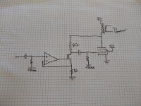
I happened to have a pair of Edcor 5k:8 SE transformers and a pile of used 6384 tubes, so I decided they would go together to form the basis for the amp. I've had good results with 30% shunt feedback in a push-pull amp I built and I recently read an old article about an amp with a first stage transconductance amp (V-to-I converter) implemented with an op-amp and transistor that drives an output stage with a plate-to-grid feedback resistor for 100% feedback. Results presented in the article were impressive.
I figured this fairly simple arrangement would offer a lot to teach my daughter and could be built and measured in the remaining time of the school year.
Then after that, I could work on replacing the op-amp/transistor stage with some different tube circuits I have been kicking around for the V-to-I converter and measure performance differences from the solid-state circuit.
I think this approach has the potential to be a super-performer and be fairly simple. I suspect that the transformer will be the dominant source of distortion in the amp.
Anyway, I plan on chronicling the design and testing here for those interested in this approach.
Attachments
This is current sense and converted into a voltage in series with the input. but it as is have no sense. the main amplifier (The tube) is outside the loop, then no distortion or gain is corrected. And also as is, the circuit only decreases the gain, and increases fet's output impedance, almost always an undesired option. With the fully respectful to you, in my comment, the circuit is almost useless.
This is current sense and converted into a voltage in series with the input. but it as is have no sense. the main amplifier (The tube) is outside the loop, then no distortion or gain is corrected. And also as is, the circuit only decreases the gain, and increases fet's output impedance, almost always an undesired option. With the fully respectful to you, in my comment, the circuit is almost useless.
Osvaldo, see here for a detailed writeup of the concept, page 856. I just stole the concept for an SE amp.
I saw the above cited reference and:
1) it has no author.
2) the fact that is published in a magazine doesn't warranty any good result.
I saw lots of error in magazines, and in books!.
You can do it and test by yourself, but IMHO there are better ideas to take advantage, depending also on your skill, taste and availability of materials to make it.
In fact, I still opine that this circuits is not too good. A personal opinion only.
Jeff Macaulay. He has been around for a while and has published a number of circuits.I saw the above cited reference and:
1) it has no author.
2) the fact that is published in a magazine doesn't warranty any good result.
I saw lots of error in magazines, and in books!.
This is very true, but often these are still good starting points.
Why not start with a pentode up front (and cathode bias)? This is intended to be class A1 right?
Because this is an educational project for my daughter. This gives the opportunity to teach certain concepts (op-amp, FET, and pentode). If I do two pentodes, I only get to cover pentodes.
You better believe that I'll be substituting a pentode input stage as soon as I get this basic amp built and measured to see what the difference in performance is. I've always been dismayed by the uneven spacing of pentode curves working into steep load lines, so I'm interested to see if performance will take as big a hit as I fear.
I have some other, more sophisticated ideas for the input stage as well. The question is, is any of that needed, or is the output transformer distortion going to dominate anyway? I don't really know.
I did build an experimental source-follower SE amp with these output tranformers that I ran up to ~18W and I was surprised by how much distortion originates in the SE output transformers even at low signal levels.
If you want to get ~20W from a series feed transformer with really low distortion, you'll likely need to spend the big bucks. I have run the 20W Edcors in this same arrangement (but all tube), and 20W is pushing it. I too found that at 18-19W, the iron was running out of steam.
Pentodes with steep load lines aren't so bad, especially if those load lines are resistive.
Pentodes with steep load lines aren't so bad, especially if those load lines are resistive.
Pentodes with steep load lines aren't so bad, especially if those load lines are resistive.
That's what I'm hoping to prove to myself. Or I'm hoping that all of the 2nd harmonic distortion that the OT was generating will be out of phase with the 2nd generated in the input stage (and in the same proportion) and everything will magically cancel. I can dream.
I saw the above cited reference and:
1) it has no author.
2) the fact that is published in a magazine doesn't warranty any good result.
I saw lots of error in magazines, and in books!.
You can do it and test by yourself, but IMHO there are better ideas to take advantage, depending also on your skill, taste and availability of materials to make it.
In fact, I still opine that this circuits is not too good. A personal opinion only.
I mean, it seems pretty straightforward to me. A simple FET/op-amp V-to-I converter driving a standard pentode SE output stage with a feedback resistor. This is basically what all of those plate-to-plate feedback amps are doing, only the V-to-I conversion should be much more ideal than in something like an RH84 amp.
The question I hope to eventually answer is: how ideal does that conversion need to be before it doesn't have much effect on the amplifier performance? Is a standard pentode input stage good enough, or is it worth making something better. This V-to-I converter will be the standard to which others are compared.
Oh, and I want to teach my daughter some things about electronics.
Step 1: Transformers
So the first step was to sit with daughter and watch YouTube videos about transformers and I came up with an exercise for her: determine the turns ratio and impedance ratio of our transformer.
We injected a signal onto the secondary and measured the output on the primary (or did we go the other way, I can't remember) and we measured voltage ratios. We then calculated impedance ratios and got 4.6k:8.
That was a bit of a surprise as this is a 5k:8 transformer. I did a little google searching for the actual turns ratio. Edcor doesn't list one but I did find a thread here on diyAudio which discussed measurements of this very transformer and others reported similar results to mine. It seems that my 5k:8 transformer is a little lower than advertised.
This was useful information for us in the next stage, drawing the load line.
Pentodes are very different from triodes in what its behavior refers. While a triode wants as higher load impedance as you can give him, a pentode need a range of optimal loadlines passing through the knee at the desired screen voltage, also dependent on the control grid bias depending on the maximum input signal to be amplified. The circuit you have try to do this using solid state mixing some property of pentodes and triodes, and thinking in complexity of the power supply, I still say that it is useless.
I adhere at the idea of two pentode stages are a better solution.
I adhere at the idea of two pentode stages are a better solution.
This was useful information for us in the next stage, drawing the load line.
EEVBlog has a good video on opamp basics too.
I adhere at the idea of two pentode stages are a better solution.
Noted. Feedback appreciated. This is a breadboard experiment and only the first step in a line of experiments.
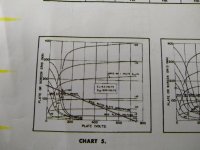
Step 2: Load Line
Attached is the load line my daughter came up with. As you can see, she's going to cook that tube pretty hard. That's okay, I've got a pile of them.
We modified a regulator that now gives just under 400V. We set the screen at ~190V, and hooked up an adjustable bias supply, grid bias resistor, and coupling cap. Then, just for fun, we biased it up to 50mA or so and hooked a phone to it and listened to some quiet music coming from the speaker.
So far, it works like it should.
Next step is the input stage circuit.
ETA: Daughter's calculations indicate 12.93W predicted power output. We'll see how close we can get!
Attached is the load line my daughter came up with. As you can see, she's going to cook that tube pretty hard.
That's okay, I've got a pile of them.We modified a regulator that now gives just under 400V. We set the screen at ~190V, and hooked up an adjustable bias supply, grid bias resistor, and coupling cap. Then, just for fun, we biased it up to 50mA or so and hooked a phone to it and listened to some quiet music coming from the speaker.
So far, it works like it should.
Next step is the input stage circuit.
ETA: Daughter's calculations indicate 12.93W predicted power output. We'll see how close we can get!
Attachments
Last edited:
So the first step was to sit with daughter and watch YouTube videos about transformers and I came up with an exercise for her: determine the turns ratio and impedance ratio of our transformer.
We injected a signal onto the secondary and measured the output on the primary (or did we go the other way, I can't remember) and we measured voltage ratios. We then calculated impedance ratios and got 4.6k:8.
That was a bit of a surprise as this is a 5k:8 transformer. I did a little google searching for the actual turns ratio. Edcor doesn't list one but I did find a thread here on diyAudio which discussed measurements of this very transformer and others reported similar results to mine. It seems that my 5k:8 transformer is a little lower than advertised.
This was useful information for us in the next stage, drawing the load line.
You are forgetting to include the copper resistances of the windings. If you apply 8 ohms on the secondary and measure V/I values on the primary (you can use 110v/60hz in series an amp meter), than you can see the effective primary impedance.
Last edited:
You are forgetting to include the copper resistances of the windings. If you apply 8 ohms on the secondary and measure V/I values on the primary (you can use 110v/60hz in series an amp meter), than you can see the effective primary impedance.
You are correct. If I take the 0.4 Ohm secondary resistance, reflect to the primary, then add the primary resistance to the 4.6 I get 4.9k. However, the forum members who measured this transformer I believe were measuring with large signals and 8-Ohm loads and coming up with 4.7-4.8k.
Any way you slice it, it seems this transformer is a little lower than advertised. I have no issues with that. It's close enough.
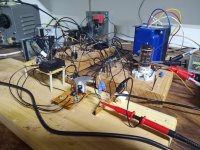
It lives!
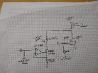
Just got the amp up and running. Attached is a simplified schematic that shows values used.
We've only done listening testing so far, but bass did seem nice and tight and the amp was capable of getting quite loud. I didn't see any obvious signs of clipping on the scope, either.
I did notice that my 6384 tube tends to want to run away a bit as it warms up. I'll probably pull another from the bin and see if I can find a better one.
I got another of my daughters involved in the project now and next I'll teach them how to measure Zout and why low Zout is important.
Attachments
To have a correct bass with modern bass reflex speakers , you need an impedance of less than 0.5 ohms or DF of 16. The shunt tube has according to my calculation has an impedance of 0.625k . This gives for 5k load DF of 8, that is 1ohm . You can add 6db NFB on 499 ohm to check it out.
Last edited:
- Status
- This old topic is closed. If you want to reopen this topic, contact a moderator using the "Report Post" button.
- Home
- Amplifiers
- Tubes / Valves
- Shunt Feedback 6384 SE Amp