Hi,
Please find below the way I managed to connect 2 devices on I2S output/input, using a simple cable.
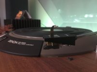
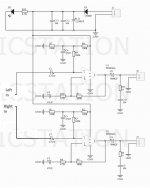
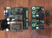
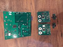
The source is a USB>spdif interface, having a I2S output over a HDMI plug : Gustard U12
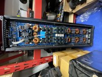
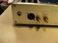
The « receiver » is a FDA (Full digital Amplifier), a QLS-Hifi QA100, having a I2S input over a RJ45 plug.
In my case, the downstream device is a FDA, it could be a DAC of course.
I do not have background in electronics, thus I just made a trial, just by connecting the right pins from each side.
The result is fairly simple : it works perfectly. No hum, no EMI that alters the sound etc.
In my case, the SQ is equal using this I2S cable connection, to a standart toslink link between the Gustar U12 & the QA100.
Thus, no gain in this exemple in using I2S.
But after discussion with others we ends up to the conclusion that it is due to the QA100 that have very good other inputs (toslink, aes, coax, bnc), this makes the difference between these standard inputs & I2S negligeable.
For instance, using I2S on another FDA like I.AM.D V200 makes the SQ much better than coax or toslink inputs.
***************************
These are photos & pics to see what I did :
Wires & color code & pin No in RJ45 & HDMI cable/connectors : basics
Basicaly, as I had no idea about pins in HDMI & RJ45 ports before that job, I just found these info thanks to our mate Google.
HDMI side :
HMDI plug => these are the pins numbers :
HDMI wires inside : 7 simples wires + 4 main foiled cables each made of 3 wires
=> drawing :
=> same info with pins No :
=> cross section cable view :
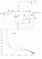
The digital data flow FROM the Gustard U12 HDMI input.
This is the info regarding the pins No & functions on its I2S/HDMI ouput.
It is available on the seller web page.
Of course you need that info to go forward ; I don’t know if these relation pins No vs function is commom to all manafacturers… I would say so. Ask for the manufacturer of your device to be sure.
=> layout :
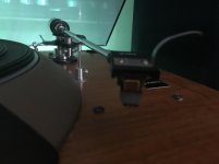
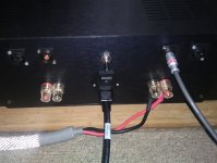
RJ45 side :
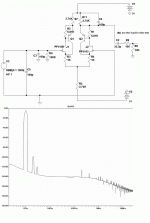
The digital data flow TO the QA100 I2S input over RJ45 plug.
This is the info regarding the pins No & functions on its input :
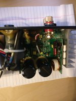
=> simple photo on the QA100, you have all the info =>
RJ45 cables & pins :
1st, I noticed there are 3 types of RJ45 connectors, with the references : EIA-568-A or -B or -C.
These are the differences, it is about a change in the pins No (FYI)
=> 1st type => EIA-568-A & -C
=> 2 type : EIA-568-B
Photo of the RJ45 I used, it is a B type, and the color code you can see through is OK :
Tricky point : on the 2nd RJ45 cable I tested, it was written on its side it was a « C » type, but the wire colors you could see thru the connectors indicated that it was a « B » type, thus I connected it like a B type and it was OK. So, check this.
Which wire on HDMI side corresponds to which wire on RJ45 side ?
Basically, according to the photo of the QA100, the I2S on the RJ45 side requires only 5 wires (
http://img15.hostingpics.net/pics/88250820151119154231.jpg ) :
pin1 = LRCK
pin3 = DATA
pin5 = BCK
pin7 = MCLK
all other pins = ground
On HDMI side, you have, according to this diagram
http://img15.hostingpics.net/pics/644095GustardU12HDMIpinscode.jpg you have more « useful » pins.
For instance, you have a +5V pin, and 4 pairs => DATA+ & DATA -, BCLK+ & BCLK- etc…
So, to make it simple, I thought it is a good idea to let the RJ45 port to lead that connection !
Thus :
I don’t care about +5V pin on the HDMI side, I don’t care either about the DATA- BCLK- etc…
I found nice & straight forward to connect : DATA (on RJ45) to DATA+ (on HDMI) etc… and connect 1 ground pin on the RJ45 to 1 ground pin on the HDMI side.
This is it.
Then I just had to find & connect the wires like described above.
Inside RJ45 & HDMI cable/connectors : wires ID
Inside HDMI cable :
- take off the PVC =>
http://img15.hostingpics.net/pics/75532020151121231715.jpg
nice shield + foil
- open the foil =>
http://img15.hostingpics.net/pics/32240820151121232323textarrow.jpg
you have the 4 groups of 3 wires, as it was showed on this drawing (« + » pin, « -« pin, and ground>
http://img15.hostingpics.net/pics/551890HDMIcablefrontviewPinsNofunctions.jpg
- please note that the color of foils & inside wires does not match the diagram I found, this one :
http://img15.hostingpics.net/pics/740755HDMIcablecolorscode.jpg
thus, the game was to guess > trial > error > trial. 2 small mistakes, but no time lost on this.
Inside RJ45 :
let’s look at a SSTP cable. As said above regarding RJ45, you have 8 pins, corresponding to 4 pairs of 2 cables.
take off the PVC => you found a shield (it is cut on this photo) => inside the 4 pairs, foild => inside this tiny foil, you find a pair.
=>
http://img15.hostingpics.net/pics/60183620151122164714.jpg
According to the pins used in the I2S connection written on the QA100, and the basic data regarding RJ45 plug B type, you realise you need only to deal with the white wires, the other ones will correpond to « ground ».
Usually, each pair is : full color on 1 wire, and color/white on the other wire ; easy to distinguish all these 8 wires.
In my case, in this exemple, no « color/white » wires… they are only white… no a big deal to distinguish & avoid a complete mess between all these full white wires, but really annoying that « color code » seems to be « optional » whatever the cable producer…
Look at the connection :
http://img15.hostingpics.net/pics/42762820151122164803.jpg
the orange wire is on the pin2 => it is a B type cable (although it is written « C type » on the cable…). Thus you know which wire at the cable end correponds to the pin at connector side.
1st connection trial : wire to wire
The 1st test consisted in connecting the 2 cables like this :
Fairly basic & easier to test the right link between pin & cables. For instance, useful when pins No & ID given by the manafacturer of the interface or/and the downstream device are not correct.
I made a mistake and inverted on the HDMI side the wire from the green foil (LRCK in fact) & the silver foil (BCK in fact) : I had some sound, but full of EMI etc…After inversion => dead clear & nice sound.
2nd & final connection trial : RJ45 wires on HDMI connector
The 1st trial allowed to understand the pin/wire links & ID.
Then, to have a ready to use cable, with EMI as low as possoble, I needed to soldier it somehow.
The best way I found was to soldier the RJ45 wires on the HDMI connector.
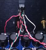
HDMI connector : inside
this is the connector =>
you have some silicone aournd to take off…
then take off the pins you do not need using cutter & clamp.
As seen before, I chose to deal with the pins of the HDMI, only the DATA+, BCLK+, LRCK+ ; MCLK+ (seen here :
http://img15.hostingpics.net/pics/644095GustardU12HDMIpinscode.jpg )
ATTENTION : I kept 1 pin links to the ground.
Because on this photo =>
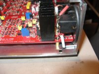
http://img15.hostingpics.net/pics/52331920151122100016.jpg for fun, I cut the ground link => big hum => I wired back 2 ground wire (1 from each cable) => no hum => nice & clear sound
So finally, I have the super nice HDMI connector
side 1 =>
http://img15.hostingpics.net/pics/53591120151122153356.jpg
side 2 =>
http://img15.hostingpics.net/pics/68408520151122153414.jpg ; here the non-green wire is the ground.
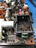
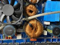
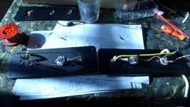
RJ45 cable prepared for soldering.
the RJ45 is fully open, no sheild, foild etc…. Ready to be soldiered on the connector =>
http://img15.hostingpics.net/pics/97436520151122174440.jpg
The trickiest part of the job for a newbie in soldering is ahead…
Note that on this photo you have 2 RJ45 cables.
Why ? because I have 2 QA100 amp. 2 FDA used in passive BI-AMPLICATION for my floorstanding speakers.
The nice thing with this type of cable & I2S connection is that, as mentioned Globulegl on a other thread, there is NO ISSUE regarding impedance voltage etc… too tricky stuff for newbies…
With I2S, just soldier 2 RJ45 cable on 1 HDMI connector, and data will flow without any issue from the HDMI interface to the 2 device downstream on RJ45 port, in sync : perfect solution for spliiting digital audio. Much cheaper than optical splitter of course, & even more cheap than my Mutec MC1.1+ (but the Mutec MC1.1+ can handle inputs… with this cable, you split only the I2S)
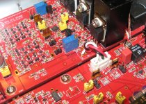
RJ45 cable soldiered on the HDMI connector
side 1 =>
Side 2 =>
So, as you can see :
- the blue wire, alone on the ground pin
- and 2 wires soldiered on each pin, because 2 RJ45 cable for my biamp.
- dots on the white wires, it was to distinguish the color of each pair (given than in that bloody cable, the color/white wires were fully white…)
RJ45 wires & HDMI pins combination
Thus, the combination to link the Gustard U12 to the QA100 is the following :
HDMI connector.
As mentionned above, on RJ45 side we need 4 « active » pins (thus 4 wires) + 1 for the ground.
Thus on the HDMI connector, I kept the following pins : No 1 - 4 - 7 - 10, for the « active wires » ; and the pin 11 to connect the ground.
Reminder, see here the pins No & location on the connector =>
On the HDMI pin 1 (DATA+), you connect the RJ45 pin 3 ; white/green wire of the RJ45 cable type B; or the white one in the foill where you have the green wire.
On the HDMI pin 4 (BCLK+), you connect the RJ45 pin 5 ; white/blue wire of the RJ45 cable type B; or the white one in the foill where you have the blue wire.
On the HDMI pin 7 (LRCK+), you connect the RJ45 pin 1 ; white/orange wire of the RJ45 cable type B; or the white one in the foill where you have the orange wire.
On the HDMI pin 10, you connect the RJ45 pin 7 ; white/brown wire of the RJ45 cable type B; or the white one in the foill where you have the brown wire.
On the HDMI pin 11 (for instance, or another one linked to ground according the Gustard U12 info), you connect a full colored wire of the RJ45 cable, I chose blue…
As you can see on this photo for instance, my soldering is pretty awful, but it works… so why bother with I2S ?...
***********************************************
Sorry if this post is too long and/or not clear. Feel free to ask if you can’t catch a word about this tricky but simple connection.
Hope it helps
Rgds


![IMG_0232[1].jpg](/community/data/attachments/782/782293-9d5b10aa120c539f0fc518ddf6ad1356.jpg?hash=nVsQqhIMU5)
![IMG_0230[1].jpg](/community/data/attachments/782/782326-b3e2533de37ced7b600f9054a55b22b2.jpg?hash=s-JTPeN87X)


