Questions about a Lundahl & a Sterling ST69

Hi there, new DIY guy here. I was hoping to change out the output transformer in my ST69 with a Lundahl. I've done the switches with ribbon mics no problem, and make the assumption switching the output would be fairly easy. Needless to say, I have learned my lesson.


I grabbed a Lundahl LL1940 (it being the "Lundahl Tube Transformer"). I've tried following the pinout guide given by Lundahl, but to no avail. Any help would be appreciated. Just trying to learn here.

FS: Wild Burro Betsy’s and/or Baffles

Hi guys,
I just purchased a brand new pair of Betsy’s with the idea of mating them with some H frame subs, but before doing that I decided to build some baffles similar to those found elsewhere on the web.
I love the Betsy’s and I still plan on building some subs, but in the meantime I have these for sale.
The wood is 7/8” solid oak with a walnut racing stripe. I have the baffles sloping back at 6 degrees. They sound amazing but do taper off at 80hz.
If anyone is interested, $200 plus shipping for the woodwork, or
$300 plus shipping for the whole assembly.
The pair weighs 25lb without packaging, so you can estimate shipping cost from my zip code, 28901.
Stay safe,
Peter

Attachments

  • 7C4D80B6-51C1-4F88-8D2C-DF91262B00E7.jpg
    7C4D80B6-51C1-4F88-8D2C-DF91262B00E7.jpg
    522.9 KB · Views: 342
  • B462859E-BF40-4F04-A03D-BA46270FCBE0.jpg
    B462859E-BF40-4F04-A03D-BA46270FCBE0.jpg
    547.5 KB · Views: 337
  • 7D4AA218-567D-4D07-87DC-7E462D2E2DA8.jpg
    7D4AA218-567D-4D07-87DC-7E462D2E2DA8.jpg
    461.8 KB · Views: 341
  • CED76832-E420-4555-B4DD-02EB5C04CDBB.jpeg
    CED76832-E420-4555-B4DD-02EB5C04CDBB.jpeg
    907.4 KB · Views: 356

Really tight octal socket

I got myself some of these sockets. They look nice and high quality, I was hoping for them to be better than the usual cheap loose wobbly kind.

It turns out they are on the other extreme. I only have 2 types of octal tubes, a Sovtek 5AR4, and a pair of Guiguang KT88. I can get the 5AR4 to sit all the way in, but I need tool to remove it afterwards. The Chinese KT88 I can't even get them all the way in.

I was hoping to to remove the nuts on the pin to loosen the jaw. I tried with a small plier but it won't do. I don't have (and never seen) a wrench that tiny

Any tips to loosen them up? I was pushing the tubes in and out but I think I will eventually break something.

Anyone have experience with them? Will they eventually loosen up? Or am I better off with the cheap wobbly kind?

Attachments

  • 1.jpg
    1.jpg
    125.5 KB · Views: 310

Point source omnidirectional speaker.

I’m fairly new at speaker building and shy away from many traditional designs looking for something different to work on.

I have found a liking for omnidirectional speakers. After make my first I realise the 6 speakers caused an amount of lobing that I seek to try to eliminate.

I researched what is available on Apples HomePod and they seem to use 7 drivers for mid/highs without noticeable lobing effect.

I am working on a larger beast with 12 inch subwoofer down facing and 16 mini speakers using load folded horn design as shown in the picture. Dsp will flatten the speaker freq response.

What should I be looking out for to get the best omnidirectional point source response? Appreciate your experience and comments.

Cheers
Tony

a27d24_d2c984bf1bfc459a919ebb5b9c499af7~mv2.png

FH3 - Best Alpair 7.3 alternative?

Hey,

I am based in UK and very keen to build myself a pair of FH3s. Unfortunately the Alpair 7.3 isn't available anymore over here.

Anyone have any views on what would be the best alternative out of the Alpair 7 MS and the Pluvia 7.2 HD? Or any others worth considering? I've not been able to find much about these newer options specifically considering the Frugalhorn 3.

Best regards

gmarsh Weiner TPA3118 Stereo Amp and Weiner PBTL Mono Amps

D5B78032-73F3-42A9-B72C-96264A0F43AC.jpeg
6114C303-31B6-43C7-99C4-5124C39F823E.jpeg
56F29F2C-8794-45D9-9D8F-BE545A2B2381.jpeg
E4341ED3-865B-4B42-A863-C4201CD00CCD.jpeg

gmarsh-built Weiner TPA3118 stereo amplifier
Complete amplifier with two Cinemag CMLI-15/15B2 input transformers...$120

—————————————- OR ——————————————

Weiner TPA3118 stereo amplifier module only.........................................$40

gmarsh-built Weiner TPA3118 PBTL mono amplifiers, pair.........................$80

Upgraded Astron RS-12A 120VAC/12-13.8VDC power supply....................$50

Will only accept PayPal payments. Will waive PayPal fees. Does not include shipping via USPS Priority Mail to continental US.

Selling these lure at-sounding Texas Instruments Class D amps, because I have too much audio gear.

Is this circuit a capacitor multiplier a regulator or neither?

I found a project article that promises to reduce ripple greatly at a fraction of the heat dissipation of a regulator. The author sets this up for low voltage supply. I have a few questions... Is this a regulator or some type of capacitor multiplier, or neither? Also what mosfet would I use if I wanted to scale this circuit up to handle B+ level voltages? It looks promising to me as a preamp DC filament supply as it wouldn't dissipate as much as a regulator and regulating filaments isn't really critical anyway. For B+ it looks like a simpler alternative to full out regulation, a middle ground between unregulated and regulated?

An Alternative to Linear Regulators: Equivalent Power-Line Ripple Rejection with Less Power Dissipation | audioXpress


Thanks

Novice help putting together a preamp

I have lurked here for a long time and am posting for the first time. I hope you don't mind entertaining some very rudimentary questions. I have built lots of speakers over the years and a few electronics, both tube and solid state, from kits, but it has been a while. I have no EE background but I can solder and read a schematic and work on a circuit without going to the ER. I am working on educating myself on tube circuits, including reading Kevin O'Connor's book. I am hoping to build a preamp/phono from some off-the-shelf circuits I have already. I have both the preamp boards from Ken Stapleton. He specifies that the linestage requires 285/265/6.3 and the phonostage requires 285/245/6.3. I spoke with him fairly extensively over email (super nice guy, BTW) and he says for the 245 and 265 you can meet somewhere in the middle to power everything with one power supply.

I also have the tube rectifier power supply kit from John Broskie. I am not dead set on using this power supply, but I have it and it is much more approachable to me than building one from scratch. I'll attach his schematic below, but it is not my intellectual property to please let me know if that is against rules or etiquette. I am wondering if someone could please point me in the right direction of figuring out if this power supply would be appropriate and what transformer values I would need to get it there. I would like to use dc for the heaters, and I am very confused about how he is handling that since he shows considerably higher voltage for the heaters. Additionally, I'd like to know what to look for in a choke to use, but if appropriate that can be another thread. I still have some reading to do on that front.

Thanks, guys.

ps-tube-9.gif

Final 0.4 mkIII help needed

I have just come into possession of these speakers. I'm hoping to bring them back to there former glory, no sound from the panels. Can anyone help out the specification of these speakers, panel range, cross over point.

So far, I've obtained suitable power supplies to charge the panels, discovered blow fuses (T800mAL) which will be replaced in the next step on the path to discovering there sound. I believe the quad 606 power amp I have will be adequate to drive them.

Behringer Ultrabass BX1200

Hi all....

I have a BX1200 I'm troubleshooting and for some reason the person before me has removed the input jacks plus assocuated connector/cabling. I was wondering if anyone has a photo from the inside to see where they connect to and/or a service manual for these amps... I have found schematics and user manuals but not much else....

Thanks in advance and good to return to the forums.

Chris

Surround speakers: mono/di/bi/tripolar?

Perhaps because this forum is mostly dedicated to 2-channel audio there has not been much discussion about designs for surround speakers. The easiest choice of course is direct-radiating speakers to match the mains, but I'm interested in exploring alternatives because of the tendency to localize the ambient sounds to the surround speakers. An old solution is to roll off the HF but I think this is not applicable when we speak of discrete surround formats (5.1,6.1,7.1 channel).

An externally hosted image should be here but it was not working when we last tested it.


Perusing the home theater discussion groups it seems that there is a lot of appreciation for dipole loudspeakers which, unlike dipole mains, place the listener in the dipole null. The rationale is that for the more localizable higher frequencies, most of the sound reaching the listener will be reflected, giving a larger sense of space. Some of these designs are also switchable to bipole mode, which supposedly sounds better with (most?) multichannel music formats.

The best shoot-out I've found online is the link below; it is an interesting article but the test methodology is a bit bizzare and renders the conclusions a bit suspect in my mind.
http://www.hometheatermag.com/loudspeakers/25/index.html

To throw more fuel on the fire, there seems to be little agreement in the marketplace on how to arrange the "bipole" drivers--there are a host of designs which place the drivers at less than 90 degrees with respect to the lister. I am guessing this is a hedge--less null, but still less directional than a direct radiator.

There are also newer "tripole" speakers which are basically a direct radiator mated with a bipole, with the direct radiator covering some of the lower bass (probably to avoid bipole canceling) but also featuring a direct-radiating tweeter. I suspect, both in theory and from looking at the FR plots in tripole mode versus direct mode, that these speakers are a real mess in the HF due to interactions from the dipoles, reflections, and the direct tweeter. But maybe the monopole bass driver is a good idea.
http://www.hometheaterhifi.com/volume_7_3/m&k-surround-55-tripole-speakers-7-2000.html

I intend to experiment with some of these configurations but I certainly don't have the desire to build two (or more) of everything. The designs which look most appealing to me are the basic or angled dipole as well as dipole mated with a monopole woofer (<100, 150Hz?)--a hedge perhaps between dipole and tripole.

Any thoughts from the forum? I've seen some theoretical comments by planet10 in favor of angled bipole for this application, but I've also seen the sentiment expressed that bipole speakers have no place in discrete surround sound--for those who have tried some of these setups, what did you think?

Bipolar capacitor/s

Good day gents,
I’m in search of a couple bipolar capacitors - 33uf 200v.
I’ve searched the inter web to no avail.

Couple of questions, the caps are being used on the secondary side of the power supply of a crossfire amplifier, in conjunction with the standard rail caps.

Has anyone tried making these before? (Two caps wired in series)
Any reliability issues with this method if done before?

TASCAM CD-601 troubles.

TASCAM CD-601 troubles.

Well, you know me, I always searching for trouble.
Now I found it.
I bought a TASCAM CD-601, because I don't have a CD player, other than some PC drive.
When I bought it, I tried this. It was far from perfect, only some signs of life.
This was spinning the CD, what I put in it, but wasn't play it.
So I thought, that infamous Sony KSS151A laser isn't totally dead.
Therefore I was bargained in a bit and I bought it.
I took it home.
And here began my well deserved (perhaps demanded by myself) Stations of the Cross.
What can I do with it?
I was checked powersupply electrolitics with my ESR meter, they seems to be good, despite of 23 years what they have.
I was found this site:
Laserology
So I was cleaning the laser unit.
And voilá, this began to play CDs.
But what is this crackling sound?
So it wasn't a full success.

But I now use to play CDs this equipment about some months.
If somebody interested in, I will tell you the solution, and how I find it.

Regards,

Gyuri

Luxman PD 131S Turntable - Strobe light -HELP

Hi all,
I have a Luxman PD131S TT and the strobe light is not working.

The only service manual I can find is this:
https://www.vintageshifi.com/repertoire-pdf/pdf/telecharge.php?pdf=Luxman-PD-131-Service-Manual.pdf
which only refers to the 121 and 131.

I thought there would be enough similarities between the 131 and 131S, however if you look at my photos of the strobe PCB below, the numbering of components is different.

Can anyone help to identify which capacitor I should look at replacing in this circuit? So far, I have removed the C402 which is a 330uF, the smaller cap close to the fuses is a 2.2uF. The fuse F401 (100mA) was blown as well, which, after reading another repair forum on the PD121, led me to suspect a capacitor. I don't have a circuit diagram to work it out.

Attached are pictures of my board with caps, fuse and strobe encircled as well as a screen shot of the PD121/131 circuit (which is not a direct match to my board).

Thanks!

Noob here

Just saying hi, I was an intermittent lurker, will still lurk but no longer mute.

I live a stone's throw (almost literally) from O'Hare Airport Outside of Chicago, and have a strong interest in the Silver Pioneers, having started out as a dealer repair tech in the late 70's.

I can usually be found slaving away on the Audiokarma Pioneer Audio Forum, under the same handle, enacting virtual stooges routines with various folks as we strive to get their Silver Pioneer equipment singing.

My avatar was awarded to me by EchoWars after a particularly harrowing time in a thread, as opposed to being a stooges fanatic.

mark

Service manual for Counterpoint NPS 200

I own a Counterpoint NPS 200E power amplifier. Unfortunately the power transfer fried recently due to an unknown reason. The amp was at standby and I was out from home..

Now I need to have it repaired and for this I need a copy of the service manual. Michael Elliot is long disappeared and altavistaaudio is not operational anymore. My only hope is you..

I desperately need any of the followings:

1. A copy of the service manual for Counterpoint NPS200E.. I am ready to pay a reasonable price for this

2. The values for the fried mains transformer..

3. An information regarding where I can supply a replacement transformer

As said before you guys are my only hope.. I need your help..

Best regards..

Eminence Alpha OB question

With time on my hand I am dusting off some old projects.

Like my Eminence OB project. I'm using a Eminence Beta 12LTA plus tweeter and two Eminence Alpha 15A per side. And will be using two Icepower 125ASX2 amplifiers

I know this I done many many times and still I have question. In his paper MJK uses a 9mh coil and 68uf cap for the one Alpha, I am using two, so I searched for filter solution but almost everyone uses an active crossover or MiniDSP which I don't have.
Has some of you got an (cheap...) idea for a passive crossover?

Ps, I do have a third amplifier if necessary....

Raymond

stepped attenuator question

Hi
Here I have a simple question regarding stepped attn.:
I am thinking about building a balance-pot as a stepped attenuator, probably ladder style.

Center-Position would be both channels fully open, a turn to the left attenuates the right channel, a turn to the right attenuates the left channel. The other channel is left untouched.

I could then just install a bridge along the remaining positions (right half of the left channel and left half of the right channel), right? (thus requiring half as much resistors)

thanks!
david

Soundstream 4.920 schematic

Anyone got schematics for this amp?
All the schematics I have, have the 3525 power supply chip.

It’s a bit hard tracing with the silk screen and then the bus bars over the smd components.
I got 8.92vdc occasionally on pin 16, sending the amp into protect and I’m trying to trace through the circuit.

Attachments

  • 83D8C03E-6718-42D4-95DC-6E677F2A8A71.jpg
    83D8C03E-6718-42D4-95DC-6E677F2A8A71.jpg
    1 MB · Views: 242

Type of Pot Needed

I had an headphone audio in jack that wasn’t secure/connecting all the time so opened up this old 90s amplified 2.1 speaker trio and super glued it down, but in the process broke the subwoofer level pot.

From this pic, anybody have a guess at what specs/size of replacement pot to get?

UPDATE 8-9-20 - Looks like pot is 6mm width on knurled dial post and 15mm long (or about 1/4 in. and 5/8 in. respectively) and (based on comments) its a 50K linear pot. Pics of caliper readings below. Any suggestions as to specs for # of gangs, wattage and whether linear, audio or reverse audio is best would be appreciated. Thanks for all the input already, very helpful for this tinkerer!

There are mindnumbing levels of options for this pot on mouser: Bourns 50 kOhms 1 Turn 15 mm Potentiometers | Mouser

A2176-B45-FA9-C-42-CB-84-D0-1-AECAF6-D98-E7.jpg

Dial-post-Caliper.jpg
Peg-Width-Caliper.jpg

Build Dick Olsher's Design with Sal08C08

I have all the parts to build Dick Olsher's Visaton Nobox, but my new house I will be moving to does not have enough room for the speakers. I am selling all the parts I acquired for the build.

- 2 Brand new and never used Sal08C08 woofers - $900 Value
- 2 Brand new and never used Augie Hawthorne 15 inch woofers - $250 Value
- 2 Brand new Erse 3.0mh 16 AWG inductor - $44 Value
- 2 Brand new Erse 5.0mh 16 AWG inductor - $50 Value
- 2 Used but low hours Solen 33uf caps - $30 Value
- 2 Used but low hours Audyn 33uf Caps - $20 Value

All you need is two nice 10uf Polypropolyne caps to get to 76uf, build the crossover, then build the Visaton NO Box design.

This is a $1300 value and I am asking $1000 SHIPPED CONUS only.

Below is a link to Dick Olsher's page..

Tip_85

Hafler matrixed surround sound circuit with a PAss 250.8?

Does anyone (or NP if he sees this) if I can try a simple Hafler Matrix surround speaker set up tied onto my Pass 250.8?

The circuit would tie a rear pair of speakers on the amp, positive Right out to positive in -rear speaker- negative from same rear speaker tied to negative on other rear speaker and positive on the second rear speaker going back to the Left Positive speaker out on the amp- essentially running a series path out of the Right amp speaker thru the two rears and back to the Left positive speaker tap on the amp? Can I experiment with various resistors in the 10k ohm range to attenuate volume in the rears?

I know Pass amps have a different set up on amp outputs than most amps ...thanks

Simple schematic attached...

Attachments

  • hafler.jpg
    hafler.jpg
    71.5 KB · Views: 167

slp-90 clone, decent preamp!

Got mine built tonight, my aikido octal/6sn7gt is a little darker then this slp-90 clone from fleabay, all in all im enjoying it, nice and quiet!


An externally hosted image should be here but it was not working when we last tested it.


Like it better with telefunkens thrown into the mix.

An externally hosted image should be here but it was not working when we last tested it.

Does anyone have specs for the Anarchy-558?

Hello,

Looking for information on the Anarchy-558,

- T/S Specs
- Frequency response graph
- Physical dimensions

I emailed the company two years ago asking for this info, and their response was that it going to be posted "soon". I emailed again recently and received a similar answer.

This begs the question, why try so hard to buy something the company does not seem interested in selling. Good Point. But the 7xx series are well reviewed and I would like a similar 5'ish woofer in that price range.

Anyone?

Thank you,

David.

Old Microphone Question

Good evening all,,, I wasn't sure exactly where to post this, but this cool mic came with an old Webster Electronics amp, & look what I see when I open the capsule,,, diaphragm & internals seems to be all there, but the 2 wires coming from the small tranny, are disconnected from the 2 solder joints at that wafer beneath the magnet. How would I determine which wire goes where? I s'pose one way would be is to wire it & see if it's OOP with another known 'correct' mic,,, but is there any other telltale sign from before my time?
Thanks all & be well
Kenny

Attachments

  • 20200825_203858.jpg
    20200825_203858.jpg
    970.4 KB · Views: 184
  • 20200825_203816.jpg
    20200825_203816.jpg
    1,022.7 KB · Views: 149

Super LM3886 parallel 4 chip

I found this scheme on the net and tried to carry out the project with 4 LM3886 chips, the result obtained is very pleasant, the pcb groups the two amplifier stages and two psu. The sound is very different from that obtained from the single Lm3386, with this stage you can see better driving at low frequencies and excellent transparency on medium-high frequencies.
pcb also accept an antibum-protection.
if interest pcb is available in 3pz...with BOM
thanks

Attachments

  • 87219987_605124503677170_1938833449565552640_n.jpg
    87219987_605124503677170_1938833449565552640_n.jpg
    419.5 KB · Views: 1,633
  • 86697042_505342670394898_13001626214203392_n.jpg
    86697042_505342670394898_13001626214203392_n.jpg
    470.1 KB · Views: 1,087
  • 86698376_510034332988616_3777811731292618752_n.jpg
    86698376_510034332988616_3777811731292618752_n.jpg
    261.1 KB · Views: 1,026
  • 86773239_199262211440114_203317850507575296_n.jpg
    86773239_199262211440114_203317850507575296_n.jpg
    310.8 KB · Views: 1,017
  • 86857585_1136297526712480_6188813845063008256_n.jpg
    86857585_1136297526712480_6188813845063008256_n.jpg
    402.2 KB · Views: 1,172
  • pa150_schematic.jpg
    pa150_schematic.jpg
    145.9 KB · Views: 1,002

Need to pick a speaker-head's vibrating brain please!

hi guys i'm new here and i don't know what to do???? actually, i kind of have an idea, which may make it even worse - but anyway - i would like to build a studio monitor speaker. i have a Kenwood Power Transformer L07-3240-15 and most of a kenwood receiver to work with. i also have the speaker. i'm not concerned about the aesthetics or overall design, what i need help with is the circuit. Please, if you know of any good links or perhaps articles short of a home electronics course i would really appreciate the help. thank you

Vinyl 'Wrapping' Cabinets for Reclaimed Wood Look

Hello,

I've finished my first set of Jeff Bagby's Continuum II speakers! Wow, I am blown away by the sound. Here is a picture of one of the Continuums. Unfortunately, it acquired a dimple in the front baffle due to hangar bolt issues... nevermind that for now, I'll have to fix it. (first time)

I don't like the way the paint turned out. I sprayed them with a higher performance version of plasti-dip which must be sprayed our of an HVLP gun, 1.8mm tip, all that stuff. It's not bad, but it's not what I wanted. It marks too easily and honestly, it doesn't take much for the edges to peel. It's not low maintenance at all.

So before I go out and buy some automotive urethane and respray them, I wanted to try wrapping them in vinyl to get a reclaimed/weathered wood look! I bought some architectural vinyl by 'vvivid'. I saw pictures of people wrapping their kitchen cabinets in it, so I figured 'why not a speaker cabinet?'

I opened the package and it isn't extremely flexible at all, and this worries me. I would say it's more like wallpaper than any kid of wrapping material. For perfectly square boxes (or cabinets), I'm sure it's no problem. However, I used a router to give my boxes smooth edges all the way around, including rounded corners. I'd need to almost 'melt' the vinyl to get it to adhere to the shape of the corner I imagine. Even worse, the woofer is recessed a half inch or so with a nice, rounded edge all the way around. I'm not sure how the vinyl is going to confirm to that, unless it gets VERY 'mold-able' when heated.

There is some (much) more expensive wood-like vinyl by 3m called 'di-noc', which appears to be very malleable, but I feel like I may be S.O.L. either way with the recessed baffle shape. I really want to give these a weathered, whitewashed wood-look. My wife is actually excited about the idea of them, and that's saying lot when it comes to my speakers, ha ha!

Any suggestions? Maybe I there is some other way to get this look on MDF cabinets that I don't know about. I really appreciate it folks. Take care.

P.S. Here is a picture of the reclaimed/weathered look I am going for:

Attachments

  • Continuum-IIs.jpg
    Continuum-IIs.jpg
    100.7 KB · Views: 452
  • reclaimed-white-wood.png
    reclaimed-white-wood.png
    692.4 KB · Views: 333

Transistor cross-references?

Its been a long time, about 5+ years or so since the last time I repaired a car audio amplifier.

So, Starting to pick some of that up again, and unfortunately, I have lost my sheets and reference charts ive built up over time for some of the transistors that I got from digikey. Not to mention, the email address and password to the old digikey account I had so thats gone too since it was at another work place.

Anyways, Working on a couple JL Amplifiers, and I cant remember what digikey or mouser cross-references were good for the power supply driver transistors marked UY and WY, As well as the C3207/A1070 transistors.

the IRF540s are shorted in one of the 4 channels, and with those removed, there are a couple LEDs on the driver card that wont light up either without the transistors in circuit. I cannot remember if this is normal or not, its been awhile. But I digress.

any ideas? Thanks.

HiFiBerry DIGI+ I/O problems with Raspberry OS, kernel 5.4

As part of an audio project I want to record digital audio (spdif via toslink) on an R-Pi 4B and am exploring options for an interface with digital toslink input. I have gotten everything working with a miniDSP USBStreamer, however, at half the price I thought I would also try HiFiBery's digi+ I/O board. Unfortunately it doesn't seem to function (at all). Communication with Danial at HiFiBerry has not resulted in a solution (he is not sure why it does not work properly). Details below.

I can attach the digi+ I/O HAT and set it up in the OS so that it is recognized properly. I can probe the hw-params using arecord. To try and record audio, I connected a CD player's toslink output (the same one I successfully used with the miniDSP unit) and attempted to use arecord like this:
arecord -D hw:CARD=USBStreamer,DEV=0 -c 2 -f S16_LE -r 44100 ~/test.wav
The command executes and then after about 10 seconds or so it self-terminates with a message about an I/O problem. A file called test.wav appears but it in only 44 Bytes in size (probably only contains the header). During this 10 seconds, I can look at the file
/proc/asound/USBStreamer/pcm0c/sub0/status
The status file shows the PID using the card, as well as info about the memory pointers involved in reading the data from the soundcard and creating the file. The pointers all remain at zero, and all other values stay the same. Also, looking at running processes via top the arecord process does not appear. This tells me that the process is halted or asleep, or blocked.

In fact, on the HiFiBerry web site there is a note that for kernels 5.4 and above they are having some issues:
Configuring Linux 4.x or higher | HiFiBerry
Scroll down about halfway in the note to get to the relevant section. I followed the advice given there but have not been able to prevent the blocking behavior.

I also used a toslink to coax spdif converter and tried to feed the digital output from the CD player into the coax input on the HAT, but the behavior was unchanged.

Has anyone gotten this card to work with a recent kernel like 5.4 or higher? Any ideas on what to check, or modify that might fix the problem?

4 ch power distributor design- needs the relays replaced?

Hi I have only been able to making this "power" distributor by using relays, but there are no reason for using relays at all, any other solution would be great! Maybe using some BJT's?


In the schematic can you see what I am trying to do:
There are 4 push buttons that lead power to a 3TSP, when that pushbutton is pressed, do the relay latches and connect the Selector power and turn a LED on.
Above the pushbutton are there some other relays to "de-latch" all the other relays.
On the first relay, by the first push button are there a capacitor, to always turn on ch 1 if the unit has been turned off.


I have made a simulation of the circuit and hope you can please tell me, how I can get rid of K1 by using something else, preferable a small THT component, like a BJT.


http://tinyurl.com/y4ntq52n

Attachments

  • Udklip.PNG
    Udklip.PNG
    109 KB · Views: 83

  • Locked
Can somebody delete my Topic?

I didn't see any place where i can contact a moderator and every time i get here i just have to scrool down countless pages to find an available online moderator.

I'd like a topic deleted by a moderator cause i'm going to launch another one on the same subjects as the previous one had no reply anyway and the new one will be a bit better.
https://www.diyaudio.com/forums/analogue-source/358473-mm-phono-preamp-headphones-amp.html
Thank you!

Schaeffer Front Panel Designer

Started to explore the "Front Panel Designer" software from Schaeffer and although the program is reasonably intuitive,
I cannot figure out how to change the colour of the "Create Scale" part other than black. When engraving Text there is a wide range of colour to choose from, but that is not the case with Scale. Did I overlook something? Does anybody on this forum has some experience with this software anyway?
MODERATOR : Feel free to move my thread to the right place on this form!

Feedback loop influence on DC biasing

Hi guys,

I am studying the three stage amp topology. I understand why the voltages are set the way they are when there is no feedback loop.
However, I would like to understand why introducing the feedback sets the VAS's collector voltage somewhat below 0 as we need it to be instead of close to the negative rail.

This is Bob Cordell's circuit which I modeled to better visualize it.

I appreciate your help,
thank you

Attachments

  • with f.png
    with f.png
    89.6 KB · Views: 100
  • without f.png
    without f.png
    89.6 KB · Views: 103

Theory check rule of thumbs loudness

My theory is rusty and old.
The following is correct right?

10^3 Watt (1kW) = +3x10dB (or 3Bell) = 2^3 or 8 times perceived loudness?
Same 100 watt equals 4 times perceived loudness?
10^n watt equals 2^n loudness, where n is bell and bell is defined as one perceived doubling.

How simpler things would have been if I realized this many years ago. I have wasted time thinking about 2x effect = +3dB but even if correct it has no practical purpose.

It’s like discovering the golden ratio by accident.

DON'T ASK phono and headphones amplifier with equalization

6 weeks of work in total and the last embodiment of the phono and headphones schematic.
I use that black relay to link the input and output of the lh0002 buffers of the headphones amplifier when i'm using lighter (250 ohms ) headphones.
The distortions with the buffer working in the feedback loop aren't great .They are around -66db for h3 at 5khz(no even distortions...not that good) and -77db h2 at 1khz on 32 ohms, but with lm6172 with both outputs of a chip in parallel i can go safely with 32 ohms cans and extremely low distortions.
The buffers might be useless but LH0002 military version isn't exactly the bc337/327 buffer i used in simulations so i just hope that the reality will sound a bit better 🙂

The rest of those kits are just a high power voltage multiplier, +-20v and +-10.8v regulators, virtual ground generator, phono preamplifier, and split ac ground capacitor bank for the headphones outputs.Yes...i have two of them with two different capacitor banks.
The headphones amp offset might be a problem with the actual composition but that remains to be checked.The op-amps in the headph amp aren't placed in the photo as there is no clear choice for the final class AA amp.Probaly opa2132 and lm6172 will fit the bill.
The phono preamp is just aiwa c-22 on steroids.The schematic and asc file will be available soon.

Attachments

  • IMG_5137.jpg
    IMG_5137.jpg
    1,011.1 KB · Views: 371
  • IMG_5138.jpg
    IMG_5138.jpg
    1,013.7 KB · Views: 319
  • IMG_5144.jpg
    IMG_5144.jpg
    1 MB · Views: 312
  • IMG_5145.jpg
    IMG_5145.jpg
    995.4 KB · Views: 293
  • IMG_5148.jpg
    IMG_5148.jpg
    981.6 KB · Views: 289
  • IMG_5149.jpg
    IMG_5149.jpg
    997.4 KB · Views: 158
  • IMG_5150.jpg
    IMG_5150.jpg
    987.3 KB · Views: 157
  • IMG_5151.jpg
    IMG_5151.jpg
    1,021.2 KB · Views: 213
  • kenwoodx7original.asc
    kenwoodx7original.asc
    9.6 KB · Views: 83
  • head.png
    head.png
    61.7 KB · Views: 312

Ale Moglia BARTOLA Gyrator 08 board pair

For sale pair of superb Ale Gyrator boards with verry good parts.Used but in top shape.Im using now output transformer so dont need this anymore.I payed 160 pounds plus shipping for pair,it was total around 220 euro.I put bether capacitor Miflex copper foil and some better grid stopper Takman Carbon.Price is 120 euro plus 6,90 shipping iside Europe.For offer plese contact me.

Attachments

  • 20200823_125223.jpg
    20200823_125223.jpg
    1.1 MB · Views: 433
  • 20200823_125228.jpg
    20200823_125228.jpg
    1,019.3 KB · Views: 396
  • 20200823_125232.jpg
    20200823_125232.jpg
    1 MB · Views: 381

How good is Vifa D27TG-35-6

Both Falcon and Willslow recommend the VifaD27TG-35-6 as a KEF T-27 substitue on their website.

http://www.falconacoustics.co.uk/dr...eters-drive-units/vifa-d27tg3506-tweeter.html

Vifa D27TG-35-06

The KEF T-27 is getting too expensive for DIY project while I can get the Vifa in the US at reasonable cost. How good is this Vifa.

I understand that it is not identical to the KEF electrically and will require crossover update. With the right simulation program such as Jeff Bagby's PCD, the crossover update should not be too difficult.

Thoughts on the Solstice MLTL?

I have the itch to build some speakers, having recently been liberated from the confines of desktop/nearfield placement. I'd like to build some modestly-sized floorstanders.

So I've been looking for an already-designed "higher end" kit, and came across Jeff Bagby's Solstice MLTL. The kit price seems to be a pretty good value (given the cost of the raw drivers). The flat pack kit is a huge plus for me too. And the designer's reputation speaks for itself.

Just wondering if anyone here has any experience with them, and or any thoughts on them in general? One thing I'm particularly curious about is the high frequency roll-off above 10kHz. I certainly don't claim any expertise, but most of the speaker frequency response graphs generally seem pretty flat up to 20kHz. Despite that, it seems all the impressions I've read about these speakers are overwhelmingly positive.

Impedance curves

hello everybody!
if you wouldn't mind, I really need some/your help, please. I am trying to trace the impedance curves for Eminence Beta 12A and Fane Sovereign 12-300 but, no matter which software I've been using, (vituixcad, spltrace and another one whose name i can't recall now) couldn't get it right. could anybody help me, please?
thank you in advance

Attachments

  • Eminence Beta12a-2.png
    Eminence Beta12a-2.png
    942.5 KB · Views: 202
  • fane 10-300.png
    fane 10-300.png
    175.4 KB · Views: 222

Best practice to protect OPT against accidentally pulled LS cable?

Hello,

how do you protect your OPT against open loop secondary ?
Do you put a resistor across the secondary - what would be the minimum current / max. value ?

Or do you use Zener ? Assuming an amplifier with 25W / 8 Ohm (10 Vrms) do you use i.e. 2x max. voltage = 28 V Zener in anti parallel configuration or other value ?

Thank You

NEZ Amplifier (The Yin Yang of ZEN)

This simple single ended amplifier could serve as a complement to the well-known ZEN, both for its extreme simplicity and for its quality specifications.

As features, I can list:

1) SNR at 1W into 8 ohms = 87.71 dB (1 KHz)

2) I bias = 1.45 A

3) Output impedance = 2.23 ohms (1 KHz)

4) Damping factor at 1 KHz and 8 ohms = 3.57

5) Voltage gain at 1KHz = 12.88 dB (x 4.4)

6) PSRR at 100 Hz = 41.33 dB

7) Supply voltage = 32 VCC aprox.

Two adjust: Offset ("O" trimpot) and I bías ("B" trimpot)

attachment.php


attachment.php


attachment.php


attachment.php


attachment.php


attachment.php


Best regards

Attachments

  • NEZ Amplifier (Schematic).jpg
    NEZ Amplifier (Schematic).jpg
    152.3 KB · Views: 1,171
  • NEZ Amplifier (THD vs Output Power).jpg
    NEZ Amplifier (THD vs Output Power).jpg
    133.6 KB · Views: 1,110
  • NEZ Amplifier (THD vs Frecuency) at 2W.jpg
    NEZ Amplifier (THD vs Frecuency) at 2W.jpg
    125 KB · Views: 1,109
  • NEZ Amplifier (THD vs Frecuency) at 1W.jpg
    NEZ Amplifier (THD vs Frecuency) at 1W.jpg
    124.7 KB · Views: 1,097
  • NEZ Amplifier (Bode).jpg
    NEZ Amplifier (Bode).jpg
    731 KB · Views: 1,080
  • NEZ Amplifier (PSRR).jpg
    NEZ Amplifier (PSRR).jpg
    231.7 KB · Views: 1,089

Taramps

After replacing driver ic and PS FETs the transformer is squealing really bad.If I install just one FET per bank there is no squealing.Twist and turn not making a difference.

Signal on the drain when squealing

Attachments

  • 3B337D4B-7471-4064-A76A-E6FFDBD0F6E1.jpeg
    3B337D4B-7471-4064-A76A-E6FFDBD0F6E1.jpeg
    818.8 KB · Views: 167
  • DCE38EAE-19C2-4274-85C6-E133FA1F013A.jpeg
    DCE38EAE-19C2-4274-85C6-E133FA1F013A.jpeg
    502.1 KB · Views: 158

DIY Marble Monitor

Hello fellow DIYers 😀
I proudly present my 100% diy nearfield Monitors.
After nearly 2 years of prototyping, designing and testing they are ready.
My goal was to design more or less cheap active nearfield speakers.
I compared them to Genelec 1029a (which i really like),
and they performed better then expected, they sound awesome. 😀

They are powered by an 50VA 25V torodial transformer, with an added
5V winding for the DSP.
They are bi-amped with two self oscillating class-D Modules,
and controlled by an ADAU1701.
Woofers are 5" Faitalpro 5FE120, amazing and cheap (<30€).
Tweeters are 1.3" soft dome LAVOCE TN131.00 (<15€).
I also added an extra switch, i call it "HIFI mode", which boosts the lows
and the highs. 😎

The front is made of 20mm South-Tyrolean Marble, wood is cherry,
and th br-channels are made of mdf.
Since i got the marble and wood for free the total cost for 1 speaker was
aprox. 80€ (working hours included <5000€ 😉 )

Since i dont have access to an anechoic room, i used the silence outside due
to the corona quarantine here in Italy to measure and adjust the speakers. 😛
The neighbours probably got crazy after 2 hours of sweeps 😀.

Here are some PICs:

attachment.php

attachment.php

attachment.php

attachment.php

attachment.php


The measured frequency response after adjunsting with the DSP:
attachment.php


Maybe i will replace the transformer with a flyback SMPS, and place everything on one PCB...
Lets see 😉

Attachments

  • 1.jpg
    1.jpg
    255.5 KB · Views: 1,265
  • 3.jpg
    3.jpg
    459.2 KB · Views: 175
  • 4.jpg
    4.jpg
    269.8 KB · Views: 1,215
  • 6.jpg
    6.jpg
    196.5 KB · Views: 212
  • 8.jpg
    8.jpg
    483.6 KB · Views: 1,276
  • 9.jpg
    9.jpg
    294.1 KB · Views: 1,471
  • 11.png
    11.png
    58.3 KB · Views: 1,260
  • 12.png
    12.png
    83 KB · Views: 223
  • 7.jpg
    7.jpg
    382 KB · Views: 1,753

Full bridge in-phase switching at idle ol

Just thinking about if you had a full bridge class D and under no signal conditions, instead of each side switching up and down at 50% duty cycle but without reference to the other side, how would it be if both sides of the bridge were synced so that they both went up and down at the same time. For the signal to swing one direction the left side gets wider pulses and the right side narrower pulses, and vice versa for the opposite polarity output signal, but both PWMs centred on the same point. The upshot of all this is 1/ the output inductor would run way cooler because it would see a PWM level that is proportional to the audio level, not get hammered full blast even at no signal. 2/ the output HF ripple would be proportional to the audio signal level I think. One downside is there would be LOTS of common mode switching noise on the speaker leads that would have to be dealt with somehow.

Are there any amps that use this technique?

Do As Papa (and others) Do

This is a thread dedicated to the generosity (in every way shape and form) that I want to recognize and thank Pa and others on this forum for.

I have benefited countless times over the last decade from their knowledge and guidance as well as been the recipient of gifts at BAF.

I suppose the simplest way to put it is that these people inspire me to “Pay It Forward”.

Waiting for a possible opportunity to travel to another BAF didn’t seem realistic since I live at the other end of the country.

So instead, I made a donation to DIYAudio and decided to give something away in the spirit of the BAF raffle.

Pictured below is a PASS B1 kit that I purchased a few years ago.

There is a yellow folded Post It next to it in the picture.

I have written a number between 1 and 100 on the bottom side of the folded Post It.

SEE POST #7


Any member is eligible to guess the number and win the kit for free.

Each member gets only 1 guess.

UPDATED GREEDY BOY RULES:

In the interest of expiditing the give away and hopefully benefiting the forum you may now play by GREEDY BOY rules. Anyone wanting more than 1 free guess may do so by making a minimum donation to DIYAudio of $10. You get some more forum privileges by doing so, and you also get 1 guess per each dollar that you donate! Anyone interested need only PM some evidence that they have made a donation.

I will pay postage to mail the kit anywhere a US Flat Rate or Priority envelope will take it.

If special mailing beyond Flat Rate/Priority are needed to reach the winners location arrangements to split shipping costs 50/50 will be made.

NOS 6SL7 Pairs (2)

Dug out a few 6SL7 for a wanted ad here, but poster went after a pair of treasured Special Red 5961 instead (I would have too!)

Anyway -

First the pair of RCA - JAN CRC 6SL7GT from 2/54 tested on my Knight 600 (min good is 55)
88/88
86/88

$25 each + ship CONUS

Attachments

  • IMG_0580.jpg
    IMG_0580.jpg
    835.4 KB · Views: 193
  • IMG_0581.jpg
    IMG_0581.jpg
    813.1 KB · Views: 165
  • IMG_0582.jpg
    IMG_0582.jpg
    671.1 KB · Views: 158

Faitalpro 3fe22/25 Scanspeak 8424 comparison

Hi,

I own the Faitalpro 3fe22, however I am curious to try the scanspeak 8424. I know one is called a 3" and the other is 4" but actually they have the similar cone area (30 vs 36 cm^2).

I am looking for someone who has actually own or heard both 'Live' and could comment on the difference in subjective sound quality.

I know there is a thread on comparison of 2-4" drivers but I would take it with a pinch of salt since the listeners heard it through their own earphones.

Thanking all in advance.

Oon

Berning ZH-230 & Meridian 507 cannot control volume

Hello

I recently bought a Berning ZH-230 amd connected it directly to my Meridian 507 CD player using the preamplifier section of a McIntosh MA-5100.

According to my Mac owner's manual, page 11, "The preamplifier output is connected by the input selector switch to the tape output, the tape monitor switch, the balance control, the loudness compensation switch, and the first section of the volume control."

So I hooked up from the tape out RCA's of the Mac to the inputs on the ZH-230.

Turned the speaker switch on the Mac to "off" position and switch to the "tape monitor" position on that rocker switch but I cannot control the volume, it is very loud, no up, no down.

The volume of the Meridian MSR remote allows volume adjustment of preamplifiers or digital loudspeakers but I have no preamp and it does not respond.

Ibanez TBX15R - Broken

HI all.

I've recently pulled my old Guitar amp out of the garage only to find it's dead.

First observations were:

When turned on:
  • No Lights,
  • Slight speaker hum,
  • speaker pops when turning off

Latest Observations:

  • Power plug fuse in working order
  • Measured continuity in both primary and secondary coils of transformer
  • Cant see any obvious faults in soldering etc, circuitry
  • If left on for a minute or two i can smell a slight burning smell - a lot like a hot glue gun smell
  • From inspection it looks as if the two large(physically) resistors in the centre of the chip (see pic) are whats burning the glue around and on them. (i was able to measure an appropriate resistance across these resistors)

I'd love to get this thing working again. Any ideas as to what the problem is or where to look next?
(i am armed with a soldering iron and a multi-meter and an engineering degree)

Cheers,

Chris

Running caps near voltage limit

I got a nice deal on some Panasonic TH-A series caps 63v 27,000uF 105c types .

The question I have is, can I run them at 64.4v rails at idle? The data sheet says surge voltage is 79v. With load the rails drop to 63.5 at Quiescent load and with music etc they drop further.

Getting another Transformer is not my first choice... I am trying to understand what safety margins are built into these caps...

Data-sheet for these caps is here: Access Denied

Ressurection, repair, restoration and modding of a Marantz CD273

So just got hold of a Marantz CD273, very cheap, DOA (wouldn't do anything when switched on). Turned out to be the voltage selector. I decided to take it out completely and hardwire transformer to 240V. Immediately the player was back to life. BUT: it wasn't recognizing the CD.

So, first things first and safety always: made a little movie of the laser with my mobile phone. Argh... NO red dot! But I've heard, read and seen enough related to the infamous blue C2103 33uF Philips cap so I stayed calm and got the soldering iron and exchanged the cap with a fresh normal 33uF radial cap. Hooked it all up and tried again... tada! red dot was there!! 😀

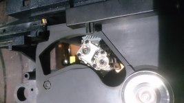
Inserted CD, got TOC a couple of times, other times it failed. Playback was failing at the middle of disc. So, now that laser was back to life it was time to do the usual servicing - cleaned the lens, also the inner lens, was all very dirty. There I had two surprises I didn't have before with any CDM mechanism: the screw on this one has a nut on the other side which always falls out and is a real pain to put back in! The other surprise was a little thin whitish plastic piece that suddenly appeared no my desk as a left over piece when lens case was back assembled together. I didn't like that. And yes, the result was bad: although lens was shiningly clean and laser working fine (I also adjusted laser voltage, was at 65mV, put it back to perfect 50mV), the mechanism was making a weird noise when reading past track 1 and started to fail and skip badly at every CD from the middle onwards. I decided to investigate that little whitish plastic thing. I reopened the lens case again and discovered another of these plastic things beneath the upper half. So I figured the other one would be on top, yes, there was a glue mark, it had simply fallen off due to age! 😱 I got superglue and put a real small drop and glued the plastic thing back to its place. Reassembled (with the nut falling out so many times...) and tested. Incredible, the noise was gone, how's that even possible, that plastic thing can't weigh more than 0,5 g??? I'm not sure if it was the cause, but the problem was gone. Now, player was playing normally most CDs, but failing sometimes suddenly towards end of disc or not reading TOC. Audio was great, btw, even though I haven't changed caps on mainboard yet.

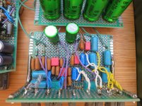
Decided to change remaining electrolytic caps on CDM servo board to new ones. Then noticed that it's an older version of CDM2-board, with the focus potentiometer. So had a look at service manual, states that this has to be adjusted measuring 400mV on a certain test connection (across a cap). I found out that this is a real tough adjustment (I guess they had a special test disc) as the voltage fluctuates! In time and depending on where the track is! So, I ended up doing a lot of trial and error and managed to find a kind of sweet spot, it's not really 400mV, but it fluctuates between 220 and 450mV, depending on disc poisition. Now it was working nicely, really quick TOC (about 2 secs) and track change, no skipping during playback at all, silent laser while playing, but still sometimes it was failing to read TOC or simply stopped playing when close to end of disc. But only rarely. Left it playing a whole CD (a CD-R), which was played flawlessly and sounded great.

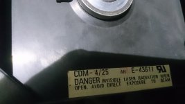
I decided to repair the drawer (was stuck and belt was almost gone), put a replacement belt and lubricated all gears with silicone lubricant, got it back working, then also did a good clean to the whole CDM mechanism, that's when I noticed that after all seems to be a CDM4??? Now this is weird. I once repaired a Philips CD150 which had a CDM4 laser fitted to a CDM2 mechanism and drive, as probably the laser had died. It had the update of components that's described in service manual but the label clearly stated CDM2. Also, the lens cover didn't have that horrible nut falling out. This one, on the other hand, has the oldest CDM2 servo board (the one with focus adjust), the laser really looks like CDM2 to me (but might be mistaken, as board does have some components soldered in afterwards), but the drive tray has label stating it's a CDM4??? Also the player supposedly is CDM2 originally, as can be found on net. May I assume this has been repaired with a new cdm4 drive which is a mix of cdm2 servo board and cdm2 or 4 laser? That doesn't make much sense, does it? Or did they simply put the sticker of new CDM4 laser on the drawer which is the same as original, from CDM2?

Now comes the most interesting part: after all this, I decided to further test it. Now it never failed again - read every CD I tried, even old blue CD-R with quite a few scratches and very badly scratched pressed CD. Great!! But why was it failing occasionally before?
Maybe some parts, like radial servo, needing to be used, to move, so to get "free" again after having sit non used for so long time? I did in fact noticed a slight "eek" when radial arm was moved.
Or can this be another case of "warm-up"? Maybe the infamous griplets which were the cause of failure reading discs in the cd150 I serviced? Yes, this also has them on mainboard. It's very similar to Philips CD-150, although with much nicer front panel and display and digital out.

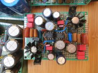
I'm going to put new electrolytics in main board and take the opportunity to resolder all the griplets. Hopefully no more random fails anymore ever then.

Now that it's ressurected, and another laser saved from erroneously being diagnosed as dead, I'm really motivated to do some simple and inexpensive mods (dedicated 5V for SA7220, cleaner supply for DAC, new opamp for output stage and audio grade caps in audio path) and then in the end sell it, as I already have a nice TDA1541 based player at home.

When all is done, I'll post more photos also of the rest of the player and final results. In the meantime, would be interesting to hear opinions about these random fails it had and which magically seem to have gone...

Also any additional suggestions of simple and inexpensive mods are welcome, thanks!

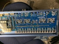
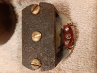
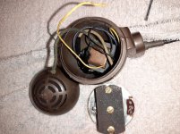
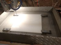
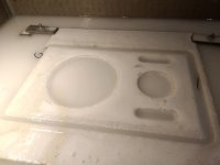
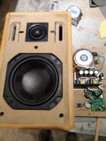
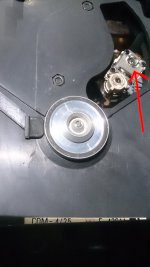
Attached photos show that plastic thing which had fallen off marked with red arrow and also sticker saying cdm4. Btw, the metal plate of the spindle motor where the CD sits on, has some kind of "residue" at its edges (is dark grey, almost black, easy to see in picture), is this "dirt" and should I scrap it off carefully or is this some kind of layer to better grip the CD which has deteriorated so I really shouldn't touch it at all??

Attachments

  • DSC_2287.jpg
    DSC_2287.jpg
    693.3 KB · Views: 385
  • DSC_2288.jpg
    DSC_2288.jpg
    565.9 KB · Views: 386
  • DSC_2286.JPG
    DSC_2286.JPG
    595.9 KB · Views: 380

Speaker outs connected together by mistake

I am selling a PA system - it did work fine - the chap coming to buy it wanted to try it out but got the speaker cables mixed up so ended up cabling the left speaker out directly to the right speaker out - plus cabling one speaker directly to the other. Obviously no sound but when called correctly still no sound.
Would connecting the two ‘outs’’ to each other kill the amp?

General question about speaker feet

With timber floors (or a wooden desk in the case of bookshelf speakers) what is the best "feet" to use. I have read quite conflicting recommendations in this regard (what? audiophiles not agreeing?).

On my Overnight Sensations I use those sticky felt discs that are deisgned to go on furniture to protect timber floors. This was what I had on hand and does a good job at protecting the speaker and the surface it is sitting on. I am about to build some floorstanders which will sit on my solid timber floor.

Is it a good or bad idea to decouple the speaker from a timber surface that it is sitting on from a sonic perspective? Other easy options I can think of would be a harder rubber pad which I imagine would have less damping effect on any resonance.

F4 Channel Problem - Running Cold

Hi All,

One channel of a F4 ran cold. Heat sink would not run hot like other channel. Originally thought problem was due to using a single turn pot for P2. Once replaced with multi-turn, channel ran fine. Then a few hours later noticed the stereo image was off again and the bad channel was running cooler than the functioning channel.

Not sure if it's a bad part or cold solder or other issue.
Here's some voltages of bad channel. Will get more.
Any recommendations where to look would help.


Supply voltage at board: +/-23v

P-Ch

G: -2.62V
D: -23V
S: -81mV

N-Ch

G: 2.96V
D: 23V
S: 81.0 to 81.4mV

D1: -2.7
D2: -2.7
D3: -22.8v
D4: -22.9v


TL431 (facing flat side, left to right)

Ref: -115.9mV
Anode: -2.62V
cathode: 2.9v

Thanks,

Vince
Projects by fanatics, for fanatics
Get answers and advice for everyone wanting to learn the art of audio.
Join the Community
507,833
Members
7,890,156
Messages

Filter

Forum Statistics

Threads
406,340
Messages
7,890,156
Members
507,833
Latest member
GaDysh