Recommendation for a decent DAC.

Can I get a decent DAC for around $200? Maybe a kit? I have a Mini-Muse DAC that I've been using for years now that I come to think about it. It's connected to my desktop computer and a vintage Kenwood amplifier it sounds great but I'm thinking I could do better seeing as DACs would have been improving over the years since I've had the MiniMuse. I don't have any SMD equipment so any kit would have to have the chips, etc, pre-soldered Any suggestions, ideas welcome.:tilt:

Speaker Positioning

Positioning speakers in a room is something we all do. How do we do it? What guides us? What works?

I mostly use my own version of Master Set. It works for any speaker in any room. Most guides and methods presuppose one has a perfectly symmetrical rectangular room. My room is quite irregular and thus I need the any speaker/any room way.

Learned a lot from the Dave Wilson 2016 video, especially regards the Zone of Neutrality.
See here: YouTube
You can also read this in any Wilson speaker manual.

I have posted what I do here: Master Set Revisited - 2019

Giving blood

It's been a quite while and I am considering doing it more often now that I'm a little older and wiser. So off to the local blood bank today to find a line-up. Yes, a line up. So much so, that I was not going to be able to donate for about an hour and a half. Not kidding. Didn't have time but as I drove off I got a right wonderful feeling knowing that so many cared.

As they say "Blood, it's in you to give."

BTW, this was the permanent location not just a mobile unit. The lady suggested I make an appointment. I smiled. Lotsa good folks out there.

Velodyne CHT-12 QR Service manual needed

Hi to all members. I am looking for Velodyne CHT-12QR Sub Service Manual. As commonly known around, class D amp is the most sensitive part and mine burnt out yesterday. Unfortunately, local distributor informed me that it is not available for purchasing, only repair by them. As you can imagine, repair price would be more than purchasing of a new and modern piece. So, I am looking for service manual in order to replace damaged amp by another class D amp (from Ebay). Power supply is working perfectly. I managed to decrypt some of pins and cables (power, signal) but not the auto-start feature. There is always power available. Looking around net, I found out that DEQ-12r and maybe SPL-1000 are quite the same. Also I saw some internal photos of CT-120 that looks same to mine. So I would appreciate if someone can post or send me a service manual of above ones.
Thanks in advance for your kind attention and help.
Regards from Greece,
John

voice coil inductance

Hi!

I have found a pair of burnt-out vintage Celestion HF1300 tweeters, and I would like to endeavor into the task of re-winding the voice coils to get them working again. The VC "body" seems quite robust, so I have some hope to succeed. However, the copper is so damaged that I have a hard time figuring out the number of turns, or even if it is a single layer or double layer coil, etc.

One hint is the specs, I think I know that this tweeter has a specified coil inductance of 0.2mH, nominal impedance 16 ohms, dc resistance 13 ohms. If I use a coil inductance calculator, and just guess a wire diameter of 0.1mm, coil diameter of 25mm, a double layer of about 4.5 mm length, and a wire length of 6 meters I get 13 ohms and around 208uH in air.

Is this approach reasonable?

I know that an air coil will NOT have the same inductance as when the magnet iron is present, but as the speaker magnet system is not a closed magnetic circuit (only half-way) the magnet might not add too much anyway?

I think I understand that it is not the inductance itself which is the primary goal, but it is rather the motor properties which is important.
But if the resistance and inductance are in the right ballpark for the selected coil geometry, will not the motor be just about right too in the given magnet system?

Comments and suggestions are very welcome.

And YES, I have scouted eBay. Parts for 16 ohms HF1300 seems unusual and are not very likely to be found.

BN

aiuto con il tda7293

good morning everyone how are you?
I take advantage of your patience and courtesy again:
the point is that i have a problem with the ic tda7293.
i tried to build an amplifier several times but it never works.
I am using some pcb boards already made, and with different configurations, but it never works for me.
I read on the web
and also on the forum, that this i.c. has mute and stand by controls that should be excluded to make it work, I tried to follow the instructions, but it doesn't work anyway. can you help me understand why it doesn't work?
on the same pcb I mounted some tda7296 and they work perfectly, but the tda7293 no.
thanks for your attention.

Beefing up the TV audio

I'm not sure if this is where this would go, so please re direct me if so.
So I know this is not the norm but I decided to have a little project with my son, so we added two small satellite speakers in series with the TV's internal speakers. The TV has 6ohm speakers and the satellite speakers are 4ohm. I did it in series so it wouldn't be too much load on the baby chip amplifier on the TV. The problem I'm having is that the satellite speakers are louder than the TV speakers. I was thinking of adding an inline pot of some sort to the satellite speakers. While rummaging around I found some 6ohm 5w pots from some old CV tower speaker crossovers I had laying around. Could I use those to do so? It's a pretty low watt system obviously so I don't see the TV being too much for them. I know this isn't really all that interesting, but like I said. It's just a project with the kiddo.

SB Acoustics Audience Line

Noticed Madisound is now selling SB Audience line. Looking at the Nero 18” and 21”, they seem among the highest efficiency drivers around and in typical SB fashion the price is right. Anyone have any experience at all with these. After doing Troels “The Loudspeaker” and building a SET amp I have the high efficiency bug though not a fan of horns or single driver systems.

Can’t find much on the lineup besides AX test on the budget compression driver. I’m thinking of a 3 way targeting as close to 100dB as I can get and hoped I’m not the first to use these drivers! Guess I could start with building HT surrounds 2-way as a test...

TJ Full Music 300B mesh plate and Elekit TU-8600R

Hi DIYAUDIO forum members!

I have a question about the Full Music 300B mesh plate and especially if that tube is a good match with my Elekit TU-8600RV.

I understand that it has something to do with the measurements of the 8600 but I am far from even a little knowledgable in these matters so I was hoping to find an answer on the forum.

Does anyone have any experience with these tubes or other mesh plate tubes on an Elekit 8600? Would love to hear from you!

REW measured impedance too low

Hello!:wave:

I've been using REW to measure the impedance of my home made speaker drivers. The impedance curve I get has the correct shape (the Fs is correct), but the problem is that the impedance itself is unrealistically low for an Re=5.4ohm driver, as can be seen in the picture attached.

I have calibrated the measurement setup the way that it is instructed in the REW impedance measurement manual. I have also measured the Rleads by making a measurement without any load. Is there anyone who would have encountered this problem before?

I'm using PreSonus AudioBox USB 96 sound card and it's own ASIO driver, and I have checked many times that there should be no errors in the connections. I was already able to find the Vas with the Fs of these results, but I want to find the optimal enclosure volume for my drivers, and to do that, I need the Q parameters. If I have understood it correctly, the maximum value of impedance is necessary to be known when calculating Q parameters.

Attachments

  • problem.PNG
    problem.PNG
    131.8 KB · Views: 228

audison vr 203 problem.

hi guys, i have a problem with a broken audison vr 203.
I have replaced both pnp of the channels because the short, original mounts 2n6491 I have put some bd744c.
green led on the amplifier works, but as soon as I press the stereo / mono selector, or the sensitivity selector, a bump and amp in protection, on all op ne5532 I have positive and negative voltage 14v. rail 27v dual.

Design process for getting correct DC heater target voltage (newby)

heater11.jpg

Newby question, this is my first use of a DC filament supply...

Using old fashioned trial and error...

I'm making a DC heater for a single preamp tube (one 6SN7) tube which draws 600 ma of filament current.

After rectification and filtering my supply is now delivering 7.34 volts with no load, the transformer is 6V and capable of 6A, bridge diodes, only a single 10000 uf capacitor as a filter, no RC filter. At my mains voltage the transformer outputs 6.54 volts AC.

(very similar to the schematic shown which came from valvewizard)

What is my (trial and error) design process here?

  1. Should I get the no load voltage dropped to 6.3 maybe by adding a series diode or two before I use this supply? Then just plug in the tube and go, Knowing there will be a slight voltage drop across the tube.
  2. Or should I first load my supply to 600 ma on the bench by selecting the proper resistor, then adjust things so the loaded supply is delivering 6.3 V? Knowing that the unloaded voltage will be slightly higher.

Basically which comes first the chicken or the egg?

Also in experimenting I've been careful to use a Variac and meter and test with a mains voltage that is true to what I actually have in my home. My mains are very stable here rarely going lower than 122 V or higher than 123 V.

I dont want to run the tube too hot or too cool, just right, maybe 5% tolerance.

Audio Labs DQ40TZF-02 Drivers Seem Uninspiring

Hello,
Few weeks ago the Audio Lab DQ40TZF-02 drivers i ordered arrived, but have been nuts too to try them. So finally yesterday I had couple of hours spares and made a pair modest 18mm ply 260x150mm baffle boards for them. Now i realize the baffle boards are small but i must admit that i am really disappointed with the sound from them, also they seem to required quite a lot of power to get even modest volume from them compared to a pair of old BR 5" missions.

Single piano notes maybe not too bad, but speech and multiple instrument is just a jumble.

So I am wondering are these drivers truly that bad and not worth building proper cabinet for, or is this test simply invalid considering the modest size of the baffle boards?
Many thanks IMK

Parasound HCA-1000A Fault Indicator Red Light

I have an older Parasound HCA-1000A power amp that has developed an issue where it's red LED "Standby" light is on all the time now but I'm still getting sound. The amp was modified years ago but never exhibited this issue until recently. Typically, when working correctly, when powered up the amp displays the red standby for a few moments while the relays are working and then you can hear a click and the red light goes out and the green LED "Normal" indicator comes on. Here's the weird thing. I noticed that when I disconnect my interconnect from the amp to my preamp the amp does not display the red LED standby light, it actually goes green and I hear the relay click. So, when the amp and preamp are connected with an interconnect I get the red LED Standby light (though I still get sound). It doesn't matter if preamp itself is on or off by the way, it exhibits the issue. I did try another interconnect just in case by the way, made no difference.

Here's a snippet from the Parasound owner's manual:
-------
The Standby LED will also light whenever there is a short circuit or other fault that triggers the protection circuitry. This may indicate that excess DC is present at the amplifier's input, a speaker impedance overload, a short circuited speaker line, or possible internal fault. If this LED remains lit, remove power to the amplifier and check all connections. During this time, the protection circuits should automatically reset.
-------

Once again, never had this issue with this amp over the years until recently, suddenly out of the blue. Seems to be related to the RCA inputs and my preamp's output. Since nothing has really changed in my setup is it possible that perhaps it's a relay or maybe even a cap associated with/near a relay is out of spec and and throwing the red LED? Odd thing is I still get sound, the amp's output is not muted in protection mode. I do not get a huge thump when I turn this amp on by the way. Any help would be appreciated, thanks!

Very shallow center channel

Hi

I'm moving to a much smaller place and my old center channel simply does not fit in with my plans for the new place what so ever.

I would really like a very thin/shallow of 76MM(3") at most. I've found a few center channels that are that thin, but they all suffer from one or more issues.
Ugly, expensive or just not available here in Denmark.

I'm currently looking making a center speaker in the style of the Beosound Stage soundbar using 2 Peerless HDS(Or SLS) 134 (5.25") units. Since they are not vented to the back of the magnet system and shallow enough for the case. Maybe also play around with some passive radiators

If you know of a similar project or some drivers that would fit such a thin case. Please let med know, any help would be greatly appreciated. I've looked at an insane amount of speaker units and the Peerless units seems to be the only ones suited for this project

Hypex NCxxxMP H Box connectors

Hey all,


I am in the works to start building Hypex NCxxxMP based amps in the US (just got my OEM account approved and have a mock-up for my case being worked on from Protocase). I am making a list of all the parts I need, but the only two things I am having trouble acquiring are the female connectors for the J4 and J6 H Box connectors.


I have the exact male connector parts from the Hypex datasheet, but all I can find are ribbon cable female connectors. Since I am doing XLR only builds, I need connectors that can have my own wiring connected, just like the Ghent Audio cable harnesses.


Does anyone have an exact match part for female connectors that work with the J4 and J6 H Box connectors that allow for individual wiring with crimp style connectors, much like the power and audio out connectors on the board?


Thanks!

FS: LS3/5a - Harbeth clone project

As I have way too many speakers - they are going for sale: 400,- Euro incl. shipping in Europe - Mini Monitors as described in this link: https://www.diyaudio.com/forums/mul...tion-designing-crossovers-measurement-70.html

Attachments

  • IMG_1007.jpg
    IMG_1007.jpg
    989.2 KB · Views: 710
  • IMG_1011.jpg
    IMG_1011.jpg
    718.1 KB · Views: 678
  • IMG_1008.jpg
    IMG_1008.jpg
    979.8 KB · Views: 663
  • IMG_0999.jpg
    IMG_0999.jpg
    1 MB · Views: 663
  • IMG_0981.jpg
    IMG_0981.jpg
    1,011 KB · Views: 704

Greetings from Finland!

Hello!

I'm quite new here so I wanted to introduce myself here. I'm 24 years old guy from Finland, currently working on a building acoustics / HVAC company. I'm almost a M.Sc. in acoustics and audio technology which gives me a lot of understanding about some theorethical aspects of audio things. However, I see that real practical experience often gives much more overral umderstanding on what actually works, and in that sense, I'm still a beginner.

I'm interested in many kind of diy-projects, mainly related to audio devices. I still don't have very good woodworking places or tools, so I especially enjoy all creative, relatively low budget diy projects, where I don't need any expensive tools, but where I can really make use of my small dremel 🙂.

I've already made couple of threads (one related to my current DIY driver + aperiodic box project) and I'm positively surprised about the friendly and helpful atmosphere.

Edit. Also, I forgot to mention that I enjoy making music! I don't want to push too much and bother others too much with marketing it, but if you're interested, just search my name on Youtube or something. I mainly make electronic music.

How would you judge this room measurement?

Hello guys, as per title how would you judge the measurement of my listening room from the sweet spot?

I attached the 2 channels (L/R) REW files. There is an emphasis between 100 and 200hz but i think it can be speakers design...i still don't think it's a big issue.

I don't know about decay and sub integration (crossed over at 75hz) as I'm not yet expert with reading these values in REW...

The room has a lot of Bass Traps but i could not do much because of the shape (it's an attic).

What is your opinion?

Thanks


LR - REW.zip - Google Drive

40watt push pull class A amp suggestions

I am thinking of building an amp for driving the electrostatic panels of my ML Aeon hybrids.


They aren't an easy load, with the impedance dropping to below 1.32r at 20khz, but the crossover is at 450Hz so the opt does not need to be anything special.


I'm not experienced with tube amps, so don't know whether I want an opt with UL taps, what HT I should use, and whether to stick to a pair of EL34s, of use something like KT88, or KT120s.


Please point me to a suitable schematic


A pair of these mains transformers seems suitable. Power Transformer Guitar Amp Valve Tube 6L6 DIY Supply Push Pull FIRM Components | eBay


and have a 40vAC winding for biasing.


For opt Hammond 1650HA 6.6k 200ma

Help for repair Harman Kardon power amplifier HK770

Hello,

I have an Harman Kardon power amplifier HK 770 but he have little problem.
This HK770 is buying by my father around 80's but around 97's have problem with it. The power don"t work correctly and out voltage at right chanel and burn the speaker . . . .
I take this for try to repair.

I have one diode burned and cut in two parts. Is the diode D420 (Ref HK : 5632-ERB12-02) Diode, ERB12-02.
When i look on internet is look like Silicon Rectifier Diode from Fuji Electric.
But actually this diode is discontinued.

HK Service manual on my dropbox : [wiki=https://www.dropbox.com/s/52j8lodmxysk9mu/hk-770_SM.pdf?dl=0]%[/wiki]
Datasheet find about the ERB12-02 : [wiki=https://www.dropbox.com/s/6oe1lt8ioyxanqk/erb1202.pdf?dl=0]%[/wiki]

Can you help me for find an equivalent for replace this parts !?
(I don't know what information is important on the datasheet for find replacement parts. Have many type of diode on the market : Diode Zener, TVS, Rectifier, Schottky etc.. and have only HK ref : ERB12-02).
I put picture of the diode on my dropbox :
Pic 1 : [wiki=https://www.dropbox.com/s/vygv24ue32bpgig/Diode_1.jpg?dl=0]%[/wiki]
Pic 2 : [wiki=https://www.dropbox.com/s/5fpj3424l1j5sj9/Diode_2.jpg?dl=0]%[/wiki]

Thanks for the help

Best regards

FS CGOLDENWALL JST Pulse Battery Spot Welder

Hello,

For sale a battery spot welder good for 0.03mm to 0.15mm nickel strip welding.
It has very light use with less than 500 welds.

I bougth it from here: CGOLDENWALL JST Pulse Battery Spot Welder Small Hand-held Soldering Welding Machine Micro-Computer 18650 Battery Charger Power Bank 0.03-0.15mm (220V): Amazon.co.uk: DIY & Tools

Sold

Attachments

  • image1.jpeg
    image1.jpeg
    80.7 KB · Views: 168
  • image2.jpeg
    image2.jpeg
    89.1 KB · Views: 171
  • image3.jpeg
    image3.jpeg
    78.9 KB · Views: 159
  • image4.jpeg
    image4.jpeg
    107.7 KB · Views: 167
  • image0.jpeg
    image0.jpeg
    122.6 KB · Views: 165

Advice needed on Ruark Crusader 2 Speakers

Good day all.

I have a set of Ruark Crusader 2s, and the mid-range on the one speaker is giving distortion. It does not sound like mechanical distortion, so I believe it could either be a dry soldering joint, or bad capacitor in the cross-over.

I have attempted to open the speaker up by removing the driver(s), so I can get to the crossover, but are unable to get the drivers off, even after removing the driver screws. Are these drivers also glued onto the box by any means?

Any advice welcome.

Cyrus Preamp aCA 7.5 repair or scrap advice

I would really like to restore the output to my preamp but am fully aware from reading some of the Cyrus related threads here that this is unlikely to be a DIY success. Not least because there are no circuit diagrams available even for experienced audio electronics engineers to access.

So my key question is whether there might be a straightforward diy check that could result in a safe diy repair?

The issue with my unit is that it powers up fine and does not go into error mode ie orange power light or shut down. The unit has never blown a fuse and I can't think of any time it has been subject to a mains surge.

The headphone part works without issue, full volume control and sounds really good. There is though no output from the pre-out into my Smartpower amp. I have tried both pre-out 1 and pre-out 2. Input is fine across CD, Aux etc and all provide undistorted sound to the headphone ouput.

I opened the unit and found that the two large blue 4700 uf 40v caps (c319 and c317) were showing 3500 uf so replaced. Also noticed that one of the 100 uf 50v caps was bulging so replaced both with Nichicon Muse equivalent. This is as shown on the attached pics.

I have closely inspected the traces under the board using a magnifier and can see nothing that looks broken.

Those who are familiar with Cyrus will know that this is not a supported unit and even when it was there was a whopping £300 plus postage charge which is far more than it is worth.

I am really reluctant to bin this but before reaching that conclusion thought I should run this past the highly knowledgeable members on this forum. If you are able to help that would be welcomed and might result in one less bit of landfill.

Initial internal photos attached for reference.

Attachments

  • Cyrus aca 7.5 (1).JPG
    Cyrus aca 7.5 (1).JPG
    87.1 KB · Views: 354
  • Cyrus aca 7.5 (2).jpg
    Cyrus aca 7.5 (2).jpg
    165.8 KB · Views: 310
  • Cyrus aca 7.5 (3).JPG
    Cyrus aca 7.5 (3).JPG
    113.1 KB · Views: 461
  • Cyrus aca 7.5 (4).JPG
    Cyrus aca 7.5 (4).JPG
    98.1 KB · Views: 571

Linn Kairn Repair

I just bought a Linn Karik and a Linn Kairn for spares or repair. Both were dead or showed very little life, I paid £120 for the two with remotes.

The Karik was completely dead and showed no life, it had a silver slimline Brilliant supply in it that a HiFi shop had tried to fix but failed. Using a MM there seems to be nothing out of that Brilliant.

The Kairn would only show the green LED, dimly. It also has the silver slimline Brilliant in it and that showed life on the MM.

I swapped the Brilliant from the Kairn into the Karik and the Karik now works fine 🙂

The "repair" on the other Brilliant is Sub Optimal as in there are at least two capacitors that were loose and on one of the large capacitors the solder pad has come away from the underside of the board. Am I right in thinking that the only connection to those capacitors is on the upper non pad side? If so I will attempt a repair of the pad.

However that still leaves me with the Kairn. This does not seem to be a PSU issue as the PSU originally in it is working fine in the Karik.
(Unless the Karik does not use all the Rails from the Brilliant?)

I have had a quick look at the main board for obvious Caps damage and the like and I cannot see anything. Any advice on what usually goes wrong on these?

However, when I took off the front I could see that the battery is corroded but I cannot see much damage from corrosion on the PCB and have tested out the lines I can see with potential damage and they seem OK. One SM Capacitor is hard to read but that could be because it is in circuit(?)

Any ideas on what to look for?

The white is the damaged tracks but they are showing continuity. Purple is the capacitor I cannot reliably/at all read. I have removed the battery in this pic.
49061355033_e6a08bd14e_c.jpg


Corrosion/Leaking Battery
49056672007_172d98b8a3_c.jpg


49056455661_09db0ea6b6_c.jpg

Pin to pin jumper for tube tester - Sencore Mighty Mite

I only own only four items using tubes so no frequent need of a tube tester.

Yesterday, I spotted a local ad for a Sencore TC-114 "Mighty Mite" for $50 snd picked it up. No tube chart included but I downloaded a copy.

One tube that I would have occasion to test are 6AU7's and the chart explains that....

...."for (their) tube tester models without a socket #13 a 6EU7 tube inserts into socket #3 with a jumper wire between pin 5 & pin 1".

This TC-114 is a model without a socket #13. Would the accepted method mearly be to wrap a thin, non-insulated wire around those tube pins prior to insertion or something more elaborate?

Castle Trent 2 Tweeter

I was dismayed to discover one of the tweeters silent on these speakers i have loved for 20 years!
Checked output at the crossover ok, found the tweeter to read about 1K, so unfortunately not broken at the leadouts where a repair can be done. The other reads about 8R. I play loud, but not to have overloaded, but maybe so? I can see the ferrofluid still looking wet in the gap.
Has anyone been through this and where to get a pair of tweets to suit, any ideas most welcome!

Subwoofer Not Working

I have an old ACI Titan II sub that was making a very loud buzzing sound. Woke me up in the middle of the night. I put my hand on the speaker and it was loose. Not the screws that hold the casing but the cone with the rubber surround became detached from the casing? I turned over the sub and using some black silicone adhesive I re adhered the speaker to the casing. It moves well when pushing it in with my fingers. I also read the coil with an ohmmeter and it read 4.7 ohms. I'm assuming it's good?
I decided to pull out the amp and have a look at it. The amp has a big toroidal transformer and two Nichicon LQ (M) 6300uF 63 wv caps that both were a little bulged at the top. One a little more than the other. I decided to replace them with two Nichicon LS (M) 6300uF 63 v (not wv).

Getting the old caps out (snap-in and solder) was a little difficult but it seems I was able to do it without destroying the circuit traces as I have done in the past with other pieces of equipment. Put the new one's in and all I get is the unit powers on but the woofer does not respond to any signal.

Any ideas what is wrong? Could I have damaged something while replacing the caps or was something else damaged when the woofer became detached and was making that loud buzz for I don't know how long until it woke me up?

I'd appreciate any help. I'd hate to have to get rid of it when it may be just a simple fix.

Thanks, Nick

Help to understand and build regulated power supply

ive got some toroidal 24v 200va dual windings

ive got 20 of them could not throw them away..
i have some elektronic knowledge.
i want to build power suply for an amplifier.


ive been looking at

13.8V 20A linear power supply


i like the design but i vant higher voltage. up to 40v

can someone help me with this?


and can i put transformers in parallel and series for higher voltage and va?


Cheap speakers with big sound

I used 3 way speakers Jensen with 12" bass. I changed it to 12" full range Electrovoice /92 dB, 30-13000 Hz/. I disconnected middle. Sound is cool, better some expensive speakers. Its very easy to build. I use with my DIY SE 2A3 RCA and Im very happy! /40 $ for towers and 200 $ for 2 El.-Voice/.

Attachments

  • IMG_4447[1].JPG
    IMG_4447[1].JPG
    396.8 KB · Views: 280
  • IMG_4305.jpg
    IMG_4305.jpg
    551.7 KB · Views: 272

  • Locked
Real RIAA preamps versus real loads

I found it really unfair that a very interesting thread on BJT and FET preamps was closed because the original creator personally thought it was taking a direction he didn't like or was interested in. The thread was this:

https://www.diyaudio.com/forums/analogue-source/357649-fet-vs-bjt-input-phono-preamp-new-post.html

I didn't think the original thread creator could ask moderators to close a thread because of an opinion. If that is the case, then it is wrong, it should be changed.

A thread does not belong to anyone, and if things started to go the direction they went, incorporating in that case a very important element to the equation, which was cartridge load, it was because the whole system of a RIAA preamp, could only be considered complete when the cartridge is included.

In that case because of what the simulations, LTSpice or any other, that I think were brought in to the action. Other participants, like Marcel vdG and Hans Polak, added their own information, and warnings, about cart and preamp interface. Hans did start showing some LTSpic sims.

I disagree completely that the suggested thread was the one to discuss the interface beween a cart and a RIAA preamp

https://www.diyaudio.com/forums/analogue-source/303389-mechanical-resonance-mms.html

The OTs claim arguing why the thread should be closed is completely wrong and does not sustain itself. His arguments are not valid and do not apply to the rules of this forum.

What should have happened is a warning to his behavior, instead of closing the thread.

Choosing tubes for VTA ST-120 (Bob Latino)

This may be out of place here. If so, I apologize.
I've only owned one tube amp and quite new to this.

Basically the question is should I spend more money on output tubes or would I benefit by getting a more powerful rectifier - if I am phrasing that correctly?

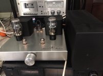
I've had my ST120 for a couple years and wildly pleased with it.
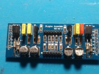
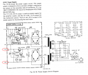
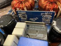
The other day I had a 6550WE red plate. After a bit of reading it appears I need to replace the 10ohm 2w resistor and I intend to replace the one bad tube with four new ones because, WHY NOT?

I have never "tube rolled" so I am going to lean on the greater knowledge of this group.

I imagine speakers and music should be considered when "rolling tubes"? It's all a sonic relationship.
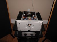
My system
Preamp: NAD C658 running Dirac Live
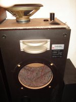
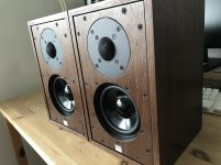
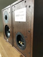
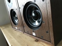
Speakers: Goldenear Triton Five
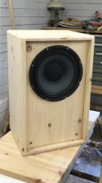
Subs: 12" sealed cabinets x2 powered by a Peavey CS800x (temporary power)
Music: Mostly Tidal via Roon though have Pioneer Elite PD-65 cd player and an AT LP120 turntable.
Artists: Tord Gustavsen Trio, Pink Floyd, Taylor Swift, Nora Jones, Lyle Lovett, Aurora, Beck - if it has imaging for days and sonically interesting, I'll listen to it.
What are my goals: IMAGING & TONAL BALANCE.

I've spent years and years trying to setup a system that is balanced and the speakers disappear in the room. I finally have it; Tord Gustavsen Trio are 10' through the wall, Yello's Planet Da Da (flamboyant mix) has sound seemingly coming from behind me, and that low bass in Boz Skaggs "Thanks to you" rumbles my underside.

As of now the ST120 is delivering very little bass due to the 70hz crossover I set by Dirac to integrate my subs. I have, at times, disabled the subs and driven the Tritons full range but only for a few minutes at a time. The bass output is impressive, the speakers and amp, but I have not done so at length.

In the future, however, with "Dirac Live with Bass Control" I'll have the option of delivering full range to the Triton Five's and Dirac will integrate the subs seamlessly. So, in the future the ST120 will be delivering full range output.

I could swing a set of GL KT88's, or a set of 6550WE's and a GZ33 without much concern but, I'm not sure what the benefits of either decision would be? I'm not even sure how a rectifier can affect the sound - from what I gather it has to do with headroom.

I plan on ordering parts on Tuesday, hopefully I will have some help from you folks by then.
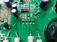
Anyone fixed a Bose Wave Radio with no sound?

Hi Everyone,
My old Bose Wave Radio, Model AWR1- 1W, recently stopped working.
At first it wouldn't power up at all. I got hold of the service manual and guessed, correctly, that a likely cause was the R6 resistor. I replaced it and that fixed the power up issue but it remains with no sound. All the displays are OK - stations, volume, clock etc. just no sound.
If you know how to fix or troubleshoot this problem I would appreciate hearing from you.
I've just joined diyaudio on a friend's suggestion. Also checked previous posts and haven't found any relevant info.

thank you.

Aleph 5 Clone

Hello all,

Built this amp years ago and sadly need to let it go to next owner. The chassis is a monster DIY effort from a fellow DIY'er here on this site. The chassis is a very nice crafted Aleph X design with monster heat sinks

The amp is a Aleph 5 from Brian at Chipamp.com. The PS tranny is a quality Piltron, and has four 56kuf caps.

The unit get nice and toasty and runs full out bias with the set resistor (R19) pulled. The power supply has 140F switches on the sinks. Currently have only Balanced inputs, but SE RCAs are back there - more pics forth coming...

I do not want to ship as I have NOT been having good luck with shipping lately (send and receiving)

Also have a circular Aleph X Meter (cheapie from ebay) that needs the center holes reamed to be inserted.

So local pickup - West sub of Chicago... $650

Attachments

  • Alephinside.jpg
    Alephinside.jpg
    124.1 KB · Views: 907
  • Alephfront.jpg
    Alephfront.jpg
    102.3 KB · Views: 875
  • Like
Reactions: RXV

Need help with DLM4500

I know that there are a few threads on this DLM4500. But I am stuck on this amplifier and I need help. All I need is the small daughter card on the DLM 4500. The version I have will not fit a lm319 and tl072. Can anybody help me on where to find just the daughter card or help me with the PDFs so I can make my own daughter card that fits an LM319 and TL 072. I'm working on a very sentimental amplifier and I really don't want to shelf it. I have called dozens of places to see if they had a DLM 4500 and they are not very helpful. It seems like we are community sometimes but other times nobody wants to help in up-and-comer. I'm just learning and basically self-taught but I love working on amplifiers and I love the whole car audio community. Thanks, Amp Gutz

Attachments

  • IMG_20201008_184758611.jpg
    IMG_20201008_184758611.jpg
    827.6 KB · Views: 128
  • IMG_20201007_171948416.jpg
    IMG_20201007_171948416.jpg
    845 KB · Views: 98

GROUNDED GRID

I am using a phono amp with a grounded grid first stage. It has a bad habit of picking noise up from other things plugged into the same circuit. It seems to usually be from any switching power supply on the same power supply. The same phono amp will make no noise in a different system. My questions:

1. Where is the noise getting into the amp
2. What can I do to fix it?

I have used powerline cleaners with no reults.

Attachments

Hammond 156C as plate choke

I've used 2 of these in series in humbucker arrangement for DHTs like 26 and 01A. I no longer use these tubes, more like medium size drivers with 16mA current.

Spec is 8mA, 150H, 3700R.

So before I build up something with two of these in parallel, how is it likely they'll function? I should get 16mA, 1850R, 75H. But what of the doubled capacitance? I don't have measuring equipment to check the frequency response, so can somebody hazard a guess at the results - maybe a loss of treble?

Can anyone identify this IC

Ok... I'm doing some repairs and I'm having trouble finding a data sheet for this IC and thought maybe someone here might have seen this before. It appears to be distributing a clock signal of ~11.2896MHz to four AK4524 Audio codecs... Here's a pic.

attachment.php


The markings as far as I can tell are as follows:

MK70-1
231120A
0240CA


If I have the orientation correct then the output on pin 6 is going through the 33ohm resistor and then to the four AK4524 codecs...

I've tried Google and distributor/manufacturer websites, but came up empty. Does anyone have any idea what this is and what the pin out is?

Attachments

  • IMGA0420.jpg
    IMGA0420.jpg
    36.9 KB · Views: 301

Nakamichi 700 II PCB Power Supply problem.

Hi to everyone...

A few days ago I took on the task of rescue my old Nakamichi 700 II (1973-79) and the first thing I come across is a lack of 12 Volt output from the power supply PCB, the voltage It is not stable and varies randomly to such a degree that in the multiple measurements I made I registered 0. 4.5, 9.7,12.5, 13.2 and even 14.6 Vol. All of the above once you have tested the output of the corresponding winding in the transformer and checking that it is correct . In fact, the outputs that feed the vumeter bulbs are correct and they turn on when current is applied to the equipment.
I am not a scholar on the subject, I checked the 8 main components of the 12vol stage, the rectifier package, the two transistors, the capacitors and the two resistors but still I cannot find the origin of the problem perhaps due to my inexperience in the subject of checks on components.
I am very grateful for the help of a good Samaritan who enlightened me about it and guided me to the right path to solve this little problem.

Please see attached images and sorry to google for the bad translation

Attachments

  • Nakamichi 700 II.jpg
    Nakamichi 700 II.jpg
    809.3 KB · Views: 200
  • PCB Power Supply Nakamichi 700 II.png
    PCB Power Supply Nakamichi 700 II.png
    621.1 KB · Views: 166
  • Power Supply Nakamichi 700 II.png
    Power Supply Nakamichi 700 II.png
    558.9 KB · Views: 192

Hifonics BRX2016.1D

This amp uses IRFP064N with 47 ohm gate resistors .

Does anyone know the value of the pull down resistors ?

Attachments

  • 65CF665B-8A9E-4E1E-9DBB-32BE3DB893D2.jpg
    65CF665B-8A9E-4E1E-9DBB-32BE3DB893D2.jpg
    1 MB · Views: 120
  • 2724CAFE-DB44-4CF8-A38E-B3D3A2D88B37.jpg
    2724CAFE-DB44-4CF8-A38E-B3D3A2D88B37.jpg
    1 MB · Views: 102
  • DF147D4A-D331-4978-80F6-ED3F7AEC5D5B.jpg
    DF147D4A-D331-4978-80F6-ED3F7AEC5D5B.jpg
    1,014.7 KB · Views: 110
  • 6B5A90E3-397C-4406-B9CC-D79C4DEBEDD8.jpg
    6B5A90E3-397C-4406-B9CC-D79C4DEBEDD8.jpg
    957.7 KB · Views: 101
  • 120D17EB-0C34-414E-A5AF-352417BED206.jpg
    120D17EB-0C34-414E-A5AF-352417BED206.jpg
    983.8 KB · Views: 121

Who sent me this FM transmitter?

Some weeks ago, I received this miniature FM transmitter:

attachment.php


I didn't order it, and I didn't discuss the subject with other members.

A number of members have my private address, but nobody sent me an explanation.
I sometimes order goods from Banggood, but I didn't order anything for quite a time, and I never ordered this.

I do not know what I am supposed to do with this module. Test it? What parameters?

Attachments

  • FMTx.png
    FMTx.png
    316.3 KB · Views: 356

AP 2722 Questions

Hi,

Would someone be kind enough to let me know if they have experience with the model described below, and where it sits within the 2700 line up? The 2700-series has a myriad of options and I'm no expert on identifying a desirable model from one that is less so.

I have tried the 2722 with its oscillator routed to a UPV. True enough, the AP oscillator has around 2dB lower THD+N @ 1KHz than the UPV-B1 oscillator (usually gives -113dB THD+N, whereas AP nudges -115dB @ 2V RMS). I guess I'd need an AP555 to work out whether the analyser section of the 2722 or UPV is better.

I have seen people claim to have calibrated their 2722s themselves... Is this possible if you have another analyser (namely a UPV-B1-B3)?

Out of interest, what would be a ballpark price to ask for this analyser? I see them for stupid money on Ebay, but am fully aware that this is a false reality and real world prices are lower. If calibration is around £1,500-2000, is it worth doing it in order to sell it?

Thank you in advance!

This is taken from running the self-test routine:

Year of manufacture 2001
Model number: 2722-96K

IMD Option CHECKS
11/12/19 16:16:54 **********************************************
11/12/19 16:16:54
11/12/19 16:16:54 IMD option is not present in this instrument. Checks aborted.
11/12/19 16:16:54
11/12/19 16:16:54 **********************************************
11/12/19 16:16:54 BUR Option CHECKS
11/12/19 16:16:54 **********************************************
11/12/19 16:16:54
11/12/19 16:17:00 BUR option is not present in this instrument. Checks aborted.
11/12/19 16:17:00
11/12/19 16:17:00 **********************************************
11/12/19 16:17:00 WFA Option CHECKS
11/12/19 16:17:00 **********************************************
11/12/19 16:17:00
11/12/19 16:17:00 WFA option is not present in this instrument. Checks aborted.
11/12/19 16:17:00
11/12/19 16:17:00 **********************************************
11/12/19 16:17:00 AES17 Lowpass Filter Option CHECKS
11/12/19 16:17:00 **********************************************
11/12/19 16:17:00
11/12/19 16:17:00 AES17 Filter option is not present in this instrument. Checks aborted.

Technics SB-1950 interior filler unknown

A few years ago I repaired (changed the foam wings) some Technics SB-1950 cabinets.
I had never seen anything like it.... 😱
Can someone explain what is the theory behind the use of this terry cloth stapled inside?
The cloth divides the inner compartment in two, so the tuning tube is tuned for the upper or lower volume ?
Or for the total volume, because it is the same as putting a sock inside the duct, the air will pass anyway?
Opinions ? 🙂

Attachments

  • Reparación speakers Technics SB-1950 015.JPG
    Reparación speakers Technics SB-1950 015.JPG
    666 KB · Views: 291
  • Reparación speakers Technics SB-1950 002.JPG
    Reparación speakers Technics SB-1950 002.JPG
    613.2 KB · Views: 324
  • reparacion bafle technics sb1050 049.JPG
    reparacion bafle technics sb1050 049.JPG
    386.2 KB · Views: 233

Need some guidance for Solid state relay.

i have made a magnetizer for charging loudspeaker ferrites. It is working well at 1500vdc. Currently I am using a mechanical switch to discharge capacitors into the coil for magnetization.

Now i want to implement SSR relays or thyristors but i don't understand its work and if I want to buy ready made ones then there is nothing available above 1200vdc. Also the guy who sells it says it cannot be used in series.

Any guidance can be very helpful. sorry for my English.

cdp-x33es right channel distorted

Hi there,

I bought a defective sony cdp-x33es, the problem with the player is that the right channel is distorted.
After changing all the red Duorex II caps (which were almost all leaking) for Nichicon Finegold caps the problem is still the same, but if i let the player play for 3 minutes the right channel is suddenly good again...

Any idea what else could cause this problem?

thx!

Rubbereend

In search of the perfect baffle

I was always impressed with the sound and looks of speakers from the 70s.

They were effective, simple, easy on the eye and had a logical driver placement for 3 way systems with larger bass drivers than what we typically see today. Speakers of this era also had a lot more enjoyable "body" most likely due to the larger bass drivers and wider baffles, compared to today's narrow floor standing towers which I never liked. Which is one of many reasons I'm into DIY, I want to create similar sounding speakers but with more up to date technology and driver quality.

My first pair of speakers as kid was an inherited SEAS/Dynaco A25 DIY kit of some variant. Later I was playing around with Pioneer CS-R700. Both I really enjoyed. Since then Ive made many different types of budget DIY projects, last few including Fane full range PA drivers and Eminence coaxials. Now I'm trying to design some similar looking speakers from the 70s era and I'm playing around with baffle sizes and driver selection, and the use of the golden ratio and Fibonacci sequence numbers as it seems speakers close to this baffle ratio is what I seem to enjoy, looking at the sizing specs of those good 70s designs, I can name a bunch but you get the idea.

I want to go up a size though to fill a larger basement with high efficiency dynamics and will for the most part use PA drivers. Im already playing around with some 12" coax designs but will go further in my next project once I get the experience with crossovers and box woodwork finishing as my older project never looked very good, and Ive always struggled with crossover due to lacking measuring tools and know-how so I need to step up the game before going into this big project.

The current idea however, is a big speaker system based on the drawing attached 1300x800mm front baffle, using the first few Fibonacci numbers to determine the driver placements, in this case a 4 way system with active sub section. I will most likely build the sub section as a stand alone 800x800 box but in the drawing shown as one speaker. I may also just drop the whole sub section and go with 800x500 3-way system as it may be more than enough for my use. I'm also going to make a smaller 10" three way system for a different room using the same layout, might make this first for practise.

Any one else using the golden ratio of phi for designing their speakers?

Attachments

  • A perfect golden ratio fibonacci baffle - 2.png
    A perfect golden ratio fibonacci baffle - 2.png
    35.4 KB · Views: 706
  • A perfect golden ratio fibonacci baffle - 3.png
    A perfect golden ratio fibonacci baffle - 3.png
    19.9 KB · Views: 674
  • A perfect golden ratio fibonacci baffle - 4.png
    A perfect golden ratio fibonacci baffle - 4.png
    9.6 KB · Views: 692

  • Locked
Police Siren Amplifier

Hello everyone,
Im pretty new to amplifiers and all this, but some time ago I wanted to make a police siren amplifier (only the electronic air horn part) for my car. So I researched a little bit on the internet and was able to find schematics of some 80s and 90s siren amplifiers. With these I was able to recreate the exact air horn sound I wanted but now that I have the sound generated I dont know how to amplify it.
The Airhorn sound is a square wave of around 500 Hz and 10 Vpp.
I have an 100W 11Ohm and two 70W 8Ohm siren speakers.
Here is the schematic of the amplifier that is used by the original siren.

amp.jpg

The design uses some kind of push pull amplifier which i cant get my head around.

My question now is if anyone can help me understand this amplifier or recommend me other designs that could work in a car, like a Class D amplifier maybe.

Thank you all

Best Regards

Polk CS1 and R50 Impedance for JLH Supply Voltage and Bias Current

I am using a pair of CS1 on my test bench as I build and modify a JLH Class A amplifier. They are advertised as 8 Ohm impedance however I suspect they might actually be lower.

Does anyone know what the impedance is of the Polk CS1 and R50 (beyond the claimed specs)? Based upon any measurements? Or use with Class A amplifiers?

I don't have anything setup to measure speaker impedance, however just my voltmeter on the back terminals of the CS1 reads close to 4 Ohms.

Polk Audio CS1 (Black) Center channel speaker at Crutchfield

Polk Audio R50 Tower speakers at Crutchfield

  • Locked
Marking 20 Years of diyAudio

Today marks the 20th anniversary of the first post in our current forum.

In that time the forum has gone from very humble beginnings to the largest do-it-yourself audio community on the web. Just a few weeks ago we surpassed half a million registered members and 6,000,000 posts.

Thanks to our wonderful moderation team, and the incredibly friendly and generous membership, diyAudio has earned a reputation as one of the most friendly and rewarding audio communities on the net today.

There's no great fanfare for today's marking of time. We're busy working on what's coming next and it's going to be great.

The store has converted many lurkers into builders, but the popularity of the site, the store, and more recently the store's kit offerings combined has meant we've had to take a little time out to get things ready for the site's next era. In the coming months diyAudio will have a few more hands on deck to help things progress smoothly out of its teenage years. The result will be worth it, and once that happens we'll be be having a considerable celebration 🙂

Here's to the last 20 years, and to the next 20!

Jason
  • Like
Reactions: geraldfryjr

MJ21194 vs. MJ21196?

The spec's seem the same. The SOA is stated in datasheet as being higher on the x96 but the curves and numbers don't really corroborate.

The functionality curves are somewhat different, and to my uneducated eye, look more uniform/desirable on the x94 devices.

The MJ21196's are cheaper.

So, is there any general preference or advantage of one over the other for use as output transistors? :xeye:

Any advice here?

..Todd

bias regulators with variable gain

Hello,

A short question for those who know more about recently released components on the audio chip market...

Having had some interest in MOSFET amplifiers, I noticed that Linear Technology already for some years has marketed the LT1166 unity gain MOSFET bias regulator. There are some posts on the forum from 2017 about this. To make things easier (and more compact with building, and possibly retaining the low THD-N) a low THD voltage amp needs to be added.

Are there any similar chips as the LT1166 with variable gain on the market?

Martin

Bass chamber, adding filler mmaterial

After owning a pair of Heybrook Sextet Mk 1Vs for over 20 years I decide it was time to externalise the passive x/overs.

There was a thread from the old WAD forum, not much info on what the internals were like but a definite endorsement about doubling the filler material for the bass chamber.

I have some blanket type material used to protect furniture when moving. It's made of various wool, man made fibres etc. It seems very suitable for the purpose of applying to the walls of the bass chamber.

The Sextets have two chambers - one for mids and the Tonigen tweeter and one for the bass. The construction of the bass chamber is about 2/3rds of the total cabinet and consists of a bracing bar half way leaving about 50cm on either side of the bracing bar for the sound pressure to enter the two ports before exiting.

Should I use this material on the upper section of the chamber or the bottom section. I will use fixative to hold the material in place.

Also should I 'cover' all 4 walls?When I removed the internal x/over I replaced the empty space with plywood to fill this space in effect creating a solid wall.

If the rec. is too use this in the bottom half of the chamber I can remove this plate to access the bottom half should the material prove to be a negative. However the top half will mean removing the SEAS woofer to access the top half of the chamber.

Dual chamber reflex cabinet rearrangment and passive radiator

I have been reading up speaker desgin and DCR seem very interesting to build, but I dont understand why most of the desginer settle their mid bass chamber at the bottom of the speaker.
Take Merlin for example
Dayton RS-180 Double Chamber Reflex (DCR)
DCR_RS180_BOX.jpg

for better mid bass sounding shouldnt mid bass chamber should be located at the top of the cabinet. So the speaker structure should be upside down except the bass unit.
So our speaker arrangment would have Ported (mid bass), mid range driver , tweeter and Ported bass at the very bottom near the floor .
And for a tighter bass control,is it possible to replace the ported mid bass with passive radiator or should it be better to use dual pasive radiator replacing ported bass instead ?

The last question is, the ported Woofer, Mid, Tweeter arrangment might cause a headache in the crossover desgin, so it possible fix this problem by making a L shaped vent exiting port firing above the bass the port or simply creating a L shape or quadrangle mid-bass chamber which the port is firing back of the speaker but above the mid bass port.


For a reference driver to desgin lets assume we are desgining around the mid range driver is MW16p or MR16p

PS Sorry about my engish and not having photoshop to show my idea, but it seems the desgin of the final speaker arrangmet will be going to looks like audio physic tempo plus

Tannoy type 2046 dual concentrics

EDIT: SOLD

One pair of used Tannoy 8" type 2046 Dual Concentric drivers, in good working condition.
Great for DIY projects, or replacements for your Tannoy System 800 / 800a studio monitors.
If you're going the DIY route, I can include the factory crossovers.

$300 plus $20 flat rate shipping within lower 48

Will be expertly packed, shipped insured and with tracking via UPS Ground.
Thank you for looking

IMG_5064.jpg

IMG_5061.jpg

IMG_5058.jpg

IMG_5062.jpg
Projects by fanatics, for fanatics
Get answers and advice for everyone wanting to learn the art of audio.
Join the Community
507,812
Members
7,889,474
Messages

Filter

Forum Statistics

Threads
406,300
Messages
7,889,474
Members
507,812
Latest member
MwanyamakiJr