Biamp question

I built Martin Kings 2 way OB using a passive xover. In it I am using the SAL full range driver
crossed over at 500hz but have to pad it 4 db. While it sounds marvelous being driven by
my F5 clone I am wondering if it would sound even better eliminating those padding resistors
and biamping using a 10 W single ended SIT amp just for 500hz and up.

For SALE Laptech XTAL, 10 x 22.5792 MHz and 10 x 24.576 MHz

Hi All,

I've for sale 10 Units each of brand new XTAL, AT Cut, HC-43, Fundamental mode, at frequencies 22.5792 MHz and 24.576 MHz.

Datasheets in attachment.

Regards,
VS

Attachments

Is it allowed to use First Watt name and logo on DIY builds?

Hi all. I read some comment that Nelson Pass allowes DIYers to use First Watt name on their builds. Is that true?
Can somebody give a refference to this permission and/or some usage rules?
Could Mr. Pass himself comment on that (if we are lucky)?

Even if you build just one amp for yourself, you probably want it to have a nice logo on its front panel. Isn't that true? But we all know that most of us build much more amps than we need (or have space for). And sooner or later some of them change hands (offten at a price below the parts cost, I suppose). But we all want the amplifiers we give birth to have a nice name and honorably display their "breed" to the world.

What can we really engrave on the front panel to give honour to Mr. Pass and to show to everyone how good is the amplifier they are looking at and listening to?

I attach a picture with some examples. Are all these OK?
1st line, I think, is OK.
2nd line looks awesome! And could still be OK if we are allowed to use Fist Watt logo.
3rd line probably crosses the line and is NOT OK. Or is it?

I also attach a picture with original First Watt by Nelson Pass logo for reference.

What do you think?

Attachments

  • M2X logo variants.png
    M2X logo variants.png
    98.3 KB · Views: 1,465
  • M2 original logo.png
    M2 original logo.png
    310.6 KB · Views: 1,397

A happy side effect???

I was thinking about using a large blocking cap on OB woofers to provide some protection from excursion damage if connected to a full range amplifier (no active high pass). Hornresp shown an interesting interaction in that the response really resembles an Extended Bass Shelf ported alignment. Is this real? If so it could be useful in a normal sealed enclosure to extend the usable bass response without the driver unloading problem of a ported enclosure. Of course it is entirely possible that the resonances might lead to a bit of flabby bass.

Has anyone messed with this before?

wooferblockingcap-png.1014380

Attachments

  • WooferBlockingCap.png
    WooferBlockingCap.png
    17.8 KB · Views: 896

stax adapter + elekit 8200 tube amp

was weighing my options for a new electrostatic headphone. rather than get a dedicated amp i was looking into using my existing elekit 8200 with an adapter (uses speaker input ->electrostatic headphone output) but i read that amps with a transformer (eg elekit 8200) dont like to power another transformer which is what a stax adapter is (transformer to power electrostatic headphones). can anyone clarify or explain why?

Box size for Dayton PS95-8 dirver?

Hello,

I have couple pairs of Dayton PS95-8 speakers. Currently have built folded TABAQ (ML-TL) version, and the sound is "good" in most of the range and OK or "almost good" at best in the lower Hz. The volume of the TABAQ box is ~9.5 Liters. Obviously the thing those speakers are lacking is decent low end extension. PS95-8 for my ears are not much into sub 70Hz range which TABAQ boxes are made for.

It looks like I have to do the obvious: to reduce box size and probably go with simple bass reflex or closed box just for the sake of simplicity. I don't think I can push those drivers very low. Don't get me wrong - I would like to have some bass extension, but... I am trying to be realistic about driver capabilities.
Tried WinISD, but I don't get good results with it. With closed box the sim results are disappointing. The vented box show some promise, but I am not happy with pretty much all of the results. The only one I like is ~4-4.5 Liters and ~70-75Hz tuning.

Those drivers are pretty popular ones and I have seen them on internet built into pretty much any type of box but as all of you know on Youtube and internet forums pretty much everything works.
Can someone be kind and run the sim for me or share a box and vent size that sounds decent?

Thank you!

Spl dynamics d92

Received this amp. Repaired from the previous owner.. Bad repair, anyway it seems it works. The new owner mentioned, that the amp hasn't the power it should have. Found a damaged master /slave switch.
I have oscillation at each channel..
The amp is out of the heat sink, if I apply power, the r-ground resistor starts smoking.. What can cause this? Some leaking?

Attachments

  • IMG_20220114_183134.jpg
    IMG_20220114_183134.jpg
    472.4 KB · Views: 89
  • IMG_20220114_183138.jpg
    IMG_20220114_183138.jpg
    555 KB · Views: 92

Improved Diamond Buffer Design

Hi All

I was wanting to build a discrete buffer for a preamp/headphone amp, so I started with a classic diamond buffer design and I found that I had to increase the bias to drive the low impedance loads at low distortion, but then the output devices would get hot because of the heavy bias.
I needed a design that can supply large current to the output devices when the output devices needed it.

So I came up with this design here.

Enjoy

Tim

Attachments

  • buffer design.png
    buffer design.png
    15.4 KB · Views: 7,174

TU-8500 Barely audible sound

Hi.
I can barely hear sound if I connect the newly assembled TU-8500 tube preamp to the power amp.
Actually, when I was done with soldering and tested the preamp for the first time, volume was okay but the sound was coming out of the left speaker only. So, I had to desolder some of the joints using soldering wick and resolder over again. Since then this issue started to occur.
Please help me to troubleshoot this issue.

Thanks in advance.
Henry

Icepower 700AS1 Red LED Stays On After Power-off

I built 2 mono amplifiers using Icepower 700as1. They work well but there is a small issue. After about 13 minutes without any input signal, it goes into standby mode from operation and the red LED is on. Then if you turn off the AC power, the red LED keeps on for about 2 minutes. I know capacitors need some time to be discharged but this is still a little bit annoying, because it looks like the power is still on. Is there any simple and safe way to solve this issue? Or to make the LED fade out sooner?

JVC AX-1100 protection led blinks continuously

Hello, Can anyone help with me on this.

I have an old JVC AX-1100 BK amp . This is not working for a very long time. I found the protection Led do not stop blinking and so the speakers do not get connected. I have checked most the related circuit but could not find any specific fault. One problem with this unit is tracing the wiring. Have any one encountered similar issue with this amp?

For Sale JLester SYLPH-D200 TPA3255 amplifier and Micro-audio SMPS

Originally purchased for a multichannel amplifier project which I no longer need.

For for sale, FIVE Pairs of brand new TPA3255 amplifiers and power supplies. Asking, £175 for each pair (saving of approx 25%) - shipped from Oxford UK.

JLester SYLPH-D200 TPA3255 STEREO AMPLIFIER MODULE, RRP $176 USD
https://www.jlelectronicsph.com/product/sylph-d200-tpa3255-pffb-stereo-ready-to-run-amplifier-module
Each board will include the additonal slow ramp PCB and LME49860MAX opamp. You will need to solder in the supplied caps and inductors and fit the heatink - straight forward job. Each amp includes harness/crimps.

Micro-audio SMPS630-SO configured for 48v, RRP $138
https://micro-audio.com/store/wp-content/uploads/2020/12/SMPS630-SO_2412020.pdf

The Micro-audio power supplies are the top notch, built by Sami.

I also have a large unused modushop chassis (black) which I could also potentially sell if someone wanted to build a multi channel amp.

These are nice amplifiers!

Thanks

Attachments

  • smps630-so.jpg
    smps630-so.jpg
    587.2 KB · Views: 294
  • IMG_0566.jpg
    IMG_0566.jpg
    229.4 KB · Views: 262

Two PSU's, One output

I have a couple of regulated supplies that I made, one +-12VDC and one +-18VDC, for testing opamp circuits, etc... I thought I would put them in one case with a little 18-0-18 toroid and a dpdt switch. I was going to put the switch between the toroid and the two psu inputs and run both psu outputs to the output jack on the case. Question, is there a problem one psu seeing the output of the other psu if their not on at the same time? Picture enclosed.

Attachments

  • PSU's.jpg
    PSU's.jpg
    75.2 KB · Views: 98

Balanced Drive Whammy?

Following some discussions in another thread, I've started to think about building a Whammy with balanced headphone output (probably 4 pin XLR). I've recently bought some headphones that, optionally, come with that sort of cable, so I assume they are made for that kind of thing. (Focal Utopias, which are as good as they are made out to be!)

There seem to be four options (following here), in order of expense (or at least of work):

  1. Use a 4 pin XLR to separate the grounds. Probably not really a serious change, though it's said to make some difference in other posts.
  2. More or less like (1), but add some passive circuitry to the new negative side to make sure the impedences match (Figure 4 in the above).
  3. Use output transformers to do the impedence matching.
  4. Build two Whammy's, symmetrical balanced.
I'm not opposed to (4) here, as I'm blessed with both the money and the time to do something like that. And of course the DIY aspect means I can try these out and see where we end up. But I don't want to waste either time or money (not just on principle but because there are all these other projects to build!!). And there's another option, too:

  • Build a really tricked-out Whammy with e.g. Vishay Naked Z-Foil resistors, some ludicrous caps like Jantzen Superior Z-Caps for the coupling caps, etc, and do one of the cheaper options like (2).
So where do people think the investment is best made?

New build - F5T/F6?

This is probably going to be hated - done 1000 times before, etc etc....

Having built an F5 years ago, I have a little more time again and looking to do another build.

My F5 is still in daily use in my 2nd system, between a valve pre and some small Spendor SA1s - where it is in perfect synergy and a delight to listen to.

Now I'm looking for an upgrade to run into my much larger Harbeth SHL5s (mid to high 80s sensitivity, about 6Ω) in place of my current Sugden A21SE - 25w Class A SE. The F5 driving the Harbeths is somewhat similar to the Sugden in the bass, but the F5 is definitely more "etched" or forward in the higher frequencies.

I really want to keep the sweetness/listenability of the Sugden, but with better, richer and more controlled lower registers. Both F5 and Sugden don't have enough "ease" for symphony orchestras. I think I am answering my own question here maybe (F5 Turbo) - but what is opinion here for that brief? F5T or F6?

In any case, I'd build mono blocks, not sure in the case of F5T if I would go V2 or V3 throttled back slightly to a ~75w operating point (for heatsink on-hand availability). So differential cost is not an issue.

Crossover DSP on PC

Hi all

I have been running a three way Minidsp crossover, which until know was satisfying, but I just upgraded my converter to Lynx Aurora, and now MiniDsp seems 2D and extremely boring!

So i'm looking for a way do turn my computer into a DSP system, I have spendt a lot of time without finding anything useful, can you guide me towards some PC powered DSP crossover filters?

Best regards
Johan

isobaric coupling configurations

Hi

I have 2 pcs of homepod subwoofer ready to bring them into duty in form of 4th order bandpass sytem. It will be using an isobaric setup. There were 3 types of setup available for isobaric ... face to face, back to back and front to back coupling

This is my first time dealing with isobaric system ... which configuration will be the best? thanks

Attachments

  • 269400437_468821408145977_1861443517126686590_n.jpg
    269400437_468821408145977_1861443517126686590_n.jpg
    97.6 KB · Views: 149
  • 269962570_654453875748305_6967612239533315286_n.jpg
    269962570_654453875748305_6967612239533315286_n.jpg
    81.2 KB · Views: 143
  • 270455240_1085175745598542_836136102999892272_n.jpg
    270455240_1085175745598542_836136102999892272_n.jpg
    110.2 KB · Views: 157
  • 271705914_1154189822058123_1828227129595876158_n.jpg
    271705914_1154189822058123_1828227129595876158_n.jpg
    143.4 KB · Views: 178

Alpine MRX-M240 Hot on One side

*This is a very dodgy drawing of the readings , on Output Fets,
*Amp works, has good sound output, just one side gets mad hot fast
*Ordered new fets from Mouser but they are probably not faulty?
*Moved Fets to the other side to see if heat follows them, but it didn't.
*Draws 8 Amps while outputing sound at minimum gain
*Please advise what to check next

Attachments

  • IMG20220117144700.jpg
    IMG20220117144700.jpg
    582.4 KB · Views: 273
  • IMG20220117160401.jpg
    IMG20220117160401.jpg
    248 KB · Views: 176
  • IMG20220117200035.jpg
    IMG20220117200035.jpg
    350.3 KB · Views: 204
  • IMG20220117200102.jpg
    IMG20220117200102.jpg
    342.7 KB · Views: 168
  • IMG20220118085556.jpg
    IMG20220118085556.jpg
    374 KB · Views: 155
  • IMG20220118090239.jpg
    IMG20220118090239.jpg
    246.3 KB · Views: 184

Bigbottle MultiFET PCB GB

Hi all,

As most of you involved with the BB3 GB will already know, there was an attempt recently by Alan and I, to reduce background noise. We have achieved this by creating the MultiFET boards.

The MultiFET boards consist of 4x BF861B JFETS & 4x 180R resistors and we can see (to the best of our ability) a drop of around 3db of noise while maintaining around 60-62db of gain.

I said that i would make these available to anyone who has participated in the BB3 GB recently, so this thread is to see if there is any interest from the participants. If there is, i will create a Google sheet and work out how much they should cost.

I would prefer to send these fully built as they use 0603 size resistors, which are ridiculously small.

So, if you are interested, just leave a note here and i will see if there is any point doing a GB

Thanks

Completely hypothetical/theoretical question regarding relative phase of drivers

The questions here relate to proper phasing of drivers at and away from the crossover region. For simplicity lets talk about 2nd order. In order to get positive summing we generally invert one of the drivers. The first question regards exceptions.

If one or both speakers have a slight peak just prior to the roll-off (or possibly if there is too much overlap) it is possible that wiring them in phase could cause the "suck out" to compensate for the bumps and give the flatter response. Are there any negatives to doing that? So I guess it kind of boils down to "is the flattest response the only consideration?".

The second question relates to absolute phase outside of the crossover region. It is likely that when an instrument such as an oboe plays a note with the fundamental close to the upper end of the midrange or mid-woofer that the bulk of the overtones will be on the tweeter. Is there any advantage to these overtone being in the original phase relationship to the fundamental? Are there any time domain advantages to having the drivers in phase away from the crossover? If there is then it seems that there might be some advantage to arranging the crossover so that this is possible.

Non-polarized output capacitor

Hi, first time poster here. I'm trying to understand the role of non-polarized capacitors in the output network of a circuit. In Douglas Self's Electronics for Vinyl, chapter 14 on line outputs, I read that "output capacitors should be non-polarized types, as they may face external DC voltages of either polarity and should be rated at no less than 35V". The circuit below is a simple unbalanced line output from the book and presents such a capacitor.

1642247275867.png

Yet further down in chapter 17 on practical phono pre-amp designs, the first two circuits do not present such capacitors in the output network. They do present an output capacitor, but it is polarized and does not seem to require a high voltage rating:

1642247215269.png


So I guess my question is, can I use a polarized capacitor in the output network of my circuit? My circuit should send a line-level signal to the outside world. Also, does the voltage rating really need to be this high? I currently have some 100uF 25V polarized capacitors that I would like to use. 100uF 35V NP capacitors seem hard to find right now at my usual retailers and they are pricy. What's the risk of using the capacitors I have? A more elaborate explanation than the one cited above would be greatly appreciated!

Aiyima 1000W amplifier boards

Hi,

I screwed myself building my subwoofer, by putting 2 500w 4ohm drivers in a cabinet, so I need to choose between 1000W 2 ohm or 1000W 8 ohm (2x500W, can wire one driver to one channel if needed, but would prefer to have a 'mono' in and out for the amp, easier to wire). For stability, I will put them in series so need a passive amplifier who can deliver that. Off course I will not run 1000W constantly, probably not even half that, but with DSP and on the lower frequencies, my current PA amp does need to deliver some power. I also bought the drivers at this power, so why not use it.

As a first option, I wanted to go for icepower 1200AS2, as this should deliver 1000W into 8 ohm easily. Cost about 400 euro from a webshop (or 250 euro incl VAT and shipping if I buy 7 from icepower...)

As a 2nd option I started to look into other (Chinese, French, ...) amplifier boards offered online. The 'connex' boards are not cheaper compared to Icepower, and less customer support. The chinese TPA3255 boards are not powerfull enough, and taking the SMPS into account, not so cheap either.

One of the other boards I stumbled upon was this:
https://fr.aliexpress.com/item/4000...1;75.83;-1;-1@salePrice;EUR;search-mainSearch
The specifications are not a 100% clear. It delivers 1000W and is a 'mono' board, but I see 4 speaker terminals. It does not mention in how many Ohm this 1000W is. I would assume it's 1000W into 4 ohm and 500 into 8 ohm. Aiyima is a 'known' brand but looking on their website, they don't mention anywhere this board...???

So not sure if I could buy 2 of these boards instead of 1 icepower 1200AS2?

Also an unrelated question to the quality of this amplifier, but as I try not to buy outside of the EU i'm not sure what the 'landed' cost is in Europe (Belgium) if I would buy this. Do I still need to pay VAT over those prices, and import duties? This would make it at least 100 euro per board, 200 for 2, which would still be good compared to the icepower option...

Thanks a lot!

DATS V3 in a Virtual Machine on OSX

Has anyone had any luck with DATS in a VM? I keep running into an issue where the output signal has tons of static. Some research leads me to believe it is an issue with IRQ buffer sizes being 1 instead of 10 on older windows, but I also see plenty of people discussing this in the context of it being virtual box as the issue.
I have a few systems at my disposal, but the M1 mac cannot run x86 vms at all, the 2015 MBP with only 2 cores but 16gb ram is mostly up to the task except for the static filled sound, which is only from the DATS - from youtube through the laptop speakers via that driver path is fine. I started on the M1 as it is my current personal machine, then moved to the 2015 machine, so my next step is either a 4 core 16gb i7 linux laptop with virtualbox ( change host from OSX to ubuntu in hope that fixes it) or my work machine which is also OSX but has more resources 2->6 cores, 16gb ->32gb ram ( would rather not mix stuff onto work machine) I suspect more resources is not the answer. I fear a different host is also not the answer, but in the hopes someone has a working VM setup without running windows as a primary OS as I have managed to avoid that for 17 or so years now.

Radio - noise at audio amplifier

Hello everybody! I was given as a gift an old stationary radio made in Romania. Aesthetic it looks good for its age. I switched it on but it was heard only a noise and very weak sound. Both potentiometers for tone and volume were broken. There is a liniar design and I used one of those that I have for testing the radio. Generally it tunes into stations on LW is weak, decalibrated from the scale, on MW is somehow good, on 49M 1-2 stations and on the other two SW bands just some noise (because I didn't have an external antenna). On old OIRT FM I can tune with good sound a station which broadcasts 3h/day on 69,53 MHz. I made also a test with an FM converter (CCIR->OIRT) and also the sound was good.

Because the radio has a noise on the audio amplifier, I touched some components to see from where it could come. I saw that a transistor T403 was running very hot so I checked the power supply.. Instead of 15V it delivered 21V. I checked the medium power transistor AD155 and the E-C region was in shortcircuit. I used for negative an LM335 and adjusted to 14,9V. Now the driver transistor isn't running hot, but the noise persists. I desoldered any other links towards radio RF board and I let just the audio amplifier. At 0 volume it doesn't make any sound, but while I increase the volume even without any signal it makes a noise as "something was not soldered to the ground". If I touch the chassis, the noise vanishes. I changed for the moment C406 (10uF) and C408 (100uF). The same problem. The amplifier plays well and powerfull, the final transistors don't run hot. I tried to disconnect C405 (100nF) and as long as the noise vanished even in the absence of a potentiometer. I put the potentiometer cursor there and even at maximum (but with lower amplification) there was no noise. What it could be? A problem regarding the area of T401? Maybe the transistor is having too much hFE (beta) and it can pick-up easily any noise? Or because of its high impedance it could pick-up noise easier?

Another question regarding the ground is why some designs have GND soldered at "+" at the power supply, but the audio amplifier is having the ground at "-", while the RF part is linked through the RF coils to GND (+) because of NPN transistors. It couldn't been possible linking the emitors through their resistors at "-" for having the entire device the same rail polarity?

Attachments

  • IMG_20190503_0022.jpg
    IMG_20190503_0022.jpg
    638.3 KB · Views: 107

  • Poll Poll
Your favorite 3-4” fullrange driver

Your favorite 3-4” fullrange driver

  • Scanspeak 10F 8424

    Votes: 10 25.0%
  • Dayton RS100

    Votes: 3 7.5%
  • Fountek FR88ex

    Votes: 3 7.5%
  • Other 3-4” that’s flat response 1-10k

    Votes: 24 60.0%

Embarking on a studio monitor project with a driver in this class as a mixing tool to check reference against small portable systems that most consumers use these days. So what say you? I know there’s lots of comparison threads here but at the end of the day, listening is very subjective and along those lines, looking for a driver with an open presentation, clarity and a flat upper mid/low treble response (think 1-10k)

Warehouse/shop system using old Peerless 832732 woofers

Hey Guys,

A friend of mine just rented a workshop for work and play and I would like to install a decent sound sound system in it. It is approx 20' wide and 60' deep with a ceiling height approx 12' hi at the ends and 15' at center. The lower 8' of all the walls are corrugated metal and the rest of the wall is drywall. The floors are concrete and there is some sound deadening material on the ceiling but some of it is falling off. It is a very lively room. We currently have a 10 year old Bose Ipod dock in there and it gets mostly loud enough but has to be cranked to "fill" the room with sound but then its too loud when you are near it. Years ago he had a similar shop and we had 2 mismatched pairs of speakers flown in the 4 corners and it was a nice to have music "everywhere" without having to crank it. I want to recreate that but with 4 matching speakers.

I have 4 Peerless 832732 6.5" woofers laying around that I was planning on using in the shop.
http://nedlab.com/wp/wp-content/uploads/2014/06/Peerless-832732-woofer.pdf

I also have 4 B&C DE12-16 ohm compression drivers on Selenium HM17-25 60x40 Bi-radial horns.
B&C DE 12-16 Ohm – Thomann UK
https://www.parts-express.com/Selenium-HM17-25-1-Bi-Radial-Horn-60x40-1-3-8-18-TPI-264-308

I didn't know if they would work well enough together in this application or if I should use typical dome tweeters instead? I am trying to keep this to a low budget and use drivers I already have if possible. I would like a smooth, warm but lively sound. We listen to everything from classic rock and acoustic, to hip hop and edm. I will be installing a subwoofer at each end of the shop in between each pair of speakers so the bass should blend and be coherent. I realize this is a terrible room and great sound is almost impossible, I just want to make the music as enjoyable as possible while we work.

Any opinions would be appreciated. Thanks

Clock modding an x-spdif 2 from Accusilicon AS318-B

Seems like a pretty straight forward modification to replace the 318-B. What would people suggest for a plug and play clock mod... Accusilicon AS338? I can find AS338 on eBay, but not on Accusilisons website?

Accusilicon AS509is another option - but no photos of it, I'm not even sure it's pin compatible?

All suggestions welcome - I'd like to try the very best!

450V electrolytic capacitor self discharges fast. Are they good to use?

I have collected more than a dozen 450V electrolytic capacitors of various brands. They range from 22 uF to 250 uF in capactiry.

I want to use them in a new project. So I charged them for 10 seconds with a 15V power supply, then measured the discharge rate. Only one of them held on to the charge quite well. Majority of them dropped to less than 5V within an hour.

As they all unused, can I use those fast discharge ones in my project and assuming that the high voltage will reform them in circuit?
Or should I reform them first? What is then the acceptable self discharge rate after reforming?

Relative measures of headphones

I thought I would take on some of the modifications to my Grado's. Why not. Old and not very expensive. I would like to be able to make relative measurements of their response and distortion. Would just a flat plate with my mic flush in it be a reasonable rig. Only need one side at a time, don't need to copy some generic ear as I am not looking for any absolute or comparable measures, just what my mod does. Thoughts?

Behringer mic, Foucusrite IO, etc.

Aleph J Troubleshooting

Hi all! I have been lurking here for about 6 months as I've been getting ready to do an Aleph J build, and I finally got to work on it this week! I am using a matched set of jfets and mosfets as provided by the current available set.

I just hooked it up to a source and speakers for the first time - one channel seems to work, but the other is emitting only a hum. Though I haven't cranked the source, I fail to hear any semblance of the input signal in this channel.

Voltage reads around 23V on power supply, I haven't looked too much more at that as one channel is functional.

I was able to bias and set DC offset for both channels and at time of test both were running at 400mV bias and 0.1ish offset. Both heatsinks were around 152 F.

This is my first build and I don't have a ton of electronics experience, so thanks in advance for any guidance! I am not an expert solderer and can definitely recheck those connections, but I was hoping there were some measurements I could make before disassembling that may narrow things down. The channel to the right when looking at the amp is the faulty one.

Attachments

  • 20220116_055151.jpg
    20220116_055151.jpg
    370.4 KB · Views: 193
  • 20220116_055151.jpg
    20220116_055151.jpg
    370.4 KB · Views: 224
  • 20220116_055140.jpg
    20220116_055140.jpg
    424 KB · Views: 208
  • 20220116_035145.jpg
    20220116_035145.jpg
    535.9 KB · Views: 203
  • 20220113_171803.jpg
    20220113_171803.jpg
    496.1 KB · Views: 213
  • 20220113_171759.jpg
    20220113_171759.jpg
    455.3 KB · Views: 186
  • 20220113_171748.jpg
    20220113_171748.jpg
    435.9 KB · Views: 188
  • 20220113_171745.jpg
    20220113_171745.jpg
    468 KB · Views: 195

The Other Hawksford IV (nested loop op amps)

I found a way to make the sim of Hawksford's nested op amp I/V in the last section of the paper finally work: http://www.essex.ac.uk/csee/researc...Current steering transimpedance amplifier.pdf

people always want to make the discrete I/V but no one discusses the nested loop op amp I/V

adding the RC across the DAC input finally killed the oscillation I've always seen before in sim - clearly there are some constraints hidden in the "pre-filter" box

I juiced up the op amp choices with Lt supplied models - LT1115 is a low noise, fast, unity gain compensated LT1028 speced for audio

I moved the U2 op amp -in connection which seems to give better damping

the sim plots the input error V of the nested and a single LT1115 I/V with a 2 mA 1nS rise step input

the nested topology slightly reduces the peak error but hugely reduces the integrated error (green nested loop, yellow single op amp I/V, inverted response)

Attachments

Future of forums

In another place I noted that commercial forum owners are buying-out enthusiast-operated forums to cross-link and post ads. GroupDIY was recently (last May) bought-out by GroupBuilders. GroupBuilders approached the owner of freestompboxes.org, and was rebuffed (for now?). There are several forum-buyers, and true ownership is often obscure. Operating a forum today has become very labor intensive, and costs more than pocket-money.

In a different sign: DriveTribe will close. I must say, DriveTribe already missed a boat because I {a lapsed car-nut} had not noticed them in the 5 years they were operating. However they seem to have had a good run until recent chip-shortages and a drastic reduction in car ad revenue (cars are full of chips; at present they can sell any car they can make and without advertising).

While DIYAudio is not all about chips, several significant chip-using vendors pay significant dues. If they can.

Be kind to your forum operators. Leave tips.

Workhorse 1500W Bipolar Class H

| border="0" cellspacing="5"
|-
| Name || Workhorse 1.5KW Bipolar Class H Amp
|-
| Type || Solid State
|-
| Application || PA
|-
| Class || H
|-
| Approx Cost || Unknown
|-
|
|-
| Designer || Workhorse
|-
| Thread || http://www.diyaudio.com/forums/solid-state/180638-diy-1-5kw-bipolar-class-h.html
|-

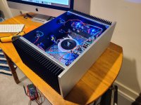
[h=The Project]%1[/h]

Do it yourself, Class-H power amplifier 1500WRMS @ 2ohms

[h=Introduction]%2[/h]

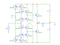
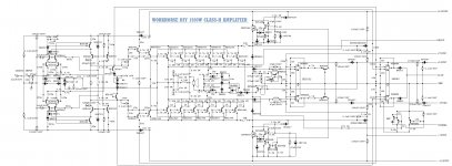
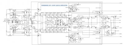
Its a Class-H amplifier with following features:

1: Fully complementary symmetry input differential with Cascode loading.

2: CE-CB Cascode VAS for wider bandwidth.

3: 2 Step rail switching with controlled slew for minimizing switching noise.

4: Triple EF output stage for high damping factor and ease in 2 ohms load driving.

5: All set of required basic professional protection circuitry.

6: Almost Half the heat dissipation of same wattage class-ab amplifier due to Rail Tier Switching and excellent handling of reactive loads.

[h=Goals]%2[/h]

Goal: To design a reliable amplifier with professional standards.

Result: All design goals met.

[h=Specifications]%2[/h]
border="0" cellpadding="2" cellspacing="0"
|-
| class="tcat" | Name
| class="tcat" | Description
|-
| Voltage Gain || 26dB
|-
| Full power Bandwidth || 20-20kHz
|-
| Power output || 1500WRMS @ 2ohms
|-
| Input Sensitivity || 4Vrms @ 8Ohms
|-
| S/N Ratio || 100dB
|-
| Peak Consumption || 4400VA @dual channel @ 2ohms continuous music operation
|-
| Idle Consumption || 110W
|-
| Harmonic Distortion || 0.05% THD [FPRL]
|-
| Load Impedance || 2 ohms minimum
|-
| Slew Rate || 33v/uS
|-
| Stability || Unconditionally stable with all known real world speaker loads
|-
| Output configurations || Parallel/Stereo/Bridge operation
|-
| Damping Factor || >1000 @ 100hz


[h=Additional Features]%2[/h]

* Thermal shutdown
* DC Fault
* Muting
* Short Circuit Protection
* True Clip Detection
* Signal out
* Fault Status

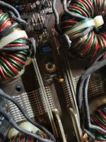
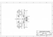
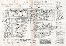
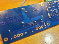
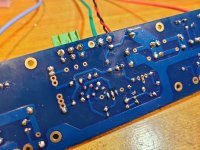
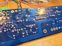
[h=Schematic/Blueprint]%2[/h]


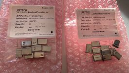
[h=Bill of Materials]%2[/h]

There is no BOM just yet. Will be added later.

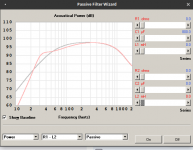
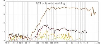
[h=Simulations and Analysis]%2[/h]

<Embed the images for your simulations here along with descriptions for each of them so people know what you're talking about.>

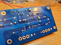
[h=Construction (Steps / Tips / Notes)]%1[/h]

[h=Project Files]%2[/h]

The files for this project are available in the attachments section at the bottom of the page.

[h=Other Notes]%2[/h]

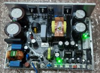
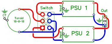
* Requires 2800VA transformer with following winding specs: 85-50-15-0-15-50-85 14A secondary.
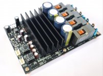
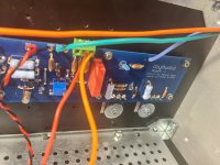
* PCBs should be printed with minimum 35micron and PTH is must as there are vias on the board
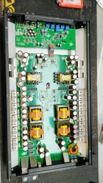
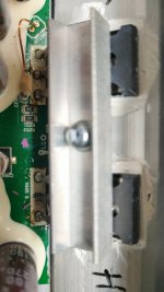
* PCB measures 37 X 12 cm (4.75 x 14.5 in)
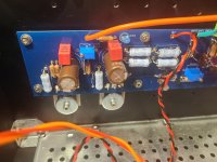
* Bias Pots: 10mV across emitter resistors of output devices corresponds to 30mA through each device, should be optimum

[h=Known Substitutions]%2[/h]

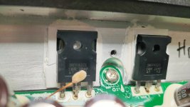
* You can use Genuine 5200/1943 upto 1.5KW or MJL21196/95 for 2KW


[h=Reviews]%1[/h]

No reviews yet...

[h=Build Threads]%1[/h]

Examples:

Have you built this project? If so, please add the URL to the thread that you started to show off your build.
  • URL to my uber build 1 thread
  • URL to my super dooper build 2 thread!!!

[h=Related Group Buys]%1[/h]
  • Thread 1234
  • GroupBuy😛SU

Attachments

Looking to build desk speakers with the tweeter I own.

Hi! I have been out of the hobby for a while. I am very happy with my primary system, but would like to also build a small system for on my desk (or hang on the wall above my desk).

However, I have no experience with near field builds. I do own these tweeters from a previous build: https://www.scan-speak.dk/product/d2008-851100/

The questions I have are, would they be valid for a nearfield build? What do you need to take into account in building a nearfield speaker?
Any known near field builds using these drivers?

Weird how, even when you are happy with your system, you start looking for places where you could build a second one 😉

Capacitor leakage current and resistors

Hello,
I am evaluating which resistance values can be right to balance two pairs of capacitors placed in series. An empirical formula hovered in an old forum thread, but to be more analytical from a capacitor manufacturer's guide they took into account the leakage current of C, that is:

Rba ≤ Rla (Vr)/10

where: Rba= balancing resistor value for the capacitor Ca and Rla= leakage resistance for Ca (at the rated voltage of C)

Now, I took a look varius brands of capacitors and from datasheet I noticed that for h.v. DC bus capacitors (that is, in my specific case 100uF/450V) the value for the leakage current is in the range from 100 to 600uA. And the present value is relative to some minutes from the applied voltage.

In particular, from i.e. Nichicon caps, there is a formula valid for a h.v. capacitors or: I(L) ≤ 3√(C*V) (in uA). With this assumption I found a I(l)=600uA, so Rba= 450/0.0006*10= 75k.
That seems to me a quite low value leading to have some heat dissipation. So I wonder if going to 100k or better 150k does no harm , since I don't know the I(L) for my brand of capacitors...Thanks

Aleph 5 - Q for Kit

Long time its now that i post me last Thread here.

Please i watch for a new Project, iam repair little Amp's but not like a pro, I watching meny time
for any Aleph 5, and i see kits on Ebay - China, please are this any possible way.... or what you
think from them, searching for any new Project, any will ask you some little help to go with
a Aleph 5.

Thanks for any possible help.
Regards
Mauri

The new "My Ref" Rev C thread

Since there is an active group buy coming to fruition, interest in this topic will be high in the coming weeks. While the original thread contains a LOT of information, it is exhaustingly long. Hence, this new thread for those of us about to depart on the "my audiophile LM3886 approach" adventure.

I have a question regarding transformer selection because this is new territory for me.

Suggested xformer is 24v, but the widest VA selection seems to be among 20, 22, or 26v. I will use this amp in monoblock configuration to drive the highs and mids of a speaker system with active xover between bass and mids/highs. The impedance of these speakers is slightly more than 4 ohms at its minimum. Should I select transformers that are slightly higher or slightly lower than the suggested 24v?

I'm looking forward to learning a lot more about building this amplifier and its optimum configuration.

Peace,
Tom E

Amp / subwoofer moving from 110V 60Hz to 240V 50Hz - possible?

Hi all,

Looking for a bit of advice. I have a Pioneer VSX-933 and a B&W ASW3000 running off my North American 110V/60Hz mains. I am moving to a country that has 240V/50Hz power. I really, really don't want to get rid of my B&W, and, to a lesser degree, my Pioneer. A stepdown converter will not convert phase; and while I can solder and have a vague concept about what this does to a motor, I can't quite grasp whether this is going to be a problem for my situation or not.

Would anyone be able to throw some light on this for me? I reached out to B&W but considering this sub is older than most of the people on Twitter, I'm concerned I might not get much from them on this 🙂 The VSX-933 is/was sold in Europe as well, so I don't know if it's just a power supply switch or not.

Thanks for any help!

6n6p preamp. Does it look ok?

Friend of mine got a power amp and wants a preamp, so I decided I'd build one with tubes.
I have a few 6n6p tubes around and I thought I'd put them to good use.
Also I have some 6n1p-ev and 6n2p-ev if they would be more suited for the job.

I made a sim of the schematic and seems ok. I made a DC-coupled cathode follower.
Did I leave something out? Any ways of improving this schematic?
The tubes operate biased about -4V, with 25mA and about 145V across them.

*** seems there's a problem with uploading files so I'll attach only the schematic, not also the sim file.

YhSZh6r.png

Humm on old amplifier

I have an old ARC SP8, that I now have working much better thanks to the clever folks on this forum 🙂

Last thoughts required to cure the hum that remains, I have go this a lot better with trial and error, but I can't seem to loose the last bit.
The below has worked, but still residue remains - any tricks or ideas welcomed

I have Shielded the DC heater cables
I have put in some additional steel plates as shields around the mains transformer to block the path towards the line stage valves.

I am going to replace the smoothing caps in the HT and LV supplies, but would love to hear any other experiences.

Thanks

RC4558P opamp replacement

Hi guys,

I have a Kenwood KT7500 tuner that has a noise(when it feels like it) coming from the opamp(traced the signal path before it and it goes away). My question is are there other op-amps that will take the place of the RC4558P that is there without modifying anything? When changing these, is there bias' that must be checked? Sorry, if I could get the concept of electronics into my head I wouldn't ask questions I guess. Thanks.

Passive Radiators with dynamic resonent frequencies

I have alot of questions about acoustics, both in car audio, high end home,. And exotic.

If I Invision the simplest passive Radiators enclosure, it's a tube with a passive at one end, and a driver at the other, int the shape of a u such that both passive and driver are colocated. If the tube is the correct length, such that length = length / speed of sound = a whole number multiple of the frequency being played. In this situation it will yield the best possible output and sound. But only at that frequency.

I am an engineer and a physics want to be,. But I can think of a number of ways to make rapid changes to the different properties of an enclosure and or the driver which would allow for the running frequency being changed, on the fly, each time the frequency of the output changes. I worked in nanotechnology alot,. And I'm certain that I could design such an enclosure. So I'm sure other have. If not, and anyone would like me too, I will. But if I am missing something that fundamentally creates a problem,. Ide rather someone tell me.

I would use some type of microwave structure which can be opened and closed nearly instantaneously to modify the length of the tube,. And a variable magnetic field to regulate the resent frequency of the passive.

Ben

AB International 713A crossover-pcb

Hello there;

I own some AB International 713A amps with built in active crossovers.
I want to change it from 3-way to 2-way like the model 712A.
Does anybody know or own a model 712A to give me some info on the jumper settings of that .
Seems like the crossover-pcb is standard for all models ,just the jumpers change.
Thanks in Advance;

Jorre

Attachments

  • front 713.jpg
    front 713.jpg
    706.3 KB · Views: 101
  • pcb 713.jpg
    pcb 713.jpg
    576.1 KB · Views: 100

Butchering an Antique

Hi,

I've decided to give an old GE radio an upgrade. I'm sure there will be some haters but, what I plan to do is rip out all the original components and install a Bluetooth amplifier and new speakers. As a starting point I've found some components at parts-express.com part 300-7128 (Speakers), and part 300-593 (Amplifier).

Here are my questions:
-How would you recommend mounting the speaker boxes to the inside of the radio?
-Would it be better to build a custom box within the radio to house the speakers?
-Would you use different components?

The opening is 14" wide x 18 " tall and there's about 18" depth to the radio.

Thanks for reading and commenting!

Attachments

  • Radio.jpg
    Radio.jpg
    363.8 KB · Views: 122

Aluminum PCB for sale

We have 3 PCB and PCB assembly factory located in Shenzhen, Jiangsu, Jiangxi separately.


link: PCBONLINE - Aluminum PCB Manufacturer and Assembler, EMS Service Provider

PCBONLINE’s aluminum PCBs have low thermal resistance and high thermal conductivity, which increases your module’s power output and lengthen its lifespan.

my email: Donna@pcbonline.com

You can send the Gerber and quantity to me to get fast quotation! of course we have cooperation with FedEx, you will get a very low freight from us.

The test of a 'Muscial' Sub.

Most of the members on this site are not my peers, nor do we share equal appreciation of music genres. There are many design and technical debates. However, the question, "What do you want your sub to do?" is rarely asked.

Home Theatre subs are generally 'minimum wage'; offer maximum: grunt, growl, rumble, or boom when asked and they'll earn their keep. Even and rock and classical fans don't require too much finesse and precision in the lower frequencies. One note often blends into another.

I was weaned on Jazz / Funk and cut my teeth on UK Garage. These genres differ to many others because the bass is the lead, it's where the tune is. In rock music the bass player is the butt of so many jokes because he's the talentless afterthought in the band - who cares if he misses a few notes?

My favoured genre requires quick, tonal, defined bass. I am blessed to have three home audio systems - some of which are better than others at playing 'quick bass'.

(1) It's not always the sub's fault. (Decay, volume of overtones).

(2) You should WATCH this guy while LISTENING - he's really good!!

Login to view embedded media

ESL diaphragm tension

Hi, I just finished my fifth pair of electrostatic loudspeakers. They are smaller than the previous ones which have much lower sensitivity, because they seem to leak bias. The newer models have smaller d/s as well (about 1.6 mm compared to the about 2.2 mm of the previous stats).

One panel experienced a problem with static stability as the diaphragm sucked to one of the stators on one panel. I attached a new diaphragm with much higher tension: I use duct-tape to tension the mylar, and the first attempt resulted in a very low tension. I didn't measure it, but the mylar surface has dimensions of 23 x 130 cm and one panel had a resonance frequency of 43 Hz, the other of 65 Hz. The panel with the lowest resonance experienced the stability problems, so after a second attempt I managed to increase resonance frequency to 86 Hz!

Problem is, that low frequency extension is limited now on the 86 Hz panel. So if I'm correct there is a relationship between sensitivity and static stability: the higher the resonance frequency, the higher the mechanical tension of the diaphragm, the higher bias can be applied, but the less low frequency extension, but physical excursion of diaphragm is less with higher resonance frequency.

Right now I think the best option / compromise is to get a high as possible mechanical tension in order to get maximum static stability and sensitivity. Sensitivity of my new stats is around 86 dB @ 1 meter @ 1 kHz @ 1 VA.

They are limited in low frequency output as they fall rapidly at 65 and 86 Hz respectively. But compared to my boxed transmision-line floor standing loudspeaker it turns out this isn't as big as a problem as I would think. But in order to get more low frequency extension I would need to make the diaphragm dimensions bigger, which leads to my next question: how do other stat builders get enough low frequency extension? Like Quad: the ESL-989 seems to have a resonance peak somewehre around 55 Hz:

https://www.diyaudio.com/forums/planars-and-exotics/361665-quad-esl-resonance-damping.html#post6377852

The stators seem to consist of 6 seperate panels per channel:

Quad ESL 989 Modifikation - Counterweight Tonarmgewicht Dual 704 Zarge Rahmen Quad ESL 989 Modifikation Clockwork FineNeedle AT20SLA ADC 10E Tesla geschenkt gratis 1500 km

Dimensions of the 989 are: 52" (1335mm) H by 26" (670mm) W by 12.25" (315mm). So 1 section (out of six) would measure at most 22 x 67 cm, much smaller than my panels which measure 23 x 130 (diaphragm dimensions).

I would expect low output after resonance frequency, and the sections of the quad 989 are about half in size of my panels, but resonance frequency of the complete panels is still lower (55 Hz?) than my panels. I'm wondering how this is possible?

Info/Help Request

I've been curious about the Accuphase DC-91's SFA/Sample Frequency Accuracy function.
From the brochure:

SFA.jpg

I almost never get Level III. I use a PC with foobar as source. Level I or Level II for my music library. Got 1 Level III read from toslink out of my tv and watching The Expanse. Yet it never holds Level III as i replayed the episode and only get Level I. I currently use an m2tech hiface evo usb to spidf for it's ST optical, but i borrowed a Mutec MC-3+ and at first connection-the SFA read Level III, then i never saw it again as everything read Level I or Level II as usual.

Would anyone happen to know if by manual override-it means internally?

When i hold down the SFA button and press volume up at the same time, the display will change to 'on' and when i hold the SFA button and press the volume down at the same time, the display reads 'oF'. There is no change in sound and no change in Level I or Level II read. I don't know what is being turned on and off. Logically i first assumed, i turn Level I off, then Level II off and Level III would be ON, but that means i would have to happen upon a rare Level III reading to turn ON while the others OFF assuming oF means off in the first place. With Level I and Level II OFF, my music still displays Level I or Level II.

I don't see any other button options to manually override to Level III clock.

30w Jean Hiraga Power Supply Design, one large capacitor or several?

Hi All

I've been trying to finish the amplifier project for a year now, one because of cash flow and the other because i became a father some 10months ago! This put the project at a major halt!

Since then i have been slowly buying parts and i am just about ready to get this thing built!

Im planning on building a dual mono amplifier in one massive chassis, so each channel has its own power supply

So far i have:

4 Full wave ultra fast rectifier boards to do dual bridge rectification for each channel.

2 Selectronic R core transformers 500va 2x24v (i dont know anything else about them except they are new and they were such a bargain) These things are big and weigh quite a bit!

I also invested in a pair of lundhal LL2733 chokes as i want to do a CLC power supply of some form.

Next on my list is the capacitors, which have come down in price since last year.

I know that around 1.2F is what is common i was thinking perhaps each channel can have 0.6F each or even 1F each if i want to go big.

It actually works out cheaper for me to buy one large capacitor like a 0.75F cap instead of 3 x 0.22F capacitors. Does this make a difference? I think i read somewhere that a group of capacitors has better ESR? please correct me here.

My thoughts were i could go first cap something like 0.1 or 0.2F capacitor then the 0.75F capacitor. Or 3 x 0.33F for each channel. Also should i go 35V or higher like 40-50V. At a guess with the rectifiers, choke and capacitors my rail voltage shouldn't exceed 35V.

I am so new to this, and this will be my first major power supply build. I have read many threads and looked at examples but thats as far as my knowledge goes.

I wish i knew how to calculate and design this sort of thing, i have know idea whether i need snubber capacitors, another resistor in place etc. Also not sure if i need a soft start, read and been told i may not because i'm using an R core and a choke.

Would i benefit from using a EMI filter? Also do i need a star ground?

Ive attached a drawing of my attempts to start designing the power supply, if someone could assist and guide me it would be greatly appreciated.

Just want to know the best route and design i need, so please pick it apart, curse me and correct me!

As i said i would love to understand what i am building and why, if there is anyone in north london that could help, sit down with me and teach me that would great, i would even pay for this service or buy you a really nice drink.

Clearly i am not making my life simple, but i thought i might as well go in large and hard or go home!

nCgQ1bB.jpg

Taming rising tweeter response

What is the simplest way to tame rising tweeter response? I have seen that adding a series resistor to a tweeter can raise the response as frequency increases but what about if you have a response that rises with frequency? I am sure that a zobel would help but how about a simple resistor in parallel (assuming lowered Z and increased power draw are acceptable) would that in itself provide some reduction of the slope?
Projects by fanatics, for fanatics
Get answers and advice for everyone wanting to learn the art of audio.
Join the Community
507,781
Members
7,888,188
Messages

Filter

Forum Statistics

Threads
406,225
Messages
7,888,188
Members
507,781
Latest member
Ronny2001