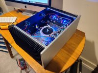
Hi all! I have been lurking here for about 6 months as I've been getting ready to do an Aleph J build, and I finally got to work on it this week! I am using a matched set of jfets and mosfets as provided by the current available set.
I just hooked it up to a source and speakers for the first time - one channel seems to work, but the other is emitting only a hum. Though I haven't cranked the source, I fail to hear any semblance of the input signal in this channel.
Voltage reads around 23V on power supply, I haven't looked too much more at that as one channel is functional.
I was able to bias and set DC offset for both channels and at time of test both were running at 400mV bias and 0.1ish offset. Both heatsinks were around 152 F.
This is my first build and I don't have a ton of electronics experience, so thanks in advance for any guidance! I am not an expert solderer and can definitely recheck those connections, but I was hoping there were some measurements I could make before disassembling that may narrow things down. The channel to the right when looking at the amp is the faulty one.
Attachments
-
 20220116_055151.jpg370.4 KB · Views: 147
 -
 20220116_055151.jpg370.4 KB · Views: 166
 -
 20220116_055140.jpg424 KB · Views: 158
 -
 20220116_035145.jpg535.9 KB · Views: 158
 -
 20220113_171803.jpg496.1 KB · Views: 166
 -
 20220113_171759.jpg455.3 KB · Views: 143
 -
 20220113_171748.jpg435.9 KB · Views: 141
 -
 20220113_171745.jpg468 KB · Views: 150
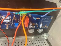
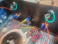
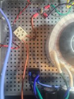
Thank you both for the replies and all the work you have put towards these amps and this site! Here's some additional pics of the PSU and input side - a source I was following said that for XLRs the ground pin could be grounded to the case. I tested for continuity from the GND on the board to the pin and it came back good.
Attachments
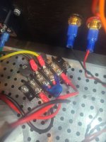
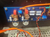
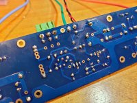
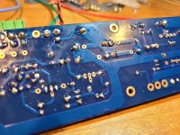
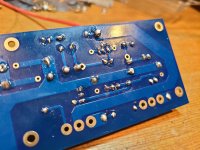
First carefully visually compare both channels and see if you can find any difference
between the good one and the bad one. Look at each part and each connection,
and verify that each connection and part is correct, including the resistor values.
Then compare the DC voltages at all of the circuit nodes.
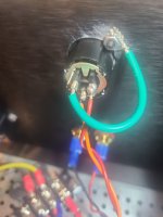
I don't like the soldering on the XLR pins at all. The yellow wire looks especially suspect.
Desolder all of them and redo it. Most of the photos are too blurry to see much, though.
between the good one and the bad one. Look at each part and each connection,
and verify that each connection and part is correct, including the resistor values.
Then compare the DC voltages at all of the circuit nodes.
I don't like the soldering on the XLR pins at all. The yellow wire looks especially suspect.
Desolder all of them and redo it. Most of the photos are too blurry to see much, though.
Last edited:
Pin 1 of the XLR socket should not be connected to chassis safety ground. It should be connected to the negative IN on the Aleph J board. For single ended input (RCA), the negative IN can be connected to Ground on the Aleph J board. Or if a RCA to XLR adapter is used the connection may be made within the adapter.
")
I am curious about this though. My current setup is pin 1 to chassis ground, pin 2 to +in, and pin 3 to -in. It appears to be working, though to be honest I don't have great understanding of xlr and just went with that for completeness and am using an RCA to XLR adapter on the outside of the chassis. Should I switch it around or am I OK?Pin 1 of the XLR socket should not be connected to chassis safety ground. It should be connected to the negative IN on the Aleph J board. For single ended input (RCA), the negative IN can be connected to Ground on the Aleph J board. Or if a RCA to XLR adapter is used the connection may be made within the adapter.
Your pinout is correct.I am curious about this though. My current setup is pin 1 to chassis ground, pin 2 to +in, and pin 3 to -in.
Attachments
Last edited:
Whoops, I meant to say connect pin 1 to Ground on the Aleph J board, and not to chassis ground.Pin 1 of the XLR socket should not be connected to chassis safety ground. It should be connected to the negative IN on the Aleph J board. For single ended input (RCA), the negative IN can be connected to Ground on the Aleph J board. Or if a RCA to XLR adapter is used the connection may be made within the adapter.
it makes usually
try it - if you don't have buzz, you can leave it temporary connected to chassis
as reminder, XLR pins:
1-GND
2-positive hot
3-negative hot
if you think of using SE, temporary or for good, connect together pins 1 and 3 ditto on XLR, so you can use pair of wires or single coax to route signal to pcb
try it - if you don't have buzz, you can leave it temporary connected to chassis
as reminder, XLR pins:
1-GND
2-positive hot
3-negative hot
if you think of using SE, temporary or for good, connect together pins 1 and 3 ditto on XLR, so you can use pair of wires or single coax to route signal to pcb
What ZM said.
It's best to have the signal Ground wire twisted together with the negative and positive signal wires all the way to audio ground on the audio board for minimum loop area and minimum noise pickup.
The chassis routing of signal Ground also passes through the CL60 ground lift thermistor before it reaches audio Ground.
A question, ZM: If pins 1 and 3 are connected at the XLR and only two wires go the the board, then neg signal input circuitry at the board is not grounded. Is that ok for ok for single ended input? If three wires from XLR go to the board, then the neg signal input circuitry is grounded.
Last edited:
- Home
- Amplifiers
- Pass Labs
- Aleph J Troubleshooting