Volume control options for tube preamp

Can we run through the common options for volume control on a tube preamp giving pros and cons?

Examples:
  • log volume control
  • fake log using linear taper with a resistor, and best resistor values
  • stepped attenuators of different constructions including shunt types
  • TVC and autoformer
  • other types

What are you using, how did you make that choice, and how do you like it?

FS tube amplifier PCBs of my own design EL84PP EL84SE and PSU boards support included.

Hey Builders!

I have designed some PCBs for tube amplifiers. And have ordered some of each design.

I will be selling these here, for 7.50USD each. Will provide nearly unlimited support over telegram if you purchase some.

Shipping at current PostNL rates. Which are about 12 USD for a 400Gr parcel to North America, and lower for Europe.

I can also supply parts kits for the electronics, and help you source parts.

Cheers, V4lve Lover.
  • Like
Reactions: TR00 and kodabmx

DML Patents and Licensing

Hi All,
Anybody here have any knowledge regarding the current state of the art in DML/BMR products?

Specifically, if I want to bring a DML-based product to market, then do I assume that the patents and licensing fees are included in the drivers that I purchase from any arbitrary manufacturer, or do I need to pay licensing fees to some schmo for the hard work and I.P. that I've put into my panel designs?

Mods on Bryston 10B Crossover

I just acquired a Bryston 10b after a long search for an electronic XO. I wanted analog, high quality and discrete components. And there aren't a ton of choices.

Once receiving it. I downloaded the schematic and popped the cover. Right away I notice that there are 8 100uf electrolytics directly in line right at the outputs. There are also some small ceramics in the signal path right before the high pass resistor array ( I presume the switch shown in the top right is the 6/12/18dB selector labeled N1/2/3)

It is the standard model, not the Sub. it is the balanced version.

I'd like to upgrade whatever components I can to increase performance. Aside from the components I noted, I'd also be grateful for other suggestions.

Part of the challenge is this unit is only about 2" high, and those electrolytics are on top of a board so there's limited room. One option I considered was to move the PS board to an external box, which would open up room.

Any and all suggestions would be greatly appreciated!

Attachments

An Improved Array

I had some time off work, so I've been trying to decipher how the Beolab 90 works. I'm looking forward to hearing it again in a couple weeks. (At CES.)

While studying the patents, I stumbled across an interesting one from Enrique Stiles. In this thread I'll take a stab at describing it.

Mr Stiles' patent is based on the work of Philips. About 35 years ago, Philips patented a novel array named 'the Bessel array.'

The concept of the Bessel array is very simple:

In a conventional line array, the elements sum constructively at low frequency, and destructively at high frequency. Specifically, they'll sum destructively when the frequencies reproduced are shorter than the center-to-center spacing, and they'll sum constructively when the frequencies reproduced are longer than the frequencies reproduced.

The reason that this happens is due to phase and amplitude. At low frequencies, all of the array elements are in phase due to the long wavelengths. At high frequencies, this is no longer true, because the wavelengths are so short. And this gets worse the further you go off axis. (Due to the phase differences.)

So the Bessel array addresses the phase and amplitude issues in two ways. First, two of the five elements are driven with a reduced amplitude. Second, the phase of one element is flipped.

The net result is an improvement in the off-axis response, at the expense of overall amplitude. The overall output of a five element Bessel array is equivalent to the output of a two element line array.


More info can be found here : http://www.diyaudio.com/forums/multi-way/38523-bessel-array.html

Arguably, nearly all attempts to improve array performance are based on attempts to manipulate the phase and amplitude of the array elements. For instance, 'shading' manipulates the amplitude. CBT arrays manipulate phase via physical placement, and also 'shade' the array. IMHO, 'log spaced arrays' are a clever method of shading an array without modifying the voltage.

CLRE0P8.png

Here's a comparison of a conventional five element array, versus a five element Bessel array. Note the improvement in off-axis response, at the expense of overall output. Data is source from Mr Stiles' patent, #US20060018491 A1

P3 Adjustment for the average Hobbyist

After some very recent conversation on the "BA3 as Preamp" thread, several have obtained the 212 interface to use with ARTA or other program is setting of P3.

Some are as lost as I am, others not quite so much. In an effort to enable the average guy to set P3 to one's benefit, (or at least make both channels symmetrical) this thread was created.

Most of those envolved with the discussion either have, or are getting this device:

Focusrite Scarlett 2i2 | Sweetwater

Also, a Tascam unit is listed that would also be appropriate. Some have done this and are going to show how they hooked it up, the rest are flying by the seat of the pants.

This discussion began on the "BA3 as Preamp" thread, post numbers #1298-1313.

Please feel free to join comment inform etc.

Russellc

DIY Turntable plans?

Any plans out there for a DIY turntable? I was thinking it'd be fun to buy some components and build a plinth for them. I'd buy a tonearm, bearing, motor, and probably also a large platter, and then build a handsome plinth to unite them all. But I'm not sure where to begin. I see lots of cool builds online, but many of them seem largely developed entirely by the builder. I lack the science/math skills necessary to design my own system, but if there were some plans out there, I could follow them.
Does such a thing exist?

Tune passive radiators with specs unknown

Hi folks,

I'm new here and opened this thread because couldn't find directions for what I'm looking for.

I want to build a bluetooth boombox-style speaker with two 4" drivers and two 4" PRs.

I went for PRs after modeling for ported speakers with my drivers' specs in winISD, the results with ported was an enormous necessary internal volume for anything under 60-70 Hz.
The thing is I only have access and money for chinese PRs (like these https://aliexpress.com/item/4000203225569.html) but they have no T/S data or any specs for modeling.

Is there some empirical way I can test/measure resonant frequency for tuning it, like a variable sized box or something, and how could I do measurements with it?
I have no pro equipment for measuring.

Any insights would be much appreciated.

Toroid Transformer - Dual 45v Secondaries 600VA

Primary 1 - 0 - 120VAC & 0-120VAC

Secondary 1 - 45VAC -0 & 45VAC -0 (6.6A each)
Secondary 2 - 14.75VAC - 0 - 14.75VAC ( .75A)
Secondary 3 - 17-0 (.2A)

With all hardware. $40 + ship?

I have 2 available...

Pick up in West sub of Chicago or ship

Attachments

  • PXL_20201204_180353648.jpg
    PXL_20201204_180353648.jpg
    685.5 KB · Views: 513
  • PXL_20201214_022735100.jpg
    PXL_20201214_022735100.jpg
    627.2 KB · Views: 501

Hypex Subwoofer Plate Amp

Hypex UCD180LP x2 (Bridged) and SMPS400A180 Power supply Subwoofer plate amp. Specs say 700 wpc @4 ohm.

Works great, but cannot work for what it was intended on project, so up she goes.

These are pro-audio Electrovoice ELX118 plate amps.

$250 + ship from West sub of Chicago?

32hz - 130hz

Attachments

  • PXL_20210605_154547334.jpg
    PXL_20210605_154547334.jpg
    995.9 KB · Views: 983
  • PXL_20210605_154554406.jpg
    PXL_20210605_154554406.jpg
    975.9 KB · Views: 905

Amber 3501 analyzer + parts

I'm selling my Amber 3501 analyzer. I used this analyzer quite a bit 4 - 5yrs ago, but I've been using an Audio Precision Sys 1 since then and this Amber just sits around gathering dust any more. I went through this analyzer back about 5yrs ago, the upper analyzer/oscillator pcb had all of the tantalum caps replaced with new 35V rated tant's and the e-caps were also replaced. I also replaced the tant caps with 35v units on the lower input pcb as well. The power supply board on the rear panel received new caps also.

This analyzer didn't come with the freq meter originally. I purchased a used unit off of Ebay that had the freq meter on it and swapped it onto this 3501. The freq meter is very nice to have on these old analyzers because it makes it so much quicker and easier to see what freq you're testing at. I tested the Freq meter back when I installed it to find out what the upper measurement limit of of it was and it will measure freq's up to around 1MHz. Also this analyzer came with the CCIR filter board in it. I wanted the "A wgt" filter so I built one and installed it in the optional filter location. I'll include the CCIR filter board in case you wanted it, but the A-wgt filter is still in place. I picked up a couple of NOS CLM-8500 opto resistors that are used in the tuning section of this analyzer. I installed one of them, I'll include the second one with the purchase. Its still sealed in its original pack.

I added a small cooling fan to the rear panel. I found when using this analyzer for lengthy periods that the covers would get extremely hot. After a few hours of running very hot the analyzer's performance would suffer and the THD readings would rise up from -102 to -103dB up to around - 97dB or so due to the heat. In the early units the power supply was in a separate box, but in the later production models like this one they put the power supply into the main case and eliminated the external power supply. This analyzer has very poor ventilation slots in it and doesn't cool well, when coupled with the internal power supply it gets hot when not actively cooled. Adding the cooling fan completely corrected that situation, this unit now runs at room temp all the time as long as the cooling fan is running.

Also this unit didn't have the battery in it when I got it. I added the wire harness and put a small UPS battery into the unit. I just put a different battery into it a couple of weeks ago that seems to be holding a good charge. I fully charged it and then let the unit sit for 20 min running on the battery and it was still showing about 50% of the "Batt OK" range on the meter. I think you can probably get a good 30min on this small battery without running it down too far. You could put a larger battery in and probably get well over an hour of battery life out of it. This is a great option to have in order to eliminate ground loop issues. Being able to unplug the 3501 from the wall while testing can eliminate a lot of noise issues on gear sensitive to ground loops.

This 3501 has a bit of meter fluctuation when operating and its most visible when operating in the -100dB range. If you run a 1kHz loopback test with the 30khz low pass filter active you'll get .0007 - .0008% THD+N. So the needle fluctuates typically within that range in the -100dB range. Activating the 400Hz HP filter will further drop the 1kHz THD to about .00065 - .00075%. When running a 20kHz loopback test this analyzer will show .00125% THD+N with the 30kHz low pass and 400Hz high pass filters active. Reading that in the -90dB range shows minimal meter fluctuation.

This is a very nice meter that's had most of the maintenance work performed on it and is ready to use.

This 3501 does NOT have the IMD option.

Price $375 + shipping + paypal (I also accept Zelle) I'll only ship to the continental US.

Attachments

  • Front.jpg
    Front.jpg
    760.3 KB · Views: 194
  • PXL_20220910_185448408.jpg
    PXL_20220910_185448408.jpg
    594.3 KB · Views: 247
  • PXL_20220910_194348156.jpg
    PXL_20220910_194348156.jpg
    627.1 KB · Views: 183
  • PXL_20220910_185624755.jpg
    PXL_20220910_185624755.jpg
    538.1 KB · Views: 167
  • PXL_20220910_194710094.jpg
    PXL_20220910_194710094.jpg
    528.2 KB · Views: 179

QUAD 303 style output triples

Trying to understand the output stage, I have tried simulating the two triples as complementary sets and find that the npn-pnp-npn and pnp-npn-pnp arrangement is much worse behaved than the pnp-npn-npn and npn-pnp-pnp
The second arrangement, left hand side of the schematic has a lot less hard switching and high order distortion.
The original 303 used both structures to get away with an all npn output stage, but it was unbalanced with significant 2nd harmonic before feedback

Attachments

  • LTspice XVII - triples.png
    LTspice XVII - triples.png
    11.3 KB · Views: 144

6.3 filament from 5vac winding

Hi All,
This is my first post to a forum so please bear with me.I found this idea in the book Tonnes of Tone by Kevin O'Conner and thought I would try running my 3 preamp tube filaments on 6vdc to see if it made a difference in the hum of the amp.The article stated it could run up to 5 preamp tubes on a 5vac 2amp winding.I am putting it into a tweed chassis and with it being a little tight I changed the bridge rectifier from a KBP602 to a BR104.I also changed the transistor from a 2n3005 to a TIP3005G.the circuit runs at 6.28 vdc with no load but drops to 4.2vdc when I connect a .45amp load.Any ideas on the problem would be greatly appreciated.Please see the attachment for the schematic.Thanks,Tom

Attachments

  • P.S.Board.jpg
    P.S.Board.jpg
    385.4 KB · Views: 769

Linn LP12 Trampolin Kit

Hi, everybody out there,

this is my first post on this forum. I'm using a fully equipped LP12 as a main source for listening. This means: LP12, Aro, Armageddon, Cirkus-Kit, Trampolin-Kit, Benz Ruby 3 Cartridge.

I'm lookin for your experience with the Trampolin Kit. Is it useful, if one has a really rigid stand? Does it better the sound... or not...:xeye:

I'm very keen to read about your experiences.

Have a nice time.

Wolfgang

Re: Linn Cirkus bearing set

Re: Linn Cirkus bearing set

I wish to change my Linn LP12 to Cirkus but the Hong Kong dealer is selling me a full set that includes the spring, subchassis, arm board etc. Why do I need these since I already have them in my turntable? Is there a place that I can only buy the Cirkus bearing?

Is there an online source that I can buy Linn accessories at a reasonable price?

suggestions on how to dissipate heat on a snap-in capacitor that's NOT soldered to a PCB

Hi everyone,

I just read that capacitors produces heat and this heat needs to be dissipated. When installed in a PCB, this is not a problem as the copper traces can act as a PCB.

I want to do a simple unregulated power supply using point-to-point (think tube wiring). The most inexpensive capacitor I've seen within the capacitance required/desired is a snap-in.

Any ideas on how to dissipate the heat?

The capacitor will be mounted directly to the bottom metal plate of the chassis using clamps (with the capacitor "hanging" upside-down).

some ideas/thoughts that comes to mind:
  1. Perhaps I can use a heatsink grease between the "top" of the capacitor and metal plate to dissipate the heat? or maybe the copper wiring soldered to the pins is enough to dissipate the heat?
  2. My assumption with screw mount caps is that with a screw capacitor, I can use a copper plate to act as "PCB tracks" which would then act as heatsink. It would be easy to attach the copper plate to the capacitor because I can use a screw.
  3. Maybe there's no need to be concern at all?
Thanks in advance.

PS. I have not used snap-in or screw capacitors before. my experience is limited to using soldering (<4700uf and less) caps to PCBs.

switch mode power supply for good amplifiers

OK- I know the answer - don't. Good old power supplies are better, easier to work with, and can deliver all the clean power you need - in line with the experience Nelson Pass convey . And I am not doubting that this works - I have had a class A amplifier that consumed 500 watts, and I had absolutely no complaint with the sound.
However, I am living in Europe, and we start taking energy consumption seriously. So my question: Has not one single company specialised in making decent switch mode power supply for hifi? Benchmark claims that it is possible with their power amplifier. I am not talking about only using them for Class D amplifiers - is it a dream to use such a thing for one of the smaller Pass single ended class A ( such as 20watt). With the efficiency they have, a dream could be to have the good sound with only the use of what an old light bulb might consume.
Is this just a dream? I am not talking about a DIY thing, but a power supply someone made for DIY'ers.
Please tell me if this is just a dream - but I would be even more interested in coming to know some solutions that might be - maybe not perfect, but acceptable.

Indel transformer any good?

Hi,

Anyone has experience with Indel toroidal transformers? Are they any good? No buzzing?
I need a pair of 300VA 30-0-30V and these are very unexpensive - to good to be true? http://www.tme.eu/en/details/tst300w_2x30v/toroidal-transformers/indel/tst300016/

What about these from Talema? 55174-P1S2 TALEMA - Transformer: toroidal | TME - Electronic components

Should I buy any of these?

Thank you.

Using a passive preamp with icepower 50asx2se?

Hello folks, Pardon my noobish question. However Im building a icepower amp based on the 50asx2se. I would like to have volume control on the Amp but not sure what direction to go in. I was wondering if using a passive preamp such as the Nobsound NS-05p between my Dac a music fidelity V dac II and the power amp is a wise choice? Im told the input impedance of the icepower is low appx 8k. Now I have a few optins for volume control seeing I use Roon and can enable DSP volume to the Source but prefer not to. WHats my best option? My other option was I often run my Yamaha CA-1000 vintage integrated as a preamp as well. CUrrently using it with a TPA3255 Class D chip board in that manner. Is there an off the shelf input buffer board I can buy to install in the ice amp along with a volume pot? Or what of these mentioned options are the best for my situation?

Low Power Subwoofer Modeling

Hi all,

Forgive me if some of this is not correct, I'm new to designing loudspeakers and subs but I'm really eager to learn more. I've been dabbling with modeling software for about a week now and playing around with various drivers and enclosures to get a better idea of things.

The application is home theater with my primary interest, from a subwoofer duty being 20hz to 80hz. I'm not looking at this time to hit reference at 15hz or less or anything.

Anyhow, I got really interested in the awesome VBSS design (by MTG) and then went down the rabbit hole of looking for ways to build either efficient or sensitive speakers, or both really, and then use DSP to limit the driver. So I started modeling with inexpensive drivers in various cabinets and came up with my own variation of the idea with similar hardware, but instead of using high powered amps, I'm looking at it from the perspective of... could this run off 50 watts at 8ohms? This makes amplification a breeze. To build SPL, it would be done with several units. This may be flawed thinking, so please, let me know where I'm falling off the cliff if I am!

Here's what I'm currently thinking about and modeling:

Slot vented MDF based enclosure, 24" x 22" x 18.45" with a 20hz tuning frequency. Net internal volume is 4 cubic feet (taking into account the driver displacement, etc, maybe a little more for bracing). I originally had a larger cabinet but the driver excursion was getting out of hand. 20hz is chosen to get that high SPL output with minimal excursion from the driver, so that the woofer is only really having to stress around 30~35hz with its excursion (if I modeled it correctly).

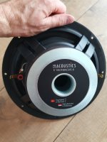
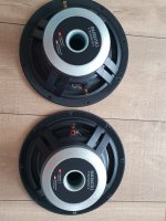
I'm modeling with the 
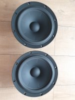
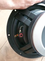
GRS 18PT-8 18" Pro Driver (8ohm). It's only $70.

SuperBudget18_4cuf_20hz.jpg


Here's the driver excursion relative to xmax:

I applied a few filters to control the driver. A highpass filter at 17hz. A lowpass filter at 200hz, but this could be at 110~120hz, it won't matter much as I will crossover. PEQ +15db at 20hz with Q of 0.75 to boost the near port output without asking the driver to have high excursion while doing it (I think?). PEQ -8db centered on 55hz with Q of 1.4 to smooth out the peak that was there and further drop excursion. The resulting excursion model in this box at the intended signal input is graphed below, so that the driver doesn't exceed xmax until well under port tuning frequency which I will cut off.

18PT-8_4cuf_20hz_ConeExcursion.png


For the slot vent, it's 1.0" x 20.74" x 29.74" in this enclosure to produce the 20hz tuning frequency, but also to limit air velocity from the slot at the intended input signal so that it doesn't exceed 18, conventional wisdom being this will eliminate the chuffing sound.


18PT-8_4cuf_20hz_AirVelocity.png


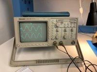
Those models and filters in place, the following is the SPL graph result.

This is where things get sketchy maybe. I'm modeling this based on a 10 foot distance from the driver face to the listening position and an input of only 50 watts at 8 ohms. I know this is nothing outstanding, but for me this is interesting because for just 50 watts, I'm looking at a nice curve to start working with from just one sub and only 50 watts of power that will be very stable to run. The goal will be to build several of these, 4 of them to start. So the idea is that if I'm getting potentially 96db at 20hz and up, when I add the 2nd sub, I could expect to be close to 100db at 20hz, and add two more and get closer to 105db potentially at 20hz, before room gain (sealed room).

I already have a miniDSP HD 2x4 that I use, so I would use that to align the subs and produce the summation virtual sub and then EQ that for a gentle house curve, based on whatever the 20hz performance ends up at.

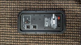
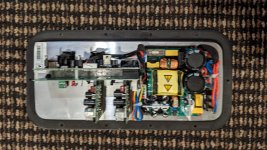
I already have an AudioSource AMP100 amp that does 50 watts into 8ohms, two channels, with a nice big power supply. These are inexpensive and pretty solid. I could add another for the 2nd pair of subs. I probably could get way cheaper amplifiers for this, but I'm not certain of quality in tiny class D amps around 50 watts into 8ohms out there with good quality output down to 20hz. I'm totally open to suggestions if you have them!

So end result would be 4 of these enclosures, each running at 50 watts max, for a very low total power draw running full tilt at all times if wanted, stable. Again, from the standpoint of 10 feet distance to the subs (they would be in a sealed room 10 feet from the listening position area) in the home theater room.

18PT-8_4cuf_20hz_SPL.png


If this is modeled properly, and will work (I have my doubts, which is why I'm asking!) the break down is:

Driver x 4 at $70 each, so $280
MDF, glue, screws, terminal binding posts, typical wire, x 4 - $200
Amp x 2 at $150 each, $300

About $780 for this project, unpainted. I would probably just black paint it matte or duratex type look, utilitarian.

Do you all think this is plausible?
Are the models ok or is something horribly wrong?

I do realize there are limits here, and that asking this system to do more than its max is not going to go anywhere. I modeled it for its max use and distance in the room for its purpose.

Any input appreciated.

Very best,

Bought a TAS5630 and instantly killed it - Chance for repair?

Hey people,

no excuses, don't know how I managed to do this, but I connected the 12V line to the amp with reversed polarity (yes, it's even printed on the pcb not to do this). While waiting for a suitable smps, I tried the amp with my bench psu which could deliver 50V, but only around 100VA, and everything went fine. As the smps arrived, I made everything fitting in the case underneath the sub, and installed two 120mm fans for an appropriate airflow, also. This was quite some work to do, including many hours of painting-sanding-painting-sanding-pain... .

Whatever, I switched it on, and the 12V wire went up in smoke. As hope dies last, and the two green led's were still lighting, I connected everything correctly and gave it a 2nd try. I switched it off as soon as the small blue spark showed at "D2".

Ok, it's dead. But I don't want to bury it, if there is a maybe a chance to fix it. The problem, I'm not the worst with the soldering iron, but I'm just a mechanic.
The green lights still light when 12V are attached, and just by looking at it, I do not see burned or "exploded" parts. Just U5, a LM317G voltage regulator looks a little strange.

What could I Do, what could I try, to maybe save this amp?
I've got no oscilloscope, just a multimeter.

best regards
Jochen

Attachments

  • 02 300.jpg
    02 300.jpg
    23.8 KB · Views: 136
  • green lights.jpg
    green lights.jpg
    375.4 KB · Views: 124
  • TAS5630B.jpg
    TAS5630B.jpg
    573.3 KB · Views: 151
  • D2 1200.jpg
    D2 1200.jpg
    250.1 KB · Views: 135
  • U5 1200.jpg
    U5 1200.jpg
    306.9 KB · Views: 140
  • 01 1200.jpg
    01 1200.jpg
    430.7 KB · Views: 160

Any tips for designing/building low noise preamps ?

I have been working on a diy audio mixer based on ne5532 opamps with auxiliary output/input, panning and baxandall tone control.
Here is the circuit of one of the inputs:
in PCB.png

(+-12v supply, 100nF on each Vpin of the opamps) (this "input module" will be duplicated for each chanel I make and all chanels get mixed in other circuit).

I made the PCB and everything worked fine (except the tone pots where inverted whoops :spin:). However the preamp adds to much noise to the signal and makes it pretty unusable for instrument-level inputs.

The noise (hiss) gets amplified when i raise the gain. And gets worse When treble pot is boosted... It also has some hum but i think thats because i havent shielded it yet.
Maybe you, the opamp-gurus, could give me some design tips on how to improve signal/noise ratio on the preamp. Or modifications to improve the rest of the circuit??

3D Holographic Imaging?

I intend to make a similar post on the tube forum. I hope that is acceptable.

Hello! I am trying to decide what sort of preamplifier / amplifier to choose for my system, and I have heard that tube amps do 3D holographic soundstaging and imaging better than solid state. Is there any truth to this?

This 3D immersive holographic sound is my biggest priority for my decision here, so would I be better off with tubes? If so should I do tube preamp or power amp? (I would prefer not to do both, and ideally neither)

I don't like how inefficient tubes are, I don't like that you have to replace them all the time, I don't like that they heat up rooms. I know they measure poorly but I don't care about that really. They sure do look cool though

Anyways, I will do whatever it takes to get the most enveloping imaging possible, but my fingers are crossed this doesn't mean I have to buy tubes. What do you think? Thanks!

Carver TFM-25 help

I am trying to get a Carver TFM-25 up and running again but it keeps going into protection mode only when a signal is applied. I plan on doing modifications per order of a service bulletin included in the service manual I attached below but I need to sort out the main problem first.

I am looking for someone to shove me in the right direction of what to look for, I am more familiar with hollow state technology. Plus this amp's topology is different than what I am used to seeing.

Thanks

Tascam MH-8 Headphone amp

I have two Tascam MH-8 headphone amplifiers. One of them has some problems I would like to address. Generally, it is working but there are some issues.

The unit powers up and there is sound, aside for a couple channels with broken pots that I need to replace. The primary issue is a large section of the main board that looks cooked under 2 rows of 32 transistors each and a row of 32 resistors.

I'm assuming the problem is the transistors and not the resistors (180Ω 5% 3W). Is this a safe assumption?

The first row of 32 transistors alternates between C1815 and A1015, there are 16 of each. From what I understand, these are complimentary transistors.

The second row of 32 alternates between C2236 and A966, again, these are complimentary.

The other MH-8 has a much higher serial number to compare to. The main board on this unit is not burnt and 3 of the 4 different transistor types have different part numbers on this later unit.

All A1015's have been replaced with A1266 GR
All C2236's have been replaced with C3205 YK 743 KTC?
All A966's have been replaced with A1273 YK 805

After doing some research, all of these are legitimate replacements for their predecessors. The C3205 and A1273 are in a different package than the A1015 and C2236 which are in a TO-226 package. I'm not sure what it is. I can't find anything like it in any package charts I have looked at. Does this even matter?

Also, the newer unit has the exact same 3 watt resistors, same value and tolerance, this is largely why I am discounting them as the source of the problem.

While the unit does work, obviously something isn't right given the blackened board and it appears that Tascam realized this and substituted some of the transistors in newer units. While I'm replacing the broken pots I thought I would replace all or most of these transistors. Would it be a good idea to replace all of the A1015, C2236 and A966 devices with A1266, C3205 and A1273 respectively as is the case with the newer MH-8? Would it also be a good idea to replace the C1815's with new C1815's since they've probably been through hell?

One other difference between the 2 units in this area of the main board is another row of 16 resistors. On the "bad" unit, these are 1/8 watt 2.7kΩ 5% and on the good unit, they are 1/8th watt 2.7kΩ 2%. See R032 & R044 in both pics above. Should I change these from 5% to 2%?

Finally, if this is a good plan, how would I choose between KT and 2S variants of all of these transistors since apparently either is acceptable? I don't really understand the difference. For example, 2SC3205 vs. KTC3205.

I would appreciate any input on this

JVC AX 440 source select problem

Hello.
Amplifier JVC AX 450.
Impossible to select source.
Any red led on front panel.
On J108 pin 1 ....+14v ok.
Pin 2 ......-19v,not -14.6.
I think IC101 is dead.
All voltages for power amplifier are ok.
Relay click.

Need help.

Service manual
https://elektrotanya.com/jvc_ax-440bk_sm.pdf/download.html

Attachments

  • IMG_20220915_225723.jpg
    IMG_20220915_225723.jpg
    370.5 KB · Views: 92

WARNING: About the DUST!

Administrator really should make this thread a "sticky"

My "high-end" neighbor likes to bring me his new found treasures that require servicing.
It's not always a pleasant job of course.
And this one job I'm currently doing is the focus of this thread.

It concerns vintage equipment that has a known, dangerous, and deadly element known as Cadmuim.
It was used in many things as a plating on metal parts, and perhaps you've seen a white or yellowish powder on old equipment.
Chassis, speakers, and other components are all affected.
It MUST be CAREFULLY removed.
Cadmuim is as bad as Asbestos if you breathe it.
A mask, gloves, and eye protection is mandatory.
And it has to be done OUT-doors, carefully.
I won't go into the whole procedure, you can look it up for yourself.

This is a close-up photo of the 1964-ish Thorens TD 124 motor assembly on my bench that was seized-up but serviceable.
It's gonna be a messy job, most of the turntable's parts are also contaminated with the white powder too.

cadmium dust.JPG

Hifonics BXi 6000D - Drive cuts out

The Amp is working at the start, 13,5V 2,5A, then after some time the drive dies, consumption drops to 1,5A.

The 12V Regulator only put out 11,88V, the new one does 12,11V. That didn´t solve it. +/-5V is there and doesn´t go down as the drive dies.

I desoldered the Driver-Board and put new IC´s and transistors in. LM211, TL072C and LM293.

Still the same, it takes longer than at the beginning, where it shutdown after a few seconds.

What could cause this behaviour? The Inductor beads have around 1Ohm.

Did someone have this kind of failure in the past?

Thank you for your answers.

Design around the mini earthquake and lp210pa

I would like to design a portable boombox around theMini earthquake subwoofer and the lp210pa plate amplifier. I would like some feedback on the different ways to go about it.
1) feed the the plate amp a stereo signal and add 2 fullrange speakers to the output. I'm thinking some efficient smallish 4ohm speakers should be preferred as they should be better at high range frequencies and the mini earthquake takes care of the low range. Am I correct? No crossover needed as the amp has a lpf and a hpf that is fixed at 100 Hz 6 dB/octave
2) feed the plate amp stereo signal and use midrange woofer and tweeter to left and right output. So here I should go for 8ohm speakers and tweeters I guess and use a passive crossover between mid and tweeter. I'm guessing this would make the whole system less efficient so maybe not the best solution for a battery powered system.
3) feed the plate amp mono signal add midrange to left output and a tweeter to right output. I got this idea from the dinas speakers. I guess this would play louder I wouldn't get a high-fi stereo sound but I doubt stereo really matters when listening outside with around a campfire or such. Would need a crossover to the tweeter again.
4) other suggestions are more then welcome.

This would be my first project so I'd like to keep somewhat cheap and use the KISS method (Keep It Simple Stupid!). The sound doesn't have to be extraordinary but a nice sound should be good enough for the girls I go out with. I know my way around a soldering iron and basic electronic stuff but audio is kinda new to me.

EMI noise on an I2S DAC only with GPIO PSU

If I power from a Pi USB PSU my DAC is quiet and also so is the boot.
I am trying to power from a 24v PSU with a 5v step down on GPIO and tried all sorts of EMI filters, Wide Input SHIM from Pimoroni. Its EMI in fact you can almost hear the SoC at work with a background noise that often sounds like an old analogue modem.
Is it because on the same 24v DC that powers a 100 watt amp it creates a ground loop as at whatever stage I add EMI filters to the DC supply I can not seem to get rid of noise that seems to be generated by the Pi unless I use a seperate PSU for amp and Pi. Which sort of negates my idea of a neat single 24v DC supply to a small enclosure for the Amp and a step down to power the Pi. Tried linear regs, a couple of different bucks and the Pimoroni psu shim with emi filters from input to the dac to pi power input and still noise.
Take out the buck and with a standard Pi PSU powering the PI with the same 24vdc on the amp and all is lovely.
I am scratching my head really but thinking maybe the GND in the audio out of the DAC is creating a possible ground loop that maybe with the 2x PSU isolation doesn't exist. Anyone got any ideas?

Clock buffer - using NOT or logic gates for less distortion

I saw an interesting article on clock buffers - specifically the impact of opamps on clock skew and jitter versus using series of NOT/inverter gates. The article demonstrated that the NOT gates (perhaps due to being an opamp Schmitt trigger configuration?) having less slew and less jitter. The result is that a series of NOT gates performed better than an opamp as a buffer.

I'll try to find the article - IIRC it was a Texas Instruments article. However has anyone tried/used this?

Setting up a passive PA system

Hi,
I am new to this forum. I need some help setting up a PA system. I have tried to look for some decent info online but it generally for powered speakers etc. which I do not want to use. I have the following components.

Xenyx 16 channel mixer
BSS 966 EQ
DBX 234 xl crossover
DBX limiter (not totally required just yet but I think this is set up as insert but not sure)
Behringer NX3000
and a Wild Thang 200 amp lol
2 Yamaha 12 inch tops
and 2 sub zero 15" subs.

I have had connected many different ways. I think I want to run it stereo but I see the benefits of running mono. I am setting it up primarily for my sons band and as a party PA. Any links or advice would be highly appreciated. Thanks again.
D

Elektor's CD Buffer + low pass Filter PCL86/ECL86 (Haas) - Conversion to a Preamp ?

The main application of this unity gain buffer device is the reducing of harsh and crispy sound character of various cd players resp. D/A converters.
My idea is now to use this device as a unity gain pre-amp for driving long signal cables to mono power amplifier inputs.
The retrofit of a good potentiometer shouldn't be an issue.

The question is, what is the aim of the serial input capacitor which have only 22pF.

In the attachment the description of the whole project include schematics.

Attachments

Audible Noise Transformer Core

I have built a small, isolated DC-DC supply. It's basically a flyback with optically coupled feedback. The transformer is planar type, and runs primarily in CCM. The problem is that the core rattles, sings, at light loads - its audible and easily heard. The PWM chip has a light-load feature where it skips as needed....this is when the core rattles. Without skipping (either under a heavier load or fooling the chip with a high value current sense resistor), the loop is very stable, and the core does not rattle at all.

My ears are not great, but listening to the pitch seems to be at about the same frequency as the bursts during light-load. So - I'm pretty sure the skipping feature is causing the core to rattle away.

Does anyone have an idea on how to fix this?

1kVA transformer to 33000uF capacitors (and other high power suggestions)

thinking of getting a higher transformer rating 2 power both right/left channels (parallel LM3886s) because

  • cheaper (looking at mouser, the cheapest 1KVA is only $50USD more than 500VA)
  • lower footprint

Is there anything I need to be concern? and perhaps you have suggestions for these concerns?

Also looking for suggestions for recommendations for such high power supply. (example: like heatsinking the diodes)

Thanks in advance

A Karlson Compendium - Part One - "A New Approach in Loudspeaker Enclosures"

A Karlson Compendium - Part One - "A New Approach in Loudspeaker Enclosures"

John Edward Karlson (Feb. 4 1910 - Jan. 18, 1973) was: an inventor, radar engineer, patent holder and co-founder, along with the late Wayne Green,
of a loudspeaker cabinet manufacturing company, Karlson Associates Imc., Brooklyn New York, and best known for his first commercial cabinet (now known
As “K15”.). K15’s prototype was built and tested in the summer of 1951, and introduced to the public at the fall 1952 HiFi show at The Hotel New Yorker, which
featured many of the luminaries of that golden age of Hi-Fi.

K15 was designed primarily for co-axial and full-range speakers of 15 inch size, and 12 inch speaker adapters were available. K15 has been ridiculed, and
touted one of the worst loudspeaker designs in history. It’s claims of flat response to the nether regions of bass are not true. What is true is that its capable of
a “musical” presentation when used with favorable drivers and also capable of agile bass at high peak amplitudes with very little cone movement. That is not apparent
from a simple graph. Over a certain region, horizontal polars can be improved vs a direct radiator. and distortion often than compromised mid bass and bass horns of equivalent
bulk.

As Karlson’s first “Acoustic Transducer”s article states, the tilted baffle forms a wedge shaped chamber and the tapering in volume vs widening of the slot, less energy storage than with a box cavity. Also, the upward tilt of the baffle puts some of the treble lobes through a tapered diffraction slot.

The patent also states, the greater the baffle tilt, the worse
the effect upon transient response so for a given loudspeaker there may be an optimum cavity, baffle tilt, aperture taper, etc.

Also, the greater the baffle tilt, the more "reverb" effect.

K15, loaded with Electro-Voice’s 15TRX speaker, provided sound for a number of pavilion and exhibit including Disney at the 1964 through1965 World’s Fair.

To my knowledge K15 was produced basically without change other than minor port and shelf gap adjustments.

K15, btw, was not the largest regular production model. Karlson also had a K18 console with upper compartment for midrange and treble drivers/horns.

In the fall of 1954, a smaller model for 12 inch (and 8”, 10 with adapter boards) the “Karlson Twelve” was introduced. At that time it was known as the “Karlsonette” as there were only two models. This early “K12” had a reversible port panel, and three position moveable bar on the back panel to adjust the area of the rear shelf lowpass gap. A year later in 1955, the tiny Karlson Eight was introduced.

1956 brought the diminutive KR5 “Rocket” speaker which resembled a standard pyramid shaped metronome. KR5 became the inspiration for Karlson’s “Asymmetric Projector” speakers with supposed “clam” shaped dispersion pattern - - affectionately known now as “klams”. These projector speakers were manufactured both by Karlson, and under license by Karlson’s good friend, Jess Oliver.

In this part is the 1952 Audio Engineering Magazine article

(Since I cannot go back and edit after 20 minutes to make a good table of contents, I’ll present this bit of history first - then plans in the next segment for the “heritage” lineup of Karlson Ultra-Fidelity models. - Then, hopefully links for the other Ks including GregB's Karlsonator series, and many ongoing threads by XRK971)

Attachments

  • KARLSON 1952 1.JPG
    KARLSON 1952 1.JPG
    552 KB · Views: 2,449
  • KARLSON 1952 2.jpg
    KARLSON 1952 2.jpg
    393.3 KB · Views: 2,004
  • KARSON 1852 3.jpg
    KARSON 1852 3.jpg
    430.2 KB · Views: 1,773
  • KARLSON 1952 4.jpg
    KARLSON 1952 4.jpg
    410.7 KB · Views: 1,704
  • KARLSON 1952 5.jpg
    KARLSON 1952 5.jpg
    898 KB · Views: 1,692
  • KARLSON 1952 6.jpg
    KARLSON 1952 6.jpg
    951.1 KB · Views: 1,244

Suggestion: Add a new subforum named "DSP coding & software tech"

As the DSP based crossover and room correction became a standard configuration in professional monitoring speakers, And high performance DSP chips gives us a new way to do something beyond the digital filter of a chip DAC.I do believe that software defined DSP will be the future of audio. To carry on the dreams to build the devices which would exceeding the base level of audio industry, we may need a SPECIEL subforum for the one who is good at writing codes and algorithm.

At current forums, the DSP focused thread can be placed in loudspeakers-multiway if its a DSP Crossover powered active speaker; or it will be in the source&line - digital line level if someone made a project of DSP chip based external digital filter for the DAC. Or even it can be find in the PC based subforum if it was running on a PC software and then send the processed data to a DAC.

We need coding guys assembly HERE in a right place, for the future of DIY audio device.
  • Like
Reactions: dreamth

For Sale SB Acoustics SB23NBACS 45-8 2pcs NEW

I am offering for sale 2 pieces of brand new SB Acoustics 8 inch woofers SB23NBACS45-8. These are black aluminium 8 ohms. Spend one year in garage and that's all. Opened only to check whether they are ok and to take photos for ad here.

Never played, mounted to any kind of baffle or soldered.

Price for both 150 EUR or USD as they are the same now. Shipping within EU 30 EUR. Will accept buyer's courier upon previous agreement. For shipping outside of EU please get in touch.

Paid on PayPal.

Attachments

  • 20220828_145853.jpg
    20220828_145853.jpg
    359.8 KB · Views: 78
  • 20220828_145752.jpg
    20220828_145752.jpg
    363.8 KB · Views: 83
  • 20220828_145741.jpg
    20220828_145741.jpg
    400.5 KB · Views: 80
  • 20220828_145810.jpg
    20220828_145810.jpg
    381.6 KB · Views: 68
  • 20220828_145923.jpg
    20220828_145923.jpg
    382.9 KB · Views: 69
  • 20220828_150000.jpg
    20220828_150000.jpg
    495.7 KB · Views: 68
  • 20220828_150005.jpg
    20220828_150005.jpg
    480.2 KB · Views: 67
  • 20220828_145933.jpg
    20220828_145933.jpg
    295.7 KB · Views: 71

New member from Sintra, Portugal

Hi everyone,

I've been a lurker of this forum for years, and now I've decided to be more actively participating.

As a bit of background, with the help of a friend I've built my own Kondo Ongaku homage amplifier (not really a clone).

I did all the 3d design myself and built the chassis out of 3mm copper plates using my CNC, I'm attaching a few 3D renders and the finalized project 🙂

Attachments

  • ongaku_peq.jpg
    ongaku_peq.jpg
    319.1 KB · Views: 215
  • Ongaku DIY v23_.png
    Ongaku DIY v23_.png
    679.5 KB · Views: 188
  • Ongaku DIY v23.png
    Ongaku DIY v23.png
    698.8 KB · Views: 185
  • Ongaku DIY v20_2.png
    Ongaku DIY v20_2.png
    309.9 KB · Views: 187
  • 6bab1278-8c61-4b5c-9926-0ec99403823d 2.JPG
    6bab1278-8c61-4b5c-9926-0ec99403823d 2.JPG
    588.5 KB · Views: 217
  • 8b90968d-d20f-4dc2-b8a2-9224f2d8b708.JPG
    8b90968d-d20f-4dc2-b8a2-9224f2d8b708.JPG
    374.6 KB · Views: 205
  • tempImage1GUqsm.gif
    tempImage1GUqsm.gif
    1.5 MB · Views: 345
  • Like
Reactions: stretchneck

GM70 SE amp project

Hey guys

Actually two of my friends and I are working on a single ended integrated amplifier so we thought why not to write about it here in order to use group wisdom. :idea:

OPT and power transformers are made by a friend whos job is pretty good in building tube amplifiers:

photo_2020-10-07_12-58-24.jpg

photo_2020-10-07_13-09-32.jpg

he suggested to use 6n6/6H6 as input tube and two 6E5P Russian tubes do drive one GM70 but without any further details. here are PSU and amplifier schematic I got so far:

photo_2020-10-20_22-59-02.jpg
photo_2020-09-14_16-49-23.jpg

I'm not sure about using 6N6/6H6 and 6E5P. I may consider other tubes if I have access to. any idea is much appreciated.
  • Like
Reactions: decramer

Voltage limited or amp limited, 4ohm vs 8ohm.

Hello, I've been using a pair of Dayton Audio ND90-8 with a wondom, tpa3116d2 amp, running from a 5s battery pack 15-21 volts. The amp should be able to output around 30wats on 24v, the speaker can handle 20watts rms. I feel like many times i am not getting the max output out of these drivers, nor i am able to hear them distort or clip. I was thinking that the voltage of the battery is not enough to fully power these drivers. Would changing to the 4ohm version of the same driver increase the output ?
  • Like
Reactions: exlabs

Confirming balanced line level, little help?

A recent thread asking for confirmation of balanced operation in a preamp-looking thing got me thinking about an 'unbal' I'd just made, and got me wondering whether it in fact generated balanced output. The unbal applies unbalanced RCA line level input directly to the primary of a 1:8 turns ratio line level transformer, and takes output from across the wiper of a 50k pot (connected to XLR pin 2, "+") and the presumed 'no dot' end (connected to XLR pin 3, "-") of the transformer secondary (see the sketch below). Mark Johnson suggested to the OP of that earlier thread that generating and testing a hypothesis would be a good approach to answering such a question.

Hypothesis: In response to the input of an unbalanced sine wave, a true 'unbal' will output sine waves of opposite sign on the + and - pins. Any other outcome suggests the unbal is not producing balanced output.

Methods: A signal generator was used to apply a sine wave to the RCA input of the unbal. A 2-channel oscilloscope was first used to visualize the sine wave at the point of generation, then later to visualize the output of the unbal on XLR pins 2 and 3. A loading resistor of 30k ohms was used across pins 2 and 3 to simulate the load of an amplifier. The oscilloscope probes were grounded on XLR pin 3, the floating chassis ground of the unbal, which is not connected to the input RCA ground (ignore the white wires and the ground lift switch in the picture). Both the loading resistor and probe grounding were necessary to generate stable waveforms.

Results: The sine wave output of the unbal was inverted on both pins 2 and 3 relative to the input sine wave. The sine wave outputs showed the expected amplification/attenuation in voltage swing when the pot volume knob was adjusted. The output on pins 2 and 3 were not inverted relative to each other, that is, they were 'in phase'.

Conclusion: The device in question is not functioning as an unbal, as the "-" and "+" outputs are not inverted relative to each other.

***

And so my question for the forum: Is my hypothesis flawed, e.g. is normal balanced output supposed to be in phase or out of phase?

Attachments

  • IMG_7836.jpg
    IMG_7836.jpg
    377 KB · Views: 138
  • IMG_7834.jpg
    IMG_7834.jpg
    515.5 KB · Views: 123
  • IMG_7796.jpg
    IMG_7796.jpg
    511.8 KB · Views: 135

  • Locked
That dreaded SMT sound

I did know prior that smt resistors have less distortion yet 3h dominant profile compared to carbon film resistors. I did not know the difference would be so dramatic tho once i used them in my preamp.

Below are the pics of a same circuit used in my modular preamp. Based on je918. The layout and values are all the same, except that the green board has most of the components in smt format. I even opted for melf resistors because i read that its 'best sounding'. The caps on both versions are c0g so its really down to the resistors. Well, i much prefer the carbon film version because the melfs sound 'thin' and shrill. They do have more 'air' and holography so the fact that theyre lower distorting holds true.

But all in all subjectively i find the carbon films the superior sounding.

My question is how to tune the melf version to sound 'better'? Would sushumu(sp?) Thin film resistors be better drop in? Increase the voltage rating on them melfs?

I realize this is rather sidestepped from purely objective discussion but some of us have concluded a while back that audio design is very subjective.

Attachments

  • 20220907_144927.jpg
    20220907_144927.jpg
    413.2 KB · Views: 367
  • 20220908_140520.jpg
    20220908_140520.jpg
    439.2 KB · Views: 376

What happens to the magnetising current in push-pull transformer based outputs?

Since tube amplifiers use output transformers sometimes using a push-pull configuration, I would like to ask, what happens to the magnetising current, which is the current component which produces the varying flux, which in turn induces the output. This magnetising current is not in phase with the output's harmonics including the fundamental. I have always seen this as a problem, but I may not be understanding something, and that is why I am asking.

Some decades ago, I encountered small transistor amplifiers which formed part of portable radios, which used an output stage involving transformers in a push pull output stage.

A little passive crossover design help (GRS woofer & tweeter)

Hi,

I'm learning slowly about how to design and then build passive crossovers and I'm practicing on two drivers I'm interested in potentially building a loud speaker with eventually.

GRS 12PT-8 12" Driver
GRS PT6825-8 8" Planar Mid/Tweeter

I was thinking of using them to build a high sensitivity loud speaker focusing on the 70hz to 20khz range (to then crossover with subs at 80hz or so). I have no modeled the enclosure yet, due to still learning how to even cross these over and as I understand it the enclosure design will be more about the woofer than the tweeter anyways. I'm not sure if I want sealed or ported yet, but I think I may do sealed for this one since I do not need low frequency output below 70hz basically.

I've been learning to use XSim for the crossover circuit and analyzing the graphs. I'm still very new to this. I at least got to the point where I could input the FRD/ZMA data and at least build a simple circuit to show the simulated results in the graph windows. But when it comes to actually producing a nice crossover, I am not there yet.

I'm mostly having trouble with picking a crossover point and then targeting that and then I'm not sure how to target specific places within the graph (such as targeting treble from 8khz to 12khz and dropping only that range a little, etc). I was thinking I wanted to try to crossover somewhere around 1~2khz since this particular planar tweeter has a lot of range and let the woofer pound out the rest down to 70hz. It looks like from the info that maybe 2khz would be ok. But I can't get it to line up for the of life me yet, knowing I know little at the moment.

I'm attaching the FRD/ZMA information on these two drivers to this post if anyone is willing to look at it.

Edit: I attached my XSim project file to simplify things now that I know that can make it easier.

And I'll post my disaster of a design thus far. Again, just trying to understand what I'm doing and what everything does.

I'm trying to just get a fairly flat response from 70hz to 20khz, I'm ok with some things being higher than flat as they can be EQ down with room correction. Any suggestions or help appreciated. I already know that 47uF cap is just pointless, I was just adjusting value to see how the graph would respond. After looking at parts, I realize I do not want to fool with expensive caps.

GRS_Tweeter_Woofer_Circuit.jpg


GRS_Tweeter_Woofer_FR.jpg


Thanks!

Very best,

Attachments

Using part of my accumulated stash RadioShack 40-1299A

Just in case somebody here has already done the hard work.
Would anybody have the values for the cored inductors in this old RadioShack 3-Way crossover?
I am assuming they are book values for 8R drivers but just in case they are not.

I an trying to insert a 100mm midrange into a big 2-Way and wondering if I can utilise this old unit and not go out and order more parts

Would these Focals be worth trying in an open baffle DIY?

I have a pair of FOCAL drivers (7L-011DB) but thinking about using them in a DYI build.
Would these work for a full range set up? Or open baffle? Or both.
Obviously, I'm a clueless newbee...

Anyway, they are the metal basket Focals, not the later plastic baskets.
They seem in excellent operation condition.
Got them in a DIY set I bought years ago and they've been in the closet since then.

Attachments

  • DSC09678.jpg
    DSC09678.jpg
    255.1 KB · Views: 122
  • DSC09681.jpg
    DSC09681.jpg
    268.4 KB · Views: 122

Vertex Amp By apexaudio

After some several test and adjustment for how many months to make this Diy amp i will share to all diyers with the permission and support of apexaudio
Who ever want to make the amp or edit/modify the layout is free to do what ever he/she want...
I will only share what i learn on this diy amp,,(I'm not a PRO)
There is no Schematic i only use or base on original schematic of cr@@t and vertex shared by apex


Some changes was made during test
test voltage only at 60/120 -/+
i only use 2sc5200/2sa1943 for test
Amp i made only 2 stepper
final power transistor should be mjl4281/4302 or mjl21195/21196 Or 2sc4029/2sa1553
2 mje15034 replace mje13007
2 mje15035 replace mje5851 or 5852
mje transistor should be mounted on main heat sink,, i don't have the time to reedit the pcb,,(Looking forward to the new Project)
zobel network from 103/250v/4.7r replace 473/250v/ 4.7r 5w
BC550/560 replace 2n3906/3904
Dc servo ic Is LF411

added balance -/+ input with sensitivity switch

link of schematic used:
Download crest.rar from Sendspace.com - send big files the easy way

Attachments

  • 298204_10150510387084152_594124151_11433977_1758793931_n.jpg
    298204_10150510387084152_594124151_11433977_1758793931_n.jpg
    101.6 KB · Views: 8,594
  • 382077_10150510387134152_594124151_11433979_344644097_n.jpg
    382077_10150510387134152_594124151_11433979_344644097_n.jpg
    99.7 KB · Views: 7,959
  • 386214_10150510387209152_594124151_11433980_2015111406_n.jpg
    386214_10150510387209152_594124151_11433980_2015111406_n.jpg
    88 KB · Views: 7,475

Audible Illusions M3A and excessive hiss

Hello,

i have a preowned AI 3 convertetd with a M3A board and John Curl Boards. I like this Amps and the MC pre sound delicious. I bought it 1.5 years ago with a quad set of
6H23p tubes. As they become "hissy" (sounds like the wind blows through your speaker), i have changed them to a new quad EH6922 (gain switch is low).
After 25 hours of listening in 3 months I got the hissy stormy sound again in the left speaker. I unscrewed the topplate, the sound was good for 30 minutes, than the hiss (or like waves - volume is changing) on the left speaker was back.

Questions:
- If the tube will get burned out by the AI...will the hiss be permanent?
- 6922 EH not so stable as 6H23p?
- What is better for the tubes - switch to high or low gain?
- Should i replace the electrolytic caps?
- Is there a way to change the filament or anything to stop valve eating? (I read it in another thread but I would need a part list an exact guided way what to change from somebody who had done it)

Thanks for feedback.
Marcus
:snoopy:

Dayton PS95, Vifa TC9 or Faital 3FE

Turning a 1940’s era tube radio console into a modern boom box with an active subwoofer as a gift. Fullrange drivers above will have their own enclosure inside/no open baffle like the original. Which of these three would you choose? I’m leaning towards the high sensitivity of the Faital since we’re not talking a lot of available amp power here……30w each left and right with 60 for the sub. The L and R are also actively high passed by the amp at 100hz 6db. We’re talking mostly bluetooth audio here so please consider the baseline input signal degradation……..just quality room filling sound that will last and endure some volume. Thanks for reading.

What is the best type of speaker for an oddly shaped room?

I had to move my setup and now it sounds pretty bad. One speaker is shoved in the corner, the other speaker is in the center of a wall with the opening for a staircase right behind it. My listening position is right against the back wall. I'm currently using full range markaudio a10p drivers in pencils, they sounded great when I had the room arranged differently, but now the two speakers sound lopsided and there is little to no imaging. Are there any speaker designs that would be less affected by the weird placement?

A quick double check on Crossover value with experienced members

Hello,

I am novice in building DIY speakers and started trying to build a DIY 3way speakers with following drivers.

  • Woofer: McCauley Sound 15" Woofer B1560 - 350W RMS, 35 Hz to 1.2 kHz at 8 ohm
  • Mid-Range: Faital Pro 6FE200 - 260W RMS, 85 Hz to 6 kHz at 8ohm at 95dB
  • Tweeter: JBL Super Tweeter Selenium ST200 - 70W RMS, 2 kHz to 20 kHz at 8 ohm at 105db

I entered values into Crossover calculator and got this outcome.

Can anyone help me if I entered the correct value and is the ideal crossover value on caps, inductors and resistors?

I guess that the ideal way is to get a measuring microphone and measure the actual impedance and build a crossover but I do not have measuring microphone at this stage so would like to go with driver specs if possible.

Any feedback would be hugely appreciated.

Thank you.

Attachments

  • Crossover 3 Way.png
    Crossover 3 Way.png
    16.7 KB · Views: 77

SL1210 plinth adventure

Hi All,
My friend Mauro (mauro2098) and I, after Jim's mods on PSU, decided, inspired by Ken's superb work, to follow his path.

We started buying a cheap SL1200 top plate chassis:

PSX_20211207_110903.jpg

Next step, filling the holes and make all borders square with alu-like epoxy plaster:

PSX_20211207_110932.jpg

PSX_20211207_110945.jpg

And finishing with epoxy car plaster:

PSX_20211207_110958.jpg

PSX_20211207_111016.jpg

PSX_20211207_111039.jpg

PSX_20211207_111028.jpg

Mauro has done a very nice work 🙂

Time to choose the veneer:

IMG-20211206-WA0047-01.jpeg

Mahogany, walnut or ash burl?

Opinion on Altec 291-16A

In my search for Altec 288, I encounter Altec 291-16A in great condition and I bough them, knowing that theses drivers are the same as the 288C minus the diaphragm (Symbiotik) and that these drivers in good condition are rare and pricey. You can found slignthy different spec sheet on the driver : earlier and later.

To my knowledge, no frequency response or other objective data was published on the net. Opinion are scarce and the few I found said it doesn't go as high as the 288C, but its midrange are smoother. Anyway I planned using either a JBL 2405 or EV T350 (or both) on top. Do you have any experience with this driver (horn coupling, amplifier used (in passive or active crossover configuration), crossover frequencies, blend with woofer and tweeter, etc.) ?

Adding a tweeter to existing speakers

I'm looking to supplement the higher frequencies of my existing speakers (Leak Sandwich 15 ohm) by seating a tweeter on top of the speaker, similar to what is offered by off the shelf super tweeters.

The plan is to buy (for each speaker) a tweeter (Dayton Audio PT2C-8), a variable L-pad so I can play with the SPL, and capacitors ranging between 2 and 5 ohms to try different first order high pass filter points. Clearly this isn't very scientific - as you may have guessed from this assortment of parts, I haven't done any measurements to get an idea of where I'd want it to crossover or how loud. Furthermore I don't really know what to do about lobing issues at this point - lobing issues seem kind of messy, so I think I'll just try different tweeter placements until I find one that sounds "less lumpy" - perhaps even rear firing.

My question is, should I be low passing the existing tweeter in the Leak Sandwich, so as to help mitigate lobing issues? This seems like the sensible thing to do, but then I wonder what users of super tweeters do? My understanding is that they just plop the super tweeter on top of their speaker without any further modification to the existing crossover network. Do they just 'put up' with the peaks and dips?

Akai AM-U310 relay doesn't respond

Hi folks!

I have an AKAI AM-U310 and after many years of music I lost the sound unfortunately.
Here is the story. I took an output for a mobile phone and I fed it into the AUX input.
Some seconds later the amp stopped.
What I have now. When I power up the amp I didn't here the click from the relay to operate.
After some research in this forum ( Amplifier Akai am-u33, powers on, but no sound ) I took some measurements to find out the cause of this fault.

All the AC measurements on the transformer was good the same as well with the DC on the bridge.

Then i have checked the fuse resistors FR1,FR2,FR3a,FR3b,FR4,FR5 out of the circuit and I found them ok.

Later i have checked the transistors TR1a,TR1b,TR2,TR3,TR5,TR6,TR7,TR8 and TR9 out of the circuit and I found them also good.

The final step was to take measurement on board with power on which I will demonstrate them below.

TR1a / TR1b
schem - measurements
B 0 - 0/-47.3V
C 14.4V - 0.3/0.4V
E 0 - 0/-47.3V

TR1b is bizarre.

TR2 and TR3 was ok

TR4 / TR5 TR4 / TR5
schem measurements
E n/a / n/a 0.01/0V
C n/a / 0.1 0/46V
B 14.3 / n/a -0.07/-0.9V

TR4 and TR5 have bizarre output.

TR6 / TR7 TR6 / TR7
schem measurements
E n/a / n/a n/a / n/a
C -0.6 / 0 -0.7/0V
B 9.6 / -0.6 9.1/-0.7V

TR8/ TR9 TR8 / TR9
schem measurements
E 21 / -20.9 20.9/ -21
C 26.6 / -21.6 21.6/-21.7V
B 40.9 / -43.1 43.1/-44.3V


And last but not least all the ICs

IC1 in equalizer board was great.


IC2 STK 3042

Pin / Scem in volts / measurement


1 / 0 / 0.1
2 / 0 / -1
3 / - / 43.5
4 / - / 44.1
5 / -1.1 / -44.7
6 / 1.2 / 44.5
7 / -43.3 / -43.5
8 / - / 0
9 / 43.3 / 43.6
10 / 1.2 / 1.2
11 / -1.1 / -1.2
12 / - / 43.1
13 / - / 43
14 / 0 / 0
15 / 0 / 0


So from pin 2 to 7 I have wrong measurements

IC3 STK 2250 SL


Pin / Scem - volts / measurement


1 / 1.2 / 1.2
2 / 45.5 / 43
3 / 0 / 0
4 / 0 / 0
5 / 0 / 0
6 / 45.5 / -43.4
7 / -1.1 / -1.2
8 / - / 0
9 / - / 0
10 / -1.1 / -43.5
11 / -45.5 / -43.7
12 / 0 / -43
13 / 0 / -43
14 / 0 / -43
15 / 0 / 43.5
16 / 1.2 / 43.5

Looks like that the half side doesn’t work properly.


IC4 LA6458S (edited 24/2/2020)

Pin / Scem - volts / measurement


1 / / 14.8
2 / -0.7 / -1
3 / 0 / 0
4 / 0 / 0
5 / -14.9 / -14.9
6 / / -7.8
7 / / 0
8 / / -13.3
9 / 15.2 / 14.8

Also here pins from 3 to 7 which are mirror one to each other have some not good measurements.


So looks like the problem passes from IC2 to the whole circuit and maybe TR 8 and 9 facing some difficulties because as I saw the have the ability to work with a switching time circuit 2SD612 pdf, 2SD612 description, 2SD612 datasheets, 2SD612 view ::: ALLDATASHEET :::


Also R36,37,38,39 were ok...


Can any one give me guidance how to proceed?

Smaller bass horn in a car

Would there be any benefit using a (mid)bass horn in a car? I have read that LF horns do not make any sense in a car since the car is a pressure chamber. I still believe there will be some gain left from the horn - but maybe the usable frequency is too high to do anything to the bass. The idea is to have a bass horn with a higher cut off that would be filled in by the cabin gain. Does that make any sense? I have some Peavey FH1 clones that fit my trunk - I wonder if it was worthwhile to pull one out, put it into the car and measure with open and closed trunk to see the difference in FR at the front seat. In a sense, the car walls would be a continuation of the horn, or am I wrong? It would be like sitting inside a horn. I am getting enough bass from the door speakers in my current car, so it is more like a theoretical question. I would maybe like to get a bit of the midbass horn "kick" in the car if that was possible.
Projects by fanatics, for fanatics
Get answers and advice for everyone wanting to learn the art of audio.
Join the Community
507,772
Members
7,887,895
Messages

Filter

Forum Statistics

Threads
406,206
Messages
7,887,895
Members
507,772
Latest member
Hypertone