Where are you buying your Baltic Birch from?

So my local place that I had purchased from closed down.
Need to call around but wanted to inquire where you guys ordered your wood from?
If I could get it precut assume shipping cost reduced.
Looking to get 6-8 full 4x8 sheets. Baltic Birch no filler (I've come across a website selling BB Baltic Birch but looking it it seemed to have filler with outside veneers)

Any other Marine grade plywood or other that is just as good? (density)
These will be tour grade subwoofers (2 at 507Lt box) covered with Duratex or Raptor Liner.

For Sale Objective 2 Preamp

One of my early projects: the Objective 2 (or O2) headphone amplifier, built as a preamp. 4 RCA inputs with rotary selector, one stereo RCA output. Includes 15 volt AC adapter (this is an important detail, don't use a 12v DC adapter!).

Sold

Asking $40 obo, local pickup in San Francisco preferred. Will ship ConUS at cost.

Attachments

  • IMG_0917.jpeg
    IMG_0917.jpeg
    50.7 KB · Views: 282
  • IMG_0918.jpeg
    IMG_0918.jpeg
    60.1 KB · Views: 219
  • IMG_0919.jpeg
    IMG_0919.jpeg
    64.4 KB · Views: 283
  • IMG_0920.jpeg
    IMG_0920.jpeg
    134.9 KB · Views: 292
  • Like
Reactions: 6L6

What type of glue should be used to re-foam a metal Technics SBX500 honeycomb flat disc woofer?

I have spent several hours over the past two days searching for size/shape compatible surrounds. The most likely candidate so far are surrounds from Simply Speakers.

The surrounds attach to the underside of the SBX500 woofer discs which is a shiny metal surface - presumably aluminum.

Two years ago I attempted surround replacement to the undrside of 5" woofers with a poly cone and those surrounds coincidently came from Simply Speakers. That attempt was not successful due to the awkwardess of accessing the underside of the cone and the clear, fast setting adhesive provided by Simply Speakers. I think that clear glue was rubber based. There was not enough time for me to position the surround on the cone before the glue got too stickey to work with. They then sent me some conventional slower setting white glue.

I expect that gluing a surround to the underside of these Technics SBX500 woofer discs will be fiddly and somewhat time consuming. My question is will the conventional white' slower setting glue bond properly with the metal surface of the disc's inderside?

The attached photos are as they are now. The residual old surround material on the disc's underside is still in place. I am debating on attempted removal by blade & scraping or trying some type of solvent.

IMG_5628.JPG
IMG_5629.JPG

For Sale TacT Audio S2150X Digital Amplifier

Hey all,

I have a Tact S2150X Digital Amplifier (Silver Faceplate) with volume remote for sale, It has the Equibit chipset, and has Digital only inputs (no analog inputs)...basically an integrated PowerDAC. Its 150 watts @ 8 ohms and 300 watts @ 4 ohms. Amp also has the ability to do high or low pass crossover outputs.

The amp firmware has the latest version (unfortunately, the latest firmware REMOVED the Room Correction ability that the peramps have - why would they do this?)

Works great - I have two, but will be holding onto one. Also have a Tact RCS 2 Preamp (Black Faceplate) that does the room correction also available...

Asking $725 + ship...

Specs:
Power (RMS. per channel) 8 ohm 2 x 150W Power (RMS. per channel) 4 ohm 2 x 300W
Output current (peak, per channel) >50 A
Signal-to-noise ratio ( A-weighted) >110dB
Dynamic range (20 Hz - 20 kHz) >130dB
THD+N (all power levels 20Hz-20kHz) <0.01%
Digital resolution 16-24 bit Linearity (-120dB) +- 0,2dB
Dimensions (WxHxD) 450x140x420 mm 17.7x5.5x16.5 in.
Weight (shipping) 18 kg / 37 lbs

Attachments

  • PXL_20231013_150603919[1].jpg
    PXL_20231013_150603919[1].jpg
    158.8 KB · Views: 243
  • PXL_20231013_150639166[1].jpg
    PXL_20231013_150639166[1].jpg
    196.9 KB · Views: 239
  • PXL_20231013_150704988[1].jpg
    PXL_20231013_150704988[1].jpg
    212.7 KB · Views: 225
  • Like
Reactions: taloyd

For Sale ESP P101 Amp

For Sale: Elliot Sound Products P-101 Amp. One of my favorite amps, and has been used on conventional, planar and Electrostatic speakers...

Powered by a SMPS and housed in an old Hafler Chassis. Looks and sounds great...with +/-60v rails, over 300 watts @4 ohms. Exicon output devices.

$350 + ship, or pick up in West sub of Chicago...

Attachments

  • PXL_20231110_131704213.jpg
    PXL_20231110_131704213.jpg
    298.4 KB · Views: 334
  • PXL_20231110_131711131.jpg
    PXL_20231110_131711131.jpg
    268.5 KB · Views: 352
  • PXL_20231110_131847514.jpg
    PXL_20231110_131847514.jpg
    489 KB · Views: 372
  • PXL_20231110_131859719.jpg
    PXL_20231110_131859719.jpg
    279.2 KB · Views: 401
  • PXL_20231110_131905512.jpg
    PXL_20231110_131905512.jpg
    484.7 KB · Views: 350

For Sale Tripath TA0103A Stereo Amp

Amp built years ago when TA0103A were popular - with a Hypex SMSP400 SMPS. Turn on and Turn off thump (these Tripaths were notorious for these thumps) have been mitigated with delays.

Sounds great / clean. See attached pics and Application notes.

Ships from West sub of Chicago

How's $450 + ship? CONUS only please....

Attachments

  • PXL_20221221_175047284.jpg
    PXL_20221221_175047284.jpg
    163.4 KB · Views: 532
  • PXL_20221221_175124142.jpg
    PXL_20221221_175124142.jpg
    294.2 KB · Views: 516
  • PXL_20221221_175156674.jpg
    PXL_20221221_175156674.jpg
    258.8 KB · Views: 651
  • PXL_20221221_174836858.jpg
    PXL_20221221_174836858.jpg
    425.4 KB · Views: 629
  • PXL_20221221_174847116.jpg
    PXL_20221221_174847116.jpg
    432.5 KB · Views: 712

For Sale Yaquin MS-110B

Hey all, seeing quite a few Yaquins on Swap Meet, so thought to post mine...

Yaquin MS-110B Tube amp. 50 watts/channel. Biased set and ready to go. New-ish tubes that test very good on my tester. Comes with original manual, fancy remote and cage removal tool. Slight scratching on top from cage, but very clean condition.

Output power: 50W + 50W (6Ω)
Harmonic Distortion: ≤ 1.9% (1kHz)
Frequency Response: 10Hz - 65kHz (-2dB)
SNR: ≥ 85dB (A)
Input sensitivity: ≤ 0.3V (1kHz)
Load Impedance: 4Ω-8Ω
Tube: KT88 × 4 12AU7 × 2 12AT7 × 2
Dimensions: (length) 300mmX (W) 420mmX (high) 200mm
Weight: approximately 25 kg

Features: (from ebay ad...quite funny)

  • Power tubes use the latest improved KT88-98 and strong output push-pull circuit.
  • Preamplifier part is as "SRPP" circuit and excellent "long tail" type inverter circuit. So that a wider frequency response and better sound quality.
  • Audio output transformer dedicated silicon steel imported from Japan (0.35mm thick) and oxygen-free copper wire and special high-strength multi-layer winding process grouping production (divided into 15 layers), so that the machine wide frequency response, ensuring high the machine, , the low-frequency sounds good, transparent and powerful.
  • The machine adopts well-know brand dedicated audio BC capacitors and also Philipps (MKP) nonpolar capacitor.
  • High quality gold-plated resistor, the main channel using a dedicated sound Japan (ALPS) volume motor potentiometer with quiet background music, noise low, no sound pollution and durable.
  • High voltage power supply for the automatic delay control, can effectively extend tubes life.
  • Switch between ultra-linear (UL) and three poles (TR) connection mode, to meet different user needs.
  • Function with remote control and high quality headphone output.

New on ebay around $1200...How about $750?

Pick up in West sub of Chicago...or can ship for $$ (55 pounds)

Attachments

  • PXL_20240124_192537199.jpg
    PXL_20240124_192537199.jpg
    348.9 KB · Views: 224
  • PXL_20240124_192550595.jpg
    PXL_20240124_192550595.jpg
    363.3 KB · Views: 223
  • PXL_20240124_192556142.jpg
    PXL_20240124_192556142.jpg
    332.1 KB · Views: 238

Son of HF - Big Flower

Big Flower - the logical sequel to Horn Flower.

BF_rend.jpg


BFc.gif


Initial design concept study outcome - the stands in the top picture is what I will end up with.

I have had a lot of fun and learnt much from HF. Some things with them are really desirable and I wanted to see if they could be improved on... and a reason to get a 3D printer 😉

Positives: Great clarity, resolution and timing.
Negatives: Small(er) stage (but very precise), limited low bass and som midrange anomalies (comb filtering) due to that the 4 woofers plays quite high (1400 Hz)

Also the bild quality of the "box" was pretty sketchy and despite the cool "hair", it probably generated quite a lot of diffraction.

So to keep the positives and remedy the negatives, enter the Big Flower.

Same concept but with improvements (finger crossed):
  • 260mm diameter horn -> 520mm
  • 4pcs of 4" bass driver -> 6pcs of 5,5
  • XO@1400 -> 800 (hopefully, 900/1k still ok)
  • Larger volume per driver - > improved lows
  • ATH G2 inspired horn at full width should decrease diffraction
  • Lower XO should mean less LF drivers c-c distance interference
  • Thanks to bass driver placement and stands/mount design, the LF drivers will be much closer to wall and with less c-c despite being larger,

Potential new negatives:
  • Only one cavity so now the actual horn is a pressurised surface of the closed/infinite baffle - vibration?
  • Using a 1,4" CD instead of a 1" might have impact on top octave
  • Increased depth (5cm) gives a longer distance between LF drivers and horn mouth... integration...
  • Heavy

The way they where designed and realised was by 3D modelling, molds printed from PETG and casting in concrete. I like concrete - its a varm, nice and strong material 🙂

It was obvious from the beginning that I could not get a printer to make the horns in one cast so it had to be divided and later glued together. I used Sikaflex 291 for this as it had proven very stable and strong when I built my concrete baffle Line Source. All drives were glued to the concrete and still sits there safely.

I did some simulation on speaker level for the Horn FLower which gave some hints that it could work and I think the result mimic'd the simulations quite well. Therefore I didn't do any for the BF because I don't think it is needed - concept works and I feel the new dimensioning can only be better. And then there is CamillaDSP 🙂

Recipe (for a pair):
  • Qidi Q1 Pro
  • PETG 4-5 rolls (quite some trails, mistakes and re-thinking done - 3rd time a charm...)
  • 2x HF SB ROSSO-65CDN-T
  • 12x LF SB15nac30-4
  • 3,5 x 20kg bags of fibre reinforced floor levelling concrete: Weberflow 120 Reno DR
  • 2 tubes of Sikaflex 291
  • Div metal parts for the hanger force distribution box
  • Rubber mat for horn/basket gasket
  • 2x stands out of iron and concrete (of course! 😉)
  • 1 pcs of 1977837 ATH A520G2 from Cults3D - even if I wasn't planning to print this exact horn I wanted to contribute to @mabat fantastic project and products. The profile was modified and simulated in ATH/VACS to give a bit wider dispersion.
  • Dedicated electronic in one box - 230V in, wifi/eth and 2 pairs / ch of cabling. TBD...

So these will be prototypes and have a number of known "errors" already. They where identified during the path of design, both in modelling, casting and dry assembly but half way in I decided to go ahead with these "less perfect" aspects as I realised that it will take one round before I get them "perfect" (never!) anyways.

So what are these problems:

- It was harder than I could imagine to make a mold for a 60 degres part when it came to rotate a profile, make 6 of them and assemble them to a full circle unit. Sketchup could not do it. I got a plugin that was better but then I made som assumptions about how to get some room for the glue which I overestimated and got 5mm instead of 1. Next time, calculate please! 🙂 But I didn't find out until I had made 5 and then I decided to continue anyways.

- Perhaps I have made the concrete goods a little to thick - they have been called tanker stoppers 🙂 and they will be heavy - 40kg+ - a challenge for me to handle. Better have some help during first trials.

- and several minor improvements...

To date, I have all components ready to be assembled except the stands but they are waiting order confirmation.

I will continue posting about the assembly process, measuring and dialling in.

Tnx for reading - comments welcome.

//

Attachments

  • throat2.jpg
    throat2.jpg
    297.6 KB · Views: 199
  • basket_side.jpg
    basket_side.jpg
    384 KB · Views: 185
  • throat_cast.jpg
    throat_cast.jpg
    439.2 KB · Views: 193
  • leaf_cast.jpg
    leaf_cast.jpg
    396.1 KB · Views: 200
  • basket_rim.jpg
    basket_rim.jpg
    430 KB · Views: 193
  • hanger_resess.jpg
    hanger_resess.jpg
    483.4 KB · Views: 202
  • basket_bottom_cast.jpg
    basket_bottom_cast.jpg
    574.5 KB · Views: 202
  • must_play.jpg
    must_play.jpg
    312.7 KB · Views: 206
  • glue_prep2.jpg
    glue_prep2.jpg
    279.9 KB · Views: 198
  • poor_fit.jpg
    poor_fit.jpg
    380.8 KB · Views: 201
  • leaf.jpg
    leaf.jpg
    422.6 KB · Views: 194
  • throat-exp.jpg
    throat-exp.jpg
    393.7 KB · Views: 202
  • fitting.jpg
    fitting.jpg
    239.2 KB · Views: 196
  • hanger_load_dist2.jpg
    hanger_load_dist2.jpg
    245.1 KB · Views: 183
  • hanger_load_dist.jpg
    hanger_load_dist.jpg
    376.9 KB · Views: 178
  • knock_em_out_sidways.jpg
    knock_em_out_sidways.jpg
    504.3 KB · Views: 182
  • pottery army.jpg
    pottery army.jpg
    647.2 KB · Views: 189
  • chimneys.jpg
    chimneys.jpg
    652.4 KB · Views: 177

Aleph Jzm Kit Build Support

This thread's purpose is to assist builders with their Aleph Jzm kits.

For general discussion, customization, parts substitutions, or anything unrelated to the kits, The Aleph Jzm thread is perfect.

The goal is to have this thread be a quick source for relevant information for kit builders. It will also be used as a source of information to update the Aleph Jzm Build Guide. At this time, comments are not active in the build guide.

For builders specifically needing help with their power supply, please search for a thread supporting your specific power supply, create a separate thread as needed, or post your question in the The Aleph Jzm thread.
  • For those using ThatcherDIYAudio PSU boards like those used in the guide, their build guide is excellent. Attached below. If there are updates, I'll be sure to re-post.
  • For those building a PSU with the Universal PSU boards from the diyAudio store, the PSU section in the DIY Aleph J: A Build Guide blog is an excellent resource in addition to many threads in this forum.
For those needing assistance with their amplifier boards or overall assembly and wiring, please post the following:

1) The current step # from the AJzm build guide.
2) Well-lit, in-focus photos of the build in its current state.
3) A description of the issue or question.

Attachments

Elektor's Preamplifier 2012 in 2017

The purpose of this thread is aimed for people who (or recently completed) are currently undergoing construction of the Elektor Preamplifier 2012 that was published in April, May and June 2012.
See these links.
https://www.elektormagazine.com/labs/preamplifier-2012-1-introduction-and-line-intonevolume-board-110650

http://https://www.elektormagazine.com/magazine/elektor-201204/19844

Your constructions, ideas, problems, images etc would be valuable for other constructors to view.

Although, most readers will be familiar with the Elektor project, below i have list some basic details below.
Printed Circuits Boards for this project are available direct from Elektor: -

LLLL BOARD (110650-6V120) £14.95
POWER SUPPLY BOARD (110650-5V110) £16.95
FRONT PANEL BOARD (110650-4V110) £11.95
INPUT BOARD (110650-3) £22.95
Preamplifier 2012 (2) (110650-2) £22.95
LINE-IN/TONE/VOLUME BOARD (110650-1) £22.95

My Experience at a HIFI Audio Convention - AXPONA 2025

I asked the question some months back: How do our loudspeakers compare to expensive, high end, HIFI brand loudspeakers?"

I have answers.


The Short of it:
For those of you who do not want to read this entire write up I will be kind and put my summary up top in a bullet list. There was 3 of us who went. One musician, one loudspeaker builder, and one wife who only ever listens to the system the former two have and doesn't know how any of it works. We listened to 60 systems in one day. Back to back to back. We then came home and listened to my systems.

The BAD
  • Most of them do not sound good
  • Most of them have a roughness to the upper mids that just sounds terrible. They use these great drivers but drive them straight into their cone resonances. This was the #1 thing we all found wrong with about 80% of the systems
  • I swear they pick their crossover points at random. Their crossover networks are pretty goofy
  • A lot of them have phase issues. You stand up and it just sucks. You move to the left and it sucks. You have to sit directly center
  • Some of them were amazing. These were generally ones where the loudspeaker designer was right there in the room and you could ask him questions. I will get to these units in a bit
  • Anything with DSP had a roughness to it. Every single one of us, by the 3rd floor, could walk into a room blind folded and tell you if it was a DSP system or a passive system. Passive ALWAYS sounded better. We listened to about 60 systems back to back throughout the course of a day. DSP to the 3 of us = no good. Was not really subjective. It was objective.
  • A lot of them beam really badly. The ones that don't, have a harsh upper mid range
  • Do more expensive drivers sound better? Yes, if you use them properly. Saw some $400 drivers implemented horrendously and some implemented properly. And everything inbetween. But mostly the former.

The good

  • A couple of systems were just incredible. All of these except two had the loudspeaker designer in the room.
  • The better systems used either bespoke of expensive drivers.
  • There were a couple mid tier systems that sounded really good.
You can skip the individual review and go to my comparisons with my own loudspeakers at the very bottom
Lets go through one by one now (I am not going to include most of the bad ones. They sounded so bad I had to just get out of there. If it isn't listed below here and it was at the show, it sounded like crap):

1744580678382.png

This 4 way was great. It had dynamics and a lightness. Lows were washed out but it was still good

1744580809344.png
1744580827069.png


This was ATC. I hear people praise their old mid dome here so I checked them out.

This two way was horrendous. One of the worst speakers at the show. The driver on the table is what they were showing off. Do not buy this thing. It was sticky, like someone covered it in honey. I would guess in your house it'd be covered in dust within a couple weeks. Bad, just all bad.

1744580919305.png

Morel

These were great. The mid is the one up top and is ported. The woofers down below are also ported. These were REALLY good. I spoke with the engineer about how they don't measure or simulate well. He explained their motor design in detail. It will not simulate right because their design is so different. They have special software they have to use for their motor designs. The price point of morels now looks very attractive to me.

1744581034148.png


This one wasn't playing. I just thought it was a fun design with the dual AMTs in front of the woofer

1744581071770.png

MTM Illuminator design. What's not to like? Horrendous upper mid range. So sharp and attacking. Not good. Lows were good, not very dynamic. No idea what they cost but its too much. Feel like the designer dropped the ball here.

1744581156843.png

I will now never build a line array. This thing just sounded odd. Like a blade of people singing on the left and then a blade of instruments on the right. It was all washed out vertically. Hard to explain. Not a fan. None of us liked this, all of us thought it was just strange sounding. And not strange in a good way.
1744581248144.png

Full range driver build by Songer. Second best sounding full rang behind a Voight pipe Alpair 11 build. This thing was great. Good dynamics, good upper mid range, very nuetral, good dyanmics. It had it all. It is a giant full range so it beamed like crazy. Move your head left or right and the tone changes. But still very good.

1744581344460.png

I think these are called frugal horns? Big woofer and a compression driver. Engineer was in the room. Not my cup of tea but the BEST compression driver I have ever heard. He crosses these to the woofer at 700 hz. Pretty impressive and fluid, natural sound out of these. The big woofer lacked dynamics to say the least.

1744581422805.png


Triangle Art

These were bad. Like just plain bad. Maybe they would sound good if you were 60 feet back in a big room? Crazy directional. Everything sounded muddy. All looks, no beauty.

1744581491660.png

AudioVideo Artistry

******* AMAZING. What do the Accuton driver's sound like? ******* AWESOME. End game design right here. Nothing topped these except their big brother which will be on this list somwhere. These Accuton drivers are insane. I think he has at least $7k, at LEAST, worth of drivers and crossover components in each of these.

Do expensive drivers sound better? In this case, YES YES YES, they ******* do. I had to shake this man's hand. Can't stop gushing over these.

1744581640238.png
1744581658975.png


Alright, we need to chat about these domes. This dome was, BY FAR, the best mid at the entire show. Everything else pales in comparison to these. I asked him if I could buy a set of the mids and he said I could. I just have to call Playback Distribution and ask for a replacement pair. I will be buying a set. Maybe we can get a group buy together? I'm telling you, you haven't heard ANYTHING like this before. These are like sorcery. I will be making a second post where I try to buy these. This is a game changing driver.

As a speaker in totallity these were AWESOME. They are small, but they blow out of the water almost everything else at the show. Another one where the engineer was in the room. I spoke with him 3 times today. Kept coming back.

1744581852394.png

These were ok. Harsh upper mid. Tweeter were good but they ran them too low. A lot of expensive stuff to sound like garbage. Crazy.

1744581896487.png

26" dual opposed woofer. It shakes the building. Sounds no different from my coffee table subwoofer in my office. This doesn't hit as low as my coffee table. Impressive...... if you don't have a coffee table that hits to 11 hz.


1744581957518.png


Tannoy

You like jazz? These are for you. Grainy, poor imaging, you are hyper aware that the sound is coming from the speaker. No low end dynamics. Great for trumpets and a saxophone. Pretty sure they were made for that.

1744582032398.png

My first taste of open baffle. My buddy liked them. I did not. Sounds all washed out. Someone moved a table and the guy had to jump on the dsp to correct the room again. Not for me. Zero bass

1744582098530.png

More open baffle. More of the same, washed out and not defined. These had bass because of the horn. That was even a little washed out.

1744582141315.png


Harsh upper mid. Looks cool, doesn't sound very good.

1744582228598.png

PS Audio

These are some of the best at the show. If you can tame a mid planar, nothing really compares for silky smooth vocals. Paul did it right. I have half a mind to use a planar mid for every mid I do even though I just gushed over those mid domes.

What was the the last gig/concert you went to?

I had fun last night at Bryan Adam’s “So Happy it Hurts” gig in Dublin’s 3Arena.

I found I knew the majority of the songs and a live Rock gig is always fun. He has a prolific back catalogue!

Great performances all round and some fun with videos and the “So Happy it Hurts” flying car!

Bryan comes over very well and really engages with the audience. He was on stage for over 2 hours and it was entertaining throughout.

Since this an audio forum, I should mention the sound! 🙂 it was very good, not short on volume, but not deafeningly loud either. The drum kit packed a hell of a punch as you would hope, and sound was clear without being fatiguing. The screaming guitar solos were clear without melting your eardrums. My inner audio nerd wanted to measure the SPL but I managed to resist!

Overall a thumbs up, no complaints, and well worth the price of admission.

What was your last gig experience?

Jeff.
  • Like
Reactions: stv

Long tail pair help

I wanted to build a DIY amplifier for my speaker. I just assembled it on a perfboard for testing, and when I tried adjusting the bias, nothing happened. When I checked, there was no bias voltage, so I started checking from the long-tailed pair and found weird voltages. I tried replacing the current mirror transistors (Q4 and Q3), and there was no difference, so I tried replacing Q5 and Q1, but nothing. Looking at the board, I don’t really see missing connections. I tried disconnecting the VAS, and nothing really changed. Where should I look?
ltp1.jpeg.png

Evening from London

Just to introduce myself, have been modifying and playing with electronics, mainly audio, for years, in the early days often fixing them after I'd broken them ! Work in IT, networking, virtualisation etc and electronics is a hobby, for fun. Have a number of classic (old, British) transistor amplifiers all modified in some form or another.

Latest is Lehmann Audio BCL which needs fixing after somebody tried upgrading it and just went too far.

Looking to build more and fix less, I'd like to try building a tube amp.
  • Like
Reactions: JKiriakis

DIY Active crossover (AKA DIY MiniDSP) based on ADAU1466

Hello guys 😉

This is my current project. Its a MiniDSP style active crossover heavily inspired by Cyperpits Octavia. Its still a work in progress and most of all a experimentation/test bed for me to learn how to design audio electronics.
APM2 DSP with amps IV.jpg
ADAU1466 DSP 3.jpg

It's based on a ADAU1466, similar to what is used in the fusion amps. The goal is to have a stereo analog input, SpDif in and out as toslink and RCA, 8 analog outputs and a trigger out to wake up amps as signal is detected.

For now I have only finished my "DSP core board" The DAC's and ADC are just cheap aliexpress modules for now. I almost finished my own DAC and SPDIF-out board based on the PCM5102A's. The ADC board is also conceptually done but still needs a lot of schematic and pcb work. This is what it looks like on the inside.
ADAU1466 DSP 2.jpg


When I get my own DAC and ADC board the connections to the DSP board will be done via ribbon cables with every second line being GND to ensure good signal integrety.
I designed it this way with seperate PCB's as it allows me to focus on one thing at a time without making it unnecesarily tight and expensive to iterate. I can then try different DAC's or ADC's at a later time without having to pay for a new DSP chip and vice versa. It needs a fairly big box to allow all the connections on the back anyway.. Each pcb is 99x99 mm so they stay in the cheap range at JLCPCB. Its a 4 layer PCB with SIG on top, GND, POWER and SIG/GND on the bottom. Im currently using a Wondom ICP5 to program the DSP instead of the expensive USBi as I had it on hand. However, I hope to be able to make my own USB programmer based on the freeusbi and integrate it on the board eventually. But the software part of that scares me a bit as I have zero idea how it works with windows drivers and whatever..

It all started because I was playing around with a Wondom Jab5. I really loved Sigma Studio but I really did not like the wondom quality. The noise floor was unacceptable and eventually one of the amplifier chips on the board just died.. Having fallen in love with sigma studio I couldn't just go with a minidsp and my fusion amps also do not allow you to use sigma studio even though it is beeing used behind the scenes in both devices. I couldn't find any other product with less questionable quality than the wondom or the likes...
So I got the brilliant idea of making my own xD
As a Mechanical engineer I knew that I was waaay out of my comfort zone. However, thanks to opensource projects such as FreeDSP, analog devices excellent documentation and engineering support, and youtube channels such as Phil's lab it seems it may actually be possible for me to make something that works 😍

The DSP board is working and the overall unit performs surprisingly well. I belive the limiting factors currently is mostly the ADC and to some extend the power delivery for the ADC's which will be much improved in my own design. However, I have some wierd issues that I am currently trying to trouble shoot:
  1. When the ICP5 is connected I get a lot of audible noise in the speakers both white noise, a whine and some kind of periodical ticking. It goes away when the programmer is disconnected again. This was also the case when using wondom dsp's with this programmer. Im not sure if it will be different with a USBi or if its something with my design. I was considdering to add some kind of isolation between the ICP5 and my DSP but was afraid to overcomplicate things in the first go.
    Any ideas how to get rid of this? it is a bit annoying when experimenting in sigma studio.

  2. I get a bit of noise and a periodical clicking noise as soon as I connect my AC/DC adapter. Even though my DSP is turned off (I only break the positive line, the negative is connected directly to the DSP board) and no source is connected. This is the adapter i use: Ac-adapter-100-240v-to-12v-3a-dc
    I also tried a 7v mean well one, while it gets significantly better its still there. Not sure if theese adapters are simply not suited for audio, or if my power interface is to simple. with limited knowledge on this matter i pretty much coppied the Octavia power input with some small changes (added a fuse and a diode to the reverse polarity circuit).
    Power input.png


  3. I am having some wierd EEPROM issues. Most of the time it works as intended but sometimes it just refuses to write the program to the EEPROM. The wierd thing is I do not change any settings related to the EEPROM to stop it working or to get it working again. It seems pretty random. Its not related to on time. Can this be a SPI noise thing? related to the ICP5 (guess not because sigma stuido can talk to the DSP just fine)?. Faulty EEPROM?


Please critizie all you want, I want to learn from this 😀

Big plans.. Keystone and SyntripP building starting!

Hi All,

Florent here, Frenchie living in London at the moment.

I had different little handmade but bought sound systems in the past and decided now to build my own little stack..
Plan is for a pair of Keystone, a pair of HD15 and a pair of SyntripP.
Wood is just getting cut and I have a few queries to get through this project !

Best

Florent

EZ-Dump: dump your current without really trying

Here is a new project, virtual for the time being, but I'll certainly give it a try one of these days.

It is a current dumping amplifier, but with an originality: the class A amp is based on a boosted-rails opamp. This means that the signal part of the amplifier is minimal, and that any standard opamp having a maximum supply of 36V (or even less) is suitable.

The pic shows the circuit and its operation, with the supply rails moving in a "telescopic" fashion about the output voltage, and keeping their difference ~constant.

The basic principles of the technique are detailed here: http://joebrown.org.uk/images/DualPSU/BootstrappingOpAmps.pdf

Unlike a conventional opamp amplifier, two resistive dividers are involved in the gain, and the actual gain is determined by the difference in the ratio's of the dividers.
If we call K- the ratio of the divider of the (-) output and K+ that of the (+) input, the gain can be written as (1 - K-)/(K- - K+).

Attachments

  • EZdump1.png
    EZdump1.png
    95.2 KB · Views: 2,719
  • AutoBoost.asc
    AutoBoost.asc
    4.9 KB · Views: 228
  • Like
Reactions: Haze Head

Using the TangBand W3-881SJF as a mid driver / crossover questions

I have some questions (to this always greatly helpfull community!):

1. How do I overcome the nasty impedance peak of the Tang Band W3-881SJF Full range unit? I was hoping to use this as a mid driver from 400Hz to 4000Hz in a 3 way design. But I am worried about the huge impedance peak this driver has.

2. A lot of people are writing or talking online about complex crossovers sucking the life out of the sound.. (am I thinking about impedance correction networks and notch filters here?)

I would like to pair a 10" sealed or 8" ported woofer to this driver, and have a tweeter take over on top where the 3" driver starts loosing on dispersion of energy.
but I am very uncertain how to go about this.. Any thoughts are welcome! (By the way, the speaker is to be used in a domestic situation for stereo music listening in a livingroom. My main goal here is to have as wide a range of frequencies come from a very small point, to obtain fantastic stereo imagery.

Attachments

  • Screenshot 2024-10-04 at 01.38.12.png
    Screenshot 2024-10-04 at 01.38.12.png
    531.5 KB · Views: 84

For Sale Pair(s) of vintage NFLü-325

Signal transformers made according Deutsche Post specifications via Pflichtheft so very stringent high quality requirements.

I have F&G, Sedlbauer and a few other brands. Pairs are of course both the same brand and year of manufacture (most are made in 1985).

All measure equally well. They are flat from 20 Hz to 20 kHz. They weigh 970 gram a piece. When you are used to Aliexpress stuff these are something else with 0.00xx% distortion at 2 Vrms in the whole audio band. They can be used 2:1, 1:1 and 1:2. They are 80 x 90 x 40 mm. Please note that they have all the mechanical and electrical items one likes to have like shielded casing, static screen and incredibly good performance. Maximum voltage is 60V 😀 Sound quality simply is excellent.

I think 150 Euro a pair ex shipping within mainland Europe is a fair price. They won’t be shipped to any destination outside Europe.

Attachments

  • A3994B53-7C6E-482B-AE68-B6736BBFFECB.jpeg
    A3994B53-7C6E-482B-AE68-B6736BBFFECB.jpeg
    548.7 KB · Views: 543
  • 04C2D6B9-10BF-4DB5-AB46-40575184FEF9.jpeg
    04C2D6B9-10BF-4DB5-AB46-40575184FEF9.jpeg
    529.7 KB · Views: 540
  • C9729CFF-9836-43A9-A6E9-F3A993C1FBFC.jpeg
    C9729CFF-9836-43A9-A6E9-F3A993C1FBFC.jpeg
    525.8 KB · Views: 525

WinISD resolution

I have WinISD installed on my MacBook Pro 16, via Bootcamp and Windows 10- when I open it, the screen is zoomed out so far that I can't even read it with readers on. I've tried changing the screen scaling, but that just zooms in on a portion if the window and doesn't allow me to scroll to the fields I need to access. Is there a solution to changing the resolution that I'm missing? System preferences doesn't seem to work, what else can I try? will installing an older version help?
TIA

Interdyn and SEAS drivers and crossover combination

I have built some speakers by combining parts of two others, using SEAS and Vifa drivers. First impressions were quite positive, however after a while they can be a but tiring/harsh. I'm interested in thoughts on my approach.

I started with some Interdyn P32's with blown tweeters and melted crossovers. These use a SEAS 25 F-EW 10" woofer. It's a small-ish sealed box which appears similar to Dynaco A25 and has fibreglass insulation. I decided that keeping this box would ensure the right parameters for the driver.

Separately, I had some Sony SSU-280 speakers that were missing the 10" woofer. These are unusual for Sony in that they used scandinavian drivers, a Vifa K10MD-18 mid range and D19TD-05 tweeter. I'm almost certain the original driver is a Peerless 830668 based on the size of the cutout and what was around at the time they were made, but I can't be 100% sure.

In any case, what i did was pulled the tweeter, midrange and crossover from one box, to make sure the cutoff frequencies were right, and put them in the other box that had the woofer matched to the enclosure. Should work ok, right?

NIC opamp VAS topology

I've come up with a possible new topology for the input stage and VAS of an amplifier using opamps well above their normal voltage limits.

Background:

A negative impedance converter (NIC) is an opamp circuit that synthesizes a negative input impedance. In the diagram point A is the where the negative impedance is created.

NIC.png
NIC.png


the input impedance formula is: - R1 * R3 / R2

Here that's - 15k x 10k / 5k = -30k

So I add +30k as R4 to this, creating zero impedance at input - or put another way a current-mode input. With this circuit each milliamp of current at the input gives 40V at the output, and the opamp magically keeps the input at virtual ground.

Note that the opamp inputs are at 30V when the output is hypothetically at 40V - in other words if we can bootstrap or float the opamp supply suitably this circuit only sees a differential of 10V across its terminals for each mA of input current.

Given a real opamp capable of running at +/- 18V, and able to drive to within 3V of each rail, we have 30V of voltage differential available, so this circuit with 3mA input would see point A at 90V and the output at 120V (and similarly for negative swings).

I split R3 into two equal parts to provide a bootstrap voltage that's midpoint between the inputs and output of the opamp, and use zeners and BJTs to bootstrap the supply so it can swing up and down with the signal.

opamp_NIC_bootstrapping.png

opamp_NIC_bootstrapping.png


The left hand opamp does the input and loop feedback, the right hand one is the NIC.


Note that the bootstrapping takes a small amount of current from the network, distorting the behaviour slightly. However the first opamp closes a feedback loop around the whole circuit (its the input stage in effect) which re-linearizes this. Driving the current into the negative impedance converter effectively boosts the open loop gain as this integrates the input opamp's voltage signal.

I fiddled around with compensation in an ad-hoc manner, to get the simulation stable and not too horrid on clipping or square waves, but there's lots more fun to be had working on compensation on a breadboarded version I think 🙂

The ratio R1+R2 : R2 sets the voltage swing magnification factor of the circuit. This can be tailored to the voltage rails - here 120V = 4 x 30V (where 30V is my opamp signal swing range), so I've used a ratio of 4, ie R1 = 3 * R2.

I've added rudimentary diode input and output protection to the opamp stages, and the high value of the inter-stage resistor allows this to limit currents to safe levels - again experimentation with a breadboarded circuit as to the robustness of the scheme is needed.

The output stage and biasing arrangements are just lashed up as a demo for simulation - for instance voltage limits and secondary breakdown limits are no doubt completely exceeded and there's no thermal compensation! I'm not so interested in comments about these parts of the circuit 🙂

But comments on the idea are very welcome!

[PS Some of the images from posts below seem to have vanished recently, I'll include them here:

NIC_plot.png:
NIC_plot.png

NIC_wave.png:
NIC_wave.png

NIC_wave_detail.png:
NIC_wave_detail.png

NIC_scope.png:
NIC_scope.png
  • Like
Reactions: Malinovsky D

Schematic for Threshold 400A S/N 770811 Needed

The schematic I downloaded from the internet differs substantially from the amplifier I have on my bench. It shows MPSA42 devices and a different number of diodes, as well as different capacitors. The unit I'm working on has MPSL01 devices, so I suspect it's an older model than depicted on schematic I have.

Problem in brief>

Right channel clipping positive peaks at 80 watts output (observed on bench). Customer complains it's sometimes making loud static/noise.

This far, I have checked voltage drop across all .33-ohm emitter resistors. Also did an ohmmeter check of same parts. It looks like all the output devices are functioning, based on seeing about 300mV across all resistors. This draws my attention to a possible problem on the driver PCB piggyback. Unfortunately, my schematic is the wrong version.

If someone (Nelson?) has the right one for s/n 770811, I would appreciate a copy, Thank you!

Fast GB from Profusion (EU only)

Hello,
This is a quick GB, I'm going to be ordering from Prufusion in early May, so if you'd like to join in, ...deadline is May 10.

If you want anything answered here in the thread I'll add it to the list in the first post. On May 10, I will be contacting interested parties through a private message.

1, HRDSTL
KTA1837 - 50pcs (1x tube)
KTC4793 - 50pcs (1x tube)
KTC3503 - 60pcs (1x tube)
KTA1381 - 60pcs (1x tube)

There IS an affordable HDMI to AES/EBU Multichannel Audio Solution

For years, I’ve been looking for an affordable device that can extract multichannel audio from HDMI and output it digitally for further processing, specifically for DSP. Keeping everything in the digital domain ensures the best possible audio quality.

My goal was to create a high-quality multichannel audio system that was also affordable, modular, and user-friendly. However, this proved to be quite challenging. The closest I got to achieving that goal is the setup described below:

Flow Chart:
  1. Smart TV (Spotify and video source)
    ↓ (Audio via SPDIF)
  2. Raspberry Pi
    • Receives SPDIF output from the TV.
    • Applies DSP (Digital Signal Processing).
      ↓ (4 Audio Channels via USB)
  3. Okto DAC8(8 Channel DAC)
    • Receives 4-channel audio via USB from Raspberry Pi.
    • Converts digital audio to analog.
      ↓ (Analog Audio Out)
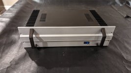
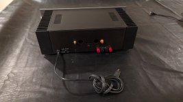
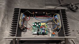
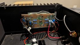
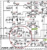
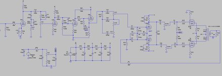
  4. 2 DIY Mono Block Amplifiers + 2 Active Subwoofers
    • Each amplifier receives one analog audio channel.
    • Amplifies audio for output to speakers.
Unfortunately, this setup resulted in stereo audio only, which didn’t meet my expectations. It could have been improved by using something like FFMPEG (thanks to @phofman for suggesting this) on the Raspberry Pi to process Dolby-encrypted audio over SPDIF for surround sound. However, I didn’t have the skills or the motivation to dive into that. Getting Camilla DSP working on the Pi and getting it to process the TOSLINK input was already a tough challenge. Once set up, though, Camilla DSP proved to be a great piece of software. The TOSLINK input had a specific quirk, requiring a special power-on sequence to work, which wasn’t very user-friendly for my household.

I considered the Vanity PRO, which seemed like the best affordable high-quality solution, but for my use case I couldn't justify the cost.

Then, I discovered a post from @yulen (on DIY Audio) promoting his 5AES to HDMI Black Box, which caught my attention, 
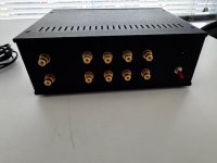
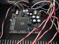
@mdsimon2 expressed an interest in the device as well. The product, a converter from HDMI to 5 AES, also includes optional DSP processing via Sigma Studio. It features 2x HDMI input and 1x HDMI outputs, with up to 4K @ 30Hz output. (Note: I have since edited this post to reflect the correct HDMI connections as I made a mistake in my original post)

While the product was intriguing, I had some concerns as it didn’t support Dolby decryption. However, the built-in DSP was a big plus for me. After several emails back and forth with Yulen (thanks for your patience!), I decided to try the product. Yulen assured me that it would work well with an Apple TV set to LPCM out, which was a perfect source for my needs—Spotify, Apple Music, Netflix, etc.

I made the purchase, it cost me $278 US or ~ £220GBP for the unit with the DSP module, this included tracked shipping to the UK, and within a week or so, the Black Box arrived—well-packaged and complete with the parts as discussed, along with the DSP board. I also ordered an Apple TV to pair with it.

To connect the Black Box to my DAC, I had to find a suitable DB25 to XLR cable. I then had to re-solder the connections to match the pinout of the Black Box (Yulen does sell premade cables if needed). This was my first time soldering a DB25 connector, so managing the soldering iron temperature and ensuring correct pinout was a bit tricky, but I got it done in a few hours.

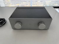
Without the DSP board, the Black Box is plug-and-play and works flawlessly. It automatically adjusts audio output from stereo to multichannel depending on the content being played (e.g., Apple Music defaults to stereo, while movies play in 5.1). I’ve even seen it handle all 8 channels of audio. Since everything remains in the digital realm, there is no loss in sound quality.

I’m currently running a 3.2 audio system. Since I haven’t set up the DSP yet, I’m only getting stereo sound and 3.1 channels for movies. Once the DSP is configured, I plan to add room correction and blend some of the rear surround channels into the front speakers. I also hope to split the LFE channel between the two subwoofers and add crossovers to the stereo signal to make full use of both subs.

Here’s the current setup, outlined in the flow chart below:

Flow Chart:
  1. Apple TV (Spotify and video source)
    ↓ (Audio and Video via HDMI)
  2. Black Box
    • Receives LPCM HDMI output from Apple TV.
    • Applies DSP (not yet implemented).
      ↓ (4 Audio Channels via AES/EBU) + (HDMI video signal to TV)
  3. Okto DAC8(8 Channel DAC)
    • Receives 4-channel audio via AES/EBU from Black Box.
    • Converts digital audio to analog.
      ↓ (Analog Audio Out)
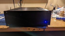
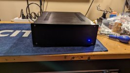
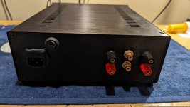
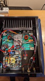
  4. 1 DIY Mono Block Amplifier + 1 DIY Stereo Amplifier + 2 Active Subwoofers
    • Each amplifier receives one analog audio channel.
    • Amplifies audio for output to speakers.
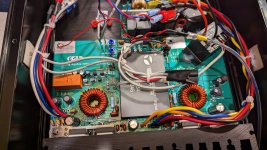
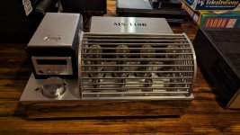
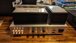
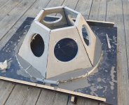
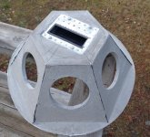
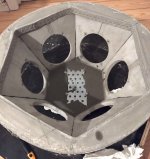
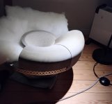
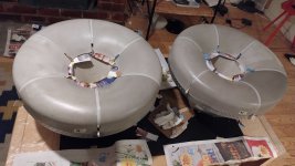
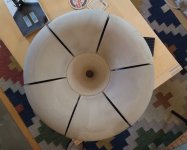
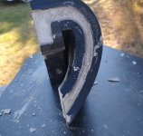
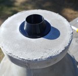
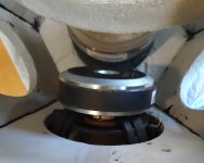
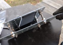
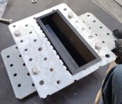
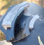
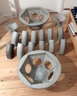
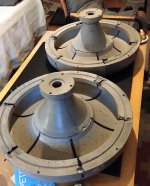
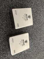
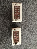
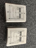
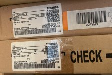
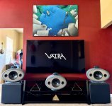
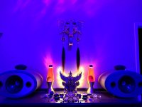
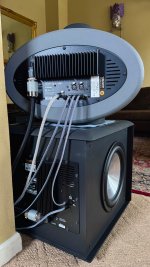
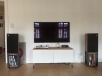
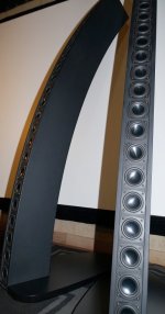
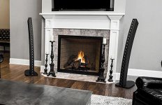
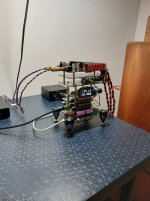
Images of it in my application:

IMG_0289.JPG


IMG_0291.JPG


IMG_0290.JPG


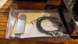
I ordered the required DB25 cable from here:
DB25 Cable

Additionally, I’ve ordered a generic UART USBi module and DB9 connector to communicate with the DSP board.

I support small manufacturers and appreciate the creativity and support from the DIY community, so I highly recommend checking out Yulen’s Black Box if you’re looking for a similar solution. Yulen also makes and sells other innovative products, which you can find on his blog (use a browser translator) and on his TikTok page, @SoundProAudio8.

He also has some upgrades for the black box in the pipeline, one is including HDMI ARC. Personally I would like to see 2x HDMI input with one being HDMI ARC, a boost in the frame rate at 4k to 60hz even though 30hz has proved fine so far and HDCP decryption. Overall I'm very happy with product though and even without any upgrades it's perfect, I'm looking forward to utilising the DSP in the near future. Note the unit already has 2x HDMI input and 1x HDMI output

Yulen is very patient and helpful but please be mindful of the language barrier.

Has anyone else used the Black Box and if so what's your application?
  • Like
Reactions: fb and yulen

OPA1656: High-Performance CMOS Audio Op Amp

Last week TI put a preliminary datasheet online for the OPA1656, a low noise, very low distortion op amp targeting audio applications and fabricated in a CMOS process.

http://www.ti.com/product/OPA1656

I just checked and the sample button for the prototype devices is now active:

http://www.ti.com/product/OPA1656/samplebuy

I started this project in 2017 with the designer of the OPA1622, and although I had a change in my role at TI before the device was released to market, I'm still very proud of what was accomplished. The goals of the project were fairly straightforward:

1. Start with the OPA1688 architecture which gives very good distortion performance, even with low-impedance loads. Beef up the output stage even more.

2. Push the input voltage noise down as much as possible. Ideally below the OPA1652 and OPA1678 levels, which are fabricated in the same process.

3. Don't let power supply current limitations get in the way of performance. OPA2134 and NE5532 both have power supply currents of about 4mA per channel, and have been widely adopted in the market (understatement). That seemed like a reasonable target for the supply current of the OPA1656 as well.

A quick snapshot of the OPA1656 performance specs:
  • 2.9nV/rtHz broadband voltage noise
  • 6 fa/rtHz broadband current noise
  • -131 dB THD+N at 1kHz, 600 ohm load, 3.5Vrms signal, 80-kHz measurement bandwidth
  • 53 MHz gain bandwidth product, 24V/us slew rate
  • >100mA output current
  • 4.0mA typical supply current, 4.5mA max

I'm looking forward to seeing what people think of the device, and hopefully it finds its way into a few projects on here!

Christmas comes a bit early this year! The single channel version of the OPA1656, called the OPA1655, released yesterday and the product page is now live on ti.com: https://www.ti.com/product/OPA1655

It doesn't look like units have been stocked yet for ordering, but they should be in-stock soon.

SM capacitor identification

Hi there,

I'm confused with Surface Mount electrolytic capacitors identification : are those 33µF/10V or 68µF/10V ? Please note I've been unable to measure any of them as they are all dead, their electrolyte leaked all over the PCB, causing a lot of damage.

Thanks !

Attachments

  • 1712560557982.jpg
    1712560557982.jpg
    759.3 KB · Views: 117
  • IMG_20240408_092941.jpg
    IMG_20240408_092941.jpg
    710.8 KB · Views: 113

What is the magic behind DHT tubes? Seriously...

Over the years Ive built many indirectly and directly heated amplifiers, and always if some dht was in the system, it sounded better in a way I cant quite explain. A lot of people build amps with them, they even started to be made again for new amplifiers etc. From the builders standpoint it has only disadvantages - you need separate filament supply for each tube, well filtered, current regulated in the best case, everything that happens on the cathode, every small hum or noise gets amplified. They are more microphonic than indirectly heated tubes. Now I have DAC output stage with the 45 tube used as a preamp tube. (if anyone wants more details, its choke loaded with output capacitors). And the same thing happened.
Like I said I can not even properly describe the sound. It never is boring every track is interesting, I actually enjoy music now. I stopped thinking about how to better the schematic, I just dont know what to play next. The sound is big, like even at lower listening values. Like it comes from nothing in the air. The voices and treble are heavenly. Music is now actually touching me emotionally way more than before. Like the simplest description that Im always saying is magical emotional sound. That just is not quite there with other tubes.

My big question is WHY, what electrical factors are different than from indirectly heated amplifiers? I really want to find out why this happens. I wondered the same thing in electrolytic vs foil caps in the power supply, but the explanation here was quite simple, being way lower losses in the dielectric, vibration not being a problem cause the foil caps are sinked in oil. The tangens delta difference between electrolytic and foil cap is like 0.3 vs 0.001. Plus the foil caps are way better at filtering higher frequency noise etc. But with DHTs I still dont know. Why nobody measured this?
Its the exceptional linearity (the curves are perfectly spaced and also as flat as a ruler).
Or its some microphonic feedback from the speaker vibrations getting to input tubes?
Or its the special care that you must take while building a DHT amp compared to indirectly heated amp?
Or its a different cause? I still dont know, does anybody has any ideas?

JBL 2384, Klipsch K402 or similar horns in Australia?

I want substantial horns for a home cinema speaker project, from JBL 2384 size as a minimum up to Klipsch K402 size. I won't buy from the US while they slap us with trade war tariffs, so do any Aussies either have, or know of any for sale already in the country? Or can recommend a local equivalent? Or even have a horn to loan that I can pull a mould from? (I expect it's too much to hope to find a ready-made mould)
If not then I may do a mould from scratch perhaps modeled in ATH software.
I would probably try a foam male mould, simple wet layup carbon fibre/Kevlar (well, not actually Kevlar,😉 probably a tariff free Chinese equivalent)
Would there be any interest in such a project? It's practically a patriotic duty🇦🇺😃

David

soundcard SW

I'm doing some playing around with active filter designs, and I'd like to get swept filter responses, showing the frequency response of the filters. I'm used to using a vector network analyzer for looking at RF filters, and I'd like to do the same at audio frequencies.

I've got a Focusrite Scarlet 2i2 3rd gen that should be able to do this, but I'm having trouble figuring out what software to use. I've spent some time poking at REW, and it doesn't look like it supports measurements like that. Are there other packages that will do that?

Help needed on Regulated power supply on Class A 6L6 amp

1000021842.png

I would like some input on this.
I am repairing a build of this amp where it is humming badly as the regulator transistor is blown. The particular device is hard to obtain so I tried something similar npn of 120v rating and it worked for a while but then blew as well, I imagine due to over voltage as the B+ is 350v in operation and about 400v at switch on.
The build had worked ok for six months or so but I wonder if the design is a bit vulnerable and could be improved.

Are there any similar amp designs I should consider for inspiration on improving this?

Many thanks

LP storage stand build

I've got a couple crates just sitting on the floor that I'm already outgrowing. So I needed something with a bit more capacity, and getting the vinyl up off the floor would be nice too...

I used the design here as inspiration. I don't anticipate needing that much capacity anytime soon, and I didn't want something that bulky sticking out into the room. Stacking single rows left-right simplified the design, omitting the center divider.

iW0fUEJ.png


Lumber was sourced from Menards. I can give more details if needed.

The width of the lumber I used for the side panels and bottoms allowed for a small ledge out front to display the "on deck" sleeves. I ended up routing out a flute along the top edge to create a lip that keeps the sleeve from sliding onto the floor.

image000000111222222s.png


I decided to give the side panels some shape. I made a template/profile board and used a flushing bit on the router to transfer the shape to either side.

image0000001112s.png


Simple dowel pin and pocket screw construction.

image000000s.png


image000003s.png


To prevent the bottom panels from sagging from the vinyl weight, and stiffen up the structure: I added some screws from underneath the bottom panels up into the front and back boards (not shown). It just wasn't needed for mockup purposes so I drilled the holes later.
  • Like
Reactions: planet IX

  • Locked
An article that urges the continuing significance of the string-quartet form


The Synopsis:

"My thesis is that music written for the ensemble of two violins, one viola, and one cello constitutes the musical art form that most nearly approaches perfection, both in its past achievements and its present possibilities. The greatest minds and most perceptive dispositions find in the literature and performance of string-quartet music an endlessly self-renewing source of wonder and delight. The string quartet is a most felicitous meeting of potential and realization."

There are several YouTube embeds, and a link to a Qobuz playlist.

  • Locked
Philharmonic Audio BMR Monitor: "The Loudspeaker Bargain of the Century—At least so far!"

BMR Monitors JM Revs.jpg

The pull quote above is the Subtitle of my Tracking Angle Review of the Philharmonic Audio BMR Monitor. BTW, the ArgentPur GaN-FET monobloc amps are AMAZING. Perhaps they are even "The Poor Man's darTZeel." That is, if Poor Men can afford $5,900/pr. SOTA power amps!!!

John Atkinson's measurements and Robert Schryer's review in Stereophile are required reading.

I have built more than a dozen loudspeakers of my own design (with help from outside experts!), and I can't grok (dating myself to the 1970s) how Philharmonic Audio can sell these for $2000/pair.

A cheap omni (aperiodic/weight on magnet)

I noticed that Amazon UK had some In Phase Car Audio XTC17.2 woven glass fibre coned drivers for £ 21.11p, so I decided to order them and make some omnidirectional speakers with them
IMG_20210818_104734.jpg
The driver is mounted on a small chamber that is connected to another, larger chamber by an aperiodic vent. My initial plan was to support the top chamber on coil springs with a foam seal, however the cast iron weights that became available ( the scrap bin at work ) are to heavy, and the temporary foam spacers that I used for initial testing work quite well

Cheap ADSP21489 + 4in / 6out PCM1798 board

Stumbled upon this interesting board on aliexpress, comparing the prices with other ADSP21489 sharc boards this is peanuts, and already with 2 ADC and 3 PCM1798 DAC boards for a 4in/6out system. Anyone have this?

Lusya ADSP21489 development board ADC PCM1804 Input board+DAC PCM1798 output board 4 in 6 out processor B4 007-in Replacement Parts & Accessories from Consumer Electronics on Aliexpress.com | Alibaba Group
  • Like
Reactions: YashN

floating ground Power regulator

I have a 5v regulator with a 2 wave rectifier.
The secondaries powering it are from 12.6vac heater secondaries. (tube amp)
The heaters have been elevated with DC so now I am trying to connect the reg board.
I have been told that I should float the ground of the regulator and relays but not sure how that is done.
Do I ground the the relays to the ground on the regulator board and nothing ground to the chassis?
Do I make the ground reference the junction point of the two 100ohm resistors from the heaters where they connect to the DC?

Looking for feedback on my DML instrument amp

Hi,

Inspired by the Voix du Luthier, I want to build my own instrument amplifier using audio exciters and a wood panel and I'm looking for guidance. I plan on using two 40w Dayton Audio exciters. I want to build the preamp myself and will likely use a class D power amp module. I'll be playing electric and acoustic guitar, synths, drum machines, possibly bass through the amp. Ideally it will be loud enough to play with a considerate drummer (say as loud as a princeton reverb)

I imagine the signal flow will look like this:
Input buffer -> Preamp -> resonant sweepable HPF and LPF -> Power amp module

The input buffer is there to accommodate hi-z and line level instruments. The preamp is for initial tone shaping. The two filters are important because they can be dialed in to approximate the frequency response of a guitar speaker or used for further creative tone shaping. This then flows into the power amp module

A few questions:
  1. Does a preamp differ from a tone stack? Can I build a 3-band fender tone stack and consider it my complete pre amp stage or is there more to it than that?
  2. Any recommendations for a solid state preamp stage for this project?
  3. Does the order of my HPF and LPF filters matter?
  4. I'm considering the ICEpower 50ASX2SE as my power amp, is this overkill for my project? It's expensive but I am most concerned with reliability. Any other suitable and more affordable replacements?

Any thing else I should take into consideration? Thanks for any help you can offer!

Is Creative Sound Blaster Z SE sound card good for PC/Digital crossover?

Hi,
I was searching for a good quality sound card with SPDIF input so that I can source audio from my TV (with SPDIF out) and provide 6 discrete good quality DACs for an active 3 way stereo speaker project. I am expecting quality than minidsp (ADAU1701 based ones).

Is this sound card Creative Sound Blaster Z SE good enough and a step above minidsp?

Thanks and Regards,
WonderfulAudio

Hi, Björn from Germany here…

Hi, my name is Björn, living in Germany.

I am looking for interesting discussions about audio/hifi equipment and sound improvements that I can use in my home.

I just upgraded my audio system to a WiiM Ultra Streamer connected via USB to a S.M.SL. PO100pro, to a Fosi Audio ZD3 DAC in Bypass Mode. I also have 2 Fosi Audio V3 mono amplifiers that drive a pair of Wharfedale Linton 85. My Turntable is a Thorens TD 203 with a BENZ MC silver cartridge. My phono pre amp is a Project Tube Box S2.

Attachments

  • IMG_7679.jpeg
    IMG_7679.jpeg
    443.5 KB · Views: 33

CBT wrapped around a Unity Horn

The fundamental issue with CBT arrays, and arrays in general, is that the high frequencies aren't well behaved. In the attached measurement of the Parts Express CBT24, you can things work great... up until about 2500Hz.

A thought I had, is that you might be able to wrap a CBT array around a Unity Horn. The Unity horn would have to be very very small; basically small enough to blend with the CBT array.

But this might be a way to get "the best of both worlds:"

1) Based on years of experimentation, I've found that speakers with wide horizontal directivity and narrow vertical directivity are ideal

2) But if you want to achieve that goal with a conventional Unity Horn, you end up with a mouth that's about the size of a door, like a Danley Jericho

Attachments

  • image (1).jpg
    image (1).jpg
    61.3 KB · Views: 331
  • 817dayton.promo_.jpg
    817dayton.promo_.jpg
    40.5 KB · Views: 325
  • image.jpg
    image.jpg
    82.5 KB · Views: 330

Sansui AU-D9 – Power transistors not amplifying after restoration

Hi everyone,


I'm working on a Sansui AU-D9 that had several issues, most of which I've resolved:


  • Replaced leaky capacitors
  • Removed the infamous "black flags"
  • Replaced the burnt output transistors
  • Replaced the drivers
  • Also replaced the distortion correction stage transistors

Here's what I’ve already checked:


  • Verified all flame resistance
  • Checked voltages across preamp, differential stage, and power stage
  • Found inconsistent voltages on two transistors (I can provide details)
  • The protection relay engages normally
  • All solder joints and PCB traces appear fine

The current issue is that the output transistors do not amplify.


Using an oscilloscope, I can confirm that the signal reaches the base of the output transistors, but it does not get amplified. At the output, I can only see the signal from the distortion correction stage, as if the power transistors are not conducting at all.


Bias is set according to the service manual, and the power supply voltages are correct.


Has anyone experienced a similar issue with this model? Or any suggestions on what to check next?
I'm happy to share measurements, circuit photos, or relevant parts of the schematic if that helps.


Thanks in advance for any help!

Attachments

  • MISURE STADIO DIFFERENZIALE.JPG
    MISURE STADIO DIFFERENZIALE.JPG
    222 KB · Views: 268

Massive preamp humm

I have a new build.

Schematic attached EL34, 12AX7 (preamp), 12AT7 (inverter)

There is a massive hum that changes pitch and loudness with the tone stack.

Trebble off, there is no hum, defiantly in signal path

With both preamp tubes out there is no hum.

With the 2nd tube in there is a little bit but not much at all.

When I put in the first tube the hum is there, and it is huge.

Master is up all the way, gain is off. ( first stage not the issue)

This has to be between the 2nd and 3rd stage.

My thinking is bad component or ground loop issue. Everything is new.

Currently R40 and D4 have been removed.
C22, C23, C13 are not installed yet

There is a grounding buss bar for the preamp section, the ground icons are where they connect to the buss, and I have noted how I have them grouped before connecting to the buss.


I have resoldered everything.

Not sure if this matters but C18 makes noise through speaker when tapped.

I changed that component, no change.

Amp does play

Swapped preamp tubes around but no effect.

Attachments

  • new build.JPG
    new build.JPG
    103 KB · Views: 166

Alex from Belgium

Hi everyone,

My name is Alex and I currently reside in Belgium. Started doing electronics projects while I was a teenager in Greece and when I have some spare time I like to play around primarily with audio projects, repair electronics.

I have currently 2 amps that I fully completed and are functional on my workbench:
  • A dual lm3886 built around 2012 (still need to add speaker protection though... I will eventually kill my speakers 🙂 )
  • A K502 kit with a quad of 11BM8 tubes (triode + pentode) that I built buil back in 2008 while I was in Canada

Gabster Td1 Dac with Ian Canada stack

Hey everyone, I just finished my first diy project which consisted of the Gabster Td1 V3.4 dac and Ian Canada's boards. Since I only needed it for usb and optical use a raspberry pi was not included in the build. Building the Td1 was fun and a little challenging; I would strongly urge any new builder to use fine low melting point solder, a small tipped soldering iron and flux on everything being soldered. The key for first timers is to follow Gabster's videos on his site when assembling. As for connecting Ian Canada's component boards it is critical to look up each board on his site and read the instruction manual for each product there. My interest in this project started when I stumbled on a Gabster video on YouTube. I thought Gaby was sincere in presenting his dac. As it turns out all of his claims about Gabster Td1 are true; it produces a huge sound (soundstage) with remarkable imaging that is almost addicting. I find myself listening music now way into the night. I use the Gabster dac in conjunction with my NSMT model 100 speakers which are known for their accurate sound and superb imaging.

Attachments

  • 20250417_172119.jpg
    20250417_172119.jpg
    511.7 KB · Views: 56

hello from a small studio in Germany

HI!

my name is Vincent and I own and run a studio/record label in a small village in Germany called binary pleasures.
I was interested in sounds and textures from a very young age and also love repairing and modifying electronics and equipment I use to work on music.
Now I would love to slowly step into the DIY speaker game but I am very overwhelmed by all the information both in the physical (acoustical) and electronic domain.
  • Like
Reactions: Drbulj

project: music visualizer (8x8 LED with time of flight sensor)

I am working on a little project to help me see what I am listening to in a fun way. The project uses a teensy 4.0 with a spdif in from a topping dac. The details of how I get spdif from the topping to both the teensy and hypex plate amps is a WIP. One route uses the WM8805 SPDIF chip and the other isolates the spdif to split it. The galvanic isolation is the first thing for me to try.

My user interface is pretty solid so far. I just need to link my two halves of the project together: the UI and Visualizer.

Here is an early UI test:
Login to view embedded media
The VL53L8CX TOF sensor can use a 8x8 grid at 15hz or 4x4 at 60hz. The video is showing the 15hz version. The current UI just uses 4x4 because the responsiveness is preferred. One just needs to select 3/4 of the blocks that make a corner to activate.

The visualizer currently has these modes:

COLOR_A_HEIGHT, // Height-based rainbow (Default)
COLOR_B_GROUP, // Band group color
COLOR_C_RED_SHADE, // Band red shade
COLOR_D_LEVEL_COLOR,// Column color by level (Bar Graph style / 16-band BG Fill)
COLOR_E_PIXEL_LEVEL,// Pixel color by position/level- each pixel cycles through a series of colors as the level increase
COLOR_F_DELTA_COLOR // ** NEW: Bar color by rate of change ** the time between level changes generates different color bars along with showing the active level

I plan on adding a few more. Maybe for L/R levels with the proper timing and the ability to change the calibrated level.

All of the colors work on a 8X8 full display or 4X8 with two rows. So a 8 band or 16 band visualizer.

Here's a summary of the frequencies used by the 8-band and 16-band FFT configurations, assuming a 44.1 kHz sample rate:

### 8-Band Frequencies:
Band 0: 0 Hz - 86 Hz (bins 1-2)
Band 1: 86 Hz - 129 Hz (bins 2-3)
Band 2: 129 Hz - 258 Hz (bins 3-6)
Band 3: 258 Hz - 516 Hz (bins 6-12)
Band 4: 516 Hz - 1032 Hz (bins 12-24)
Band 5: 1032 Hz - 6027 Hz (bins 24-140)
Band 6: 6027 Hz - 10036 Hz (bins 140-233)
Band 7: 10036 Hz - 22050 Hz (bins 233-512)


### 16-Band Frequencies:
Band 0: 0 Hz - 129 Hz (bins 1-3)
Band 1: 129 Hz - 172 Hz (bins 3-4)
Band 2: 172 Hz - 215 Hz (bins 4-5)
Band 3: 215 Hz - 301 Hz (bins 5-7)
Band 4: 301 Hz - 430 Hz (bins 7-10)
Band 5: 430 Hz - 602 Hz (bins 10-14)
Band 6: 602 Hz - 860 Hz (bins 14-20)
Band 7: 860 Hz - 1204 Hz (bins 20-28)
Band 8: 1204 Hz - 1721 Hz (bins 28-40)
Band 9: 1721 Hz - 2409 Hz (bins 40-56)
Band 10: 2409 Hz - 3442 Hz (bins 56-80)
Band 11: 3442 Hz - 4819 Hz (bins 80-112)
Band 12: 4819 Hz - 6885 Hz (bins 112-160)
Band 13: 6885 Hz - 9638 Hz (bins 160-224)
Band 14: 9638 Hz - 13770 Hz (bins 224-320)
Band 15: 13770 Hz - 22050 Hz (bins 320-512)

The short of it is that I get 512 bins in 43hz jumps.

Next up is to merge my code up and add more to the UI.

Amplifier Fire Safety and 3D filament

I have several Ideas for custom designed 3D printed brackets to mount boards in power amp and preamp designs.
This is especially nice for PS boards mounted above transformers is my dual mono and quad mono power amps - 4u and 5u empty space at the top can be utilized

Bambu lab has a flame retardant filament.

Any thoughts are welcome, thank you!

Attachments

  • Screenshot 2025-04-23 091218.png
    Screenshot 2025-04-23 091218.png
    707.3 KB · Views: 60

JL Audio HD750/1 flashing green light

Hello I have a JL AUDIO HD 750 that I'm trying to repair Maybe you could assist? Do you have a schematic you could send me ? The green light was flashing. I found 2 bad rectifiers and replaced them. The light was solid green and I got audio for a short time. There was some popping distortion...
It intermittently plays audio with a solid green light then switches to no audio with a flashing green light.

The caps and resistors and fets are testing good

SEAS MR18 3-way

http://www.diyaudio.com/forums/mult...coaxial-midrange-crossover-2.html#post5415661

So, now I have a pair of MR18 in my hands! My plan is to make a semiactive 3-way using it and SB29NRX woofers, floorstanding sealed box and minidsp PowerICE-125 amplifier-dsp boards.

Here are my first measurements of MR18 in a 7 liter closed box, baffle 19x28cm. We can see from nearfield measurements, that the peak at 5kHz is NOT exactly cone resonance, but more like a cavity resonance based on geometry. Look how nearfield off-axis measurement changes in normalized graph!


Looks like the tweeter shows directivity only in low treble and is exceptionally non-directive up to 10kHz. Crossing around 2,5 - 3,5kHz should be ok. Peak attenuation at 5kHz is perhaps not needed at all. Lower xo around 400Hz LR2 should be easy too.

Here some Edge simulations and a 3d sketch of the box. Top part of the baffle will be tilted and I will add diamond cuts to edges following the style of Avalon speakers. Box material will be MDF with birch veneer, tinted and waxed. These speakers will be a joint project with my older son.

Attachments

  • MR18 3way sketch.png
    MR18 3way sketch.png
    8.2 KB · Views: 2,354
  • MR18 3way woofer edge.jpg
    MR18 3way woofer edge.jpg
    239.3 KB · Views: 2,368
  • MR18 3way mid edge.jpg
    MR18 3way mid edge.jpg
    245.6 KB · Views: 2,316

Caps to attenuate bass

Hi Thanks for reading I have a pair of 2-way b&w dm110 speakers, and a m&k active subwoofer

The amp I am using with the b&w is a topping pa5 II

I want to create a 2.1 system and make the b&w speakers reproduce everything over 200hz, and the subwoofer reproduce everything under 200hz

I’m thinking of removing the crossover from the b&w, and replacing it with a 100uf capacitor to act as a high pass filter. I’ll probably have to play around with the value of the 100uf cap to make it integrate well with the subwoofer

Q: Are big 100uf caps safe to use with amps on a long term basis, and would there be any resonance problems you can think of

Building stands for a pair of Monitor Audio r352 speakers

Hello,

I recently picked up a pair of Monitor Audio r352 speakers of eBay, but they didn't come with any stands. I like the look of the stands that came with these back in the day (see the attached photo), but I can't find any information about them online. I reached out to a couple of eBay sellers who were selling the speakers with stands, but their either didn't reply, or couldn't help. I even reached out to Monitor Audio, who after a while got back to me to say they also had no information in the archive, nor did they have a pair in storage.

monitor-audio-r352-brochure.png


It's a long shot I know, but I don't suppose anyone on here has a pair of the stands and could supply me with the relevant measurements...?

If not, can anyone recommend some rules of thumb, around the size and thickness of both the base plate and column? The base of the speaker cabinets have captive nuts, so I guess the top plate size if pretty much self explanatory. The only other thing I really need is some for some guidance over the angle the speaker sits at.

Any construction tips for stands? Is it simply a case of screwing the column to both plates and calling it done? Or is there a better way of joining everything to help dissipate, or mitigate, vibrations coming up from the floor?

Any help would be much appreciated.

ICEpower 1000A help to identify parts missing

Hi All

Please help to identify the parts marked in the Ice Power 1000a module picture they are adjacent to the input connector. I have 2 modules one the parts have unfortunately come off and got lost in transit and one module with the parts populated. Most of the components are marked and identifiable, somehow the parts that went missing are not marked.

Below is the module with the parts missing in blue
1000a Parts Missing.jpeg

Below is a picture of the module that is with all the components.

1000a with the parts.jpeg


Thanks.
Projects by fanatics, for fanatics
Get answers and advice for everyone wanting to learn the art of audio.
Join the Community
508,209
Members
7,908,086
Messages

Filter

Forum Statistics

Threads
407,166
Messages
7,908,086
Members
508,209
Latest member
geegorge