Tivoli Model One BT with bluetooth. All inputs are muted EXCEPT when using the Bluetooth input. Even the line aux input is muted which is on the same switch position as the bluetooth. On other switch positions, i.e. TUNER, can hear audio at very low level with ear up against the speaker, no audio from headphone jack either. Tuner is working because can see the Tuning LED light, and can see audio with a scope on the solder side of the 12 pin connector that goes to/from the volume/switch board. My guess is that the audio board has a solid state audio gate or switcher that won't release the mute when it needs to. Due to the audio board likely being multi-layer SMT, I am probably hosed!
I buy my dreaming(for 30 years) speakers DUNTECH Sovereign 2001 recently.
I had replaced original DA drivers with modern Scan-speak drivers .
Next step will be revising original passive crossover or jumping to active crossover???
Hoping that I can find the best answer here!
Thanks everyone!
IB's are already up and running since a couple of years.
Midbass enclosures will be sealed (not ready yet) around 40L net volume per woofer, 2 per side. Expected to be crossed 80 - 300 Hz.
Midrange enclosures will also be built sealed with a volume of about 15L per box. 1 driver per box. 2 per side. 300 - 2000 Hz.
TPL-150B with open back into sealed stuffed cavity modification from 2000Hz.
It will be a IBWWMTM...? 🙂
This will be an active 4-way system with Minidsp OpenDRC-DA8🙂confused🙂 and Crown XLS amps for the woofers and Firstwatt M2's for the mids and tweeters. Expecting 100dB+ sensitivity.
I'm a total noob when it comes to Minidsp so this will take some time to learn. Done some studies already and it does seem quite easy to get started anyway. Time will tell.
If somebody has a better suggestion than the OpenDRC-DA8 for X-over and DSP duty, please do tell. We have no secrets...
Hello everyone, I'm looking for someone who can take care of and have fun with a PCB from the wonderful project that Mark designed for us. I ordered five from JLCB, one is attached to the magnificent line stage that Wayne Colburn designed in 2018, which I use, another is in the same preamplifier of a friend of mine, and I'm using a third one for another project.
Two PCBs are available; I only ask for shipping cost reimbursement. I think it would be convenient only for those living in the EU (I'm in Italy).
One of my headphone cable models 'The Crystal Cranium v2.0' has a cable geometry consisting of 4 hand-braided (by me) strands of 4-core pre-braided (by supplier) cable.
Subsequently it has a pretty chunky overall outside diameter and for a cable needing a 4.4mm balanced source connection it requires a Pentaconn connector with sufficient internal diameter and rear aperture to accommodate the cable.
My regular Aliexpress supplier has disappeared without trace. It took obtaining sample connectors from about 30 different suppliers until I found him and the really decent connectors he was selling. Nobody else there or on alibaba, bang etc was selling these things, so I had to start the whole process again - sourcing a decent connector from a 'reliable' source.
I found a couple of suppliers recently with in-spec connectors. One has an 8mm OD aperture and the other a 7mm aperture. Both seem good quality, well-machined and smooth barrel threads, good quality barrel paint and both have decals. Both are also gold plated and not just painted and measure about the same for capacitance.
Slightly different designs but at least I have 2 viable candidates for wide-body Pentaconn connector supply.
However, I can't help feeling that aliexpress sellers are jumping on the 'posh packaging' trend and bumping up prices accordingly. There was a time when you could pick up a box of baggied connectors like these for not much money, but these days they come in fancy packaging in multiples of 2 or 4 with a hefty price-tag.
Any other MOT's noticing this trend?
Somewhat irritating when you try to keep your own prices consistent and stable. :/
It's almost a bit of a shame that I seal the connectors to the cable using glue heatshrink but it makes them very strong and prevents the terminations from oxidising.
Starting this May 2 the minimum processing customs fee for a package from China into the USA will be $25. That's on top of the new tariff being added. Processing fee goes to $50 in June. Gone will be the days of 5 100mm x 100mm PCBs from JLCPCB for well under $10 delivered to your door.
I have a Hafler HA15 in pristine condition. Unfortunately, it doesn't work. If you have the skills to fix it, I will gift it to you for free, you pay shipping. I have the circuit diagram from the manufacturer but they said they can't help. If you want this piece, let me know, but I would like an assurance that you actually have the chops to repair it.
I'm just thinking about improving my loudspeakers: Braun LS200. I'm curious if the drivers' positions on the speaker baffles were rearranged to follow D'Appolito's MTM layout. Is it absolutely considered an upgrade? I mean, is there any obvious improvement?
Here's a beautiful image of the LS200 from its brochure.
My idea for converting them to MTM style is shown below.
A thread on this topic could be an inspiration for newbees & interested folks
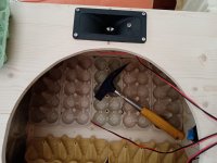
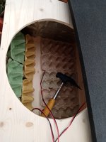
Here some ideas I realized:
glued in egg crates (the real ones) and using a thin sheet of damping. Thats for being localized more in the middle of the box where it is damping lower frequencies than only being positioned on the walls
reflex port in the corner of one wall as a cutout and port made of cardboard sheets glued in. Easy to realize bigger port diameters like this.
piezo tweeter on the side for indirect high frequency dispersion but it can be put on and off to taste
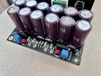
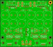
This is GB for APEX A-CLASS PSU that is designed to supply in parallel (SHUNT topology type) preamplifier and any audio circuit that needs low noise and low TIM.
Output voltage can be adjusted from +/-12VDC to +/-24VDC and max output current is set using R7 and R12 resistor. For heatsink you can use SK574-50-SA or you can use aluminium bracked that is 50mm in length, 8mm thick to cool down output shunt and ccs transistors.
This is improved design from APEX A-CLASS PSU that have improved low noise voltage reference (100uF capacitor at -IN), upgraded JFET-s that is very easy to but from mouser, and using low noise ZTX bjt for lowest noise of PSU. Input filter is RCLC and is used to suppress any noise from low frequency to high frequency. If you don't want to use L in this filter you can install two 4.7R 0.6W resistors.
PSRR is -150dB, output voltage noise is about 10-20nV/sqrt(Hz) and uses easly available TH parts! (For HLMP-6000 if you could not find one in mouser you can use standard 3mm RED LED and solder it under PCB as is in footprint).
Price for 1pcb is €6,00 plus shipping (shipping cost is from €15,00-€20,00 as these days shipping cost is high). Payment Paypal F&F only.
APEX A-CLASS PSU LIST:
nickname (number of pcb) - COUNTRY
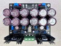
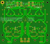
Here is pictures of PCB that is professionally routed using all audio technique that is very important in audio psu design.
And here is how it looks when assembled in 3D (Here for GB is only PCB).
I'm planning some new open baffle full-range concepts and just want to know which are the best drivers you've ever listened to.
I have a weak spot for vintage paper cones and would appreciate recommendations in this field but modern drivers are also fine.
Right now I listen to a 60s 12" Fane driver which I like a lot.. just asking myself if there are better (paper) ones.
(I know that the word "better" could be ambiguous. Of course there are modern full-range drivers that measure much better but I like the naturalness of paper cones)
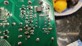
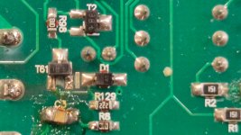
I picked up this dead subwoofer at the weekend mainly to harvest the drivers for a DIY speaker project. (They're pretty mighty things)!
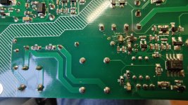
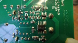
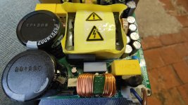
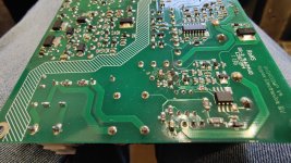
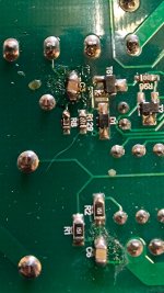
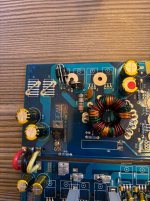
I hadn't realised the PV1D has a Hypex amplifier and I thought it would be good to try to make the thing work. Looking online seems that the OEM Hypex with the onboard SMPS are pretty problematic.
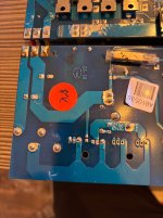
Once I'd got it off the heatsinks board I could see an area that looks like has had some intervention before. (C3 and C6). I measure 240v into these.
Also T6 looks suspect, or atleast it's soldering.
I haven't probed much beyond that area, other than various electrolytic caps, and they aren't charging. So the mains AC isn't getting far into the circuit, which I hope narrows a few things down.
Obviously we can't get a scheme for these but is there anyone with SMPS knowledge that might hazard a guess where this could have failed and possible replacement parts. Or where to do some meaningful probing;I'm struggling to see the identity of T6.
Thanks
I just cobbled together a sim for a UcD headphone amp. This is my first amp design from scratch.
This is a first step towards a 100W amp. I figured by ruling out most of the power stage, it'll be easier to get something working. My emphasis is simple and easy to build.
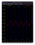
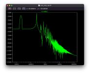
Briefly, it's built around the LT6274. One unit for the comparator and 3 as unity gain buffers acting as the power stage. Comparator output is clamped by zeners to limit output swing and not over drive the power stage.. The hysteresis is added in hopes of avoiding driving the comparator into deep saturation. There's no feadback compensation network, just a divider to set gain, and the output filter is heavily bypassed. In a rev. 2, I might revisit a proper comparator and the simplest way to manage differing supply and output voltages between that and the power stage.
I set out measuring propagation delay (285ns) doing all the math for lead/lag networks but in the end I couldn't get it to oscillate much above 150kHz, which is what lead me to rip out all the compensation and bypass the output filter. It switches around 250kHz but still has rise/fall times 200ns-300ns. It provides 5dB gain, clipping just past +/-0.8V input / +/-2V output, delivering ~50mW RMS into 18 ohms.
All in, 4 op amps, 12 passives on split 9V supplies (easy with batteries).
I'm excited to have gotten it working, but not happy about not understanding the lead/lag compensation.
Hi,
How to measure and test the output transformer of the tube amplifier with signal generator and oscilloscope. How should the connections be. Can you share any videos or documents.
Is it possible to use the BA-3 front-end as a pre-amp? I think I read it can, but can't find the reference.
Has anyone used it as pre-amp and do you have any impressions on the sound? I'm currently using a BOZ-J and would like a bit more drive for a bi-amp setup running the L'amp CCS and a F5.
Thanks,
Vince
Note:
If using Fairchild mosfets, use 1K variable resistors for P1 and P2.
Hello all!
I have this amplifier…the rectifier diodes are replaced,i dont know why,but i see the FED16BT…is this the original rectifire diode?
D5/D6 are same FED16?
I own an Involve Audio Surround Master v3 that does SQ/QS decoding, as well as a wonderful job on some stereo content of upconverting to 4.0 or 5.1. The only trouble is that the SMv3 only has analog output, and my AVR only has digital inputs (HDMI, S/PDIF).
Somebody mentioned on the QQ forums in early March that HiFiBerry had started selling an 8-channel A to D hat (“ADC8X”) that might do the trick. So I took the plunge, bought an RPI5 kit, plus the DAC8X and ADC8X hats from HiFiBerry. The ADC8X requires the DAC8X, but as with their other hats the price is not bad.
Success! I loaded up the headless version of Raspbian, added the ADC8X overlay to the configuration file, and found both the ADC8X audio input and HDMI-1 audio output ALSA cards with “arecord -l” and “aplay -l” respectively. After connecting the pieces together (SMv3 to ADC8X, RPI5 to my AVR via HDMI-1) I tried the simplest approach:
This (192k/24) uses up about 7% of the cpu (according to “top”), with 48k/16 using about 2%. I could have used 6-channel mode (“-c 6”) but with 8-channels I can wire the two rear channels Lr and Rr to the 7th and 8th inputs, and my AVR will then play those channels on my rear speakers instead of Ls and Rs (as the quadrophonic gods intended!). I haven’t had trouble with underruns or overruns, but I may just be lucky with well-matched ADC and HDMI clocks.
ALSA also provides a simpler command, “alsaloop”, for this purpose. I’ll probably modify the code to add some logic to prevent underruns and overruns. I decided to stick with the lowest level in Linux (ALSA) rather than go up the audio stack into PulseAudio or PipeWire (the KISS principle).
I also have an old Korg D888 8-channel analog recorder that is nicely replaced by just recording with Audacity from the ADC8X on the RPI5.
If anyone is looking for an inexpensive 8-channel ADC, or for an analog to HDMI converter, this seems to fit the bill. The DAC8X makes a nice 8-channel sound card as well.
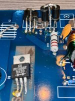
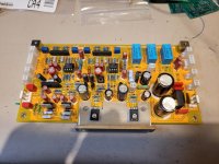
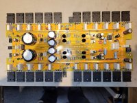
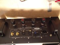
Hi. I'm starting this new thread about my Accuphase P-7100 amplifier clone. Most of the owrk is already done, and I just completed both amplifier module last week.
I tested and preset both amp modules today and everything is looking good. I pre-set the bias at 5mV on the final instead of the specs 20mv (20mv / 2x 0.47R = 21ma / Transistors
The front end and Meter/Softstart/Protection PCB are tested and working fine. The main +/-75V Power supply is already assembled on the chassis. It is made of a massive recycled Rotel potted power transformer, two large 51,000uF/100V Kemet power capacitor, as the original just one 35MB100A, 35A, 1kV rectifier bridge and a copper GND bus bar as the original.
I'm trying to emulate as far as possible the original, since I know the Accuphase sound and love it. I went throught the service manual and decoded the detailled BOM that list all the type of resistors and caps used where (film, carbon, MOX, carbon film, and as far as possible the same caps series and type).
The PCB, original clone of very good quality (2mm, gold plated) are from ebay. All the pcb were replica of the original and match the service manual schematic, except the Meter/Softstart/Protection PCB. The original processor amp control was replace with discrete circuit, and the usual uPC1237 protection IC, but there was no info on it, and no part values. I had to find the circuit and test my mods by myself. The input stage pcb is the same circuit but the parts ID are different from the original schematic, and some small differences are there as well. I documented the changes and wire the board accordingly. Chassis is a clone from Aliexpress.
The original amp section used 2SC5358/2SA1986 (230/15A), me I'm using the 2SC5200/2SA1943 (same 230/15A) that I bought years ago, and match them myself.
I used thermal spread aluminum bars to mount the power amp transistors, and to add rigidity to the clone heatsink made of two section. The output amp module is now solid as a brick. The amp pcb also inclded nice brass bus bar and input transistor pairs rubber caps, as the original.
Here some pictures of the PCB. There are some extra PCB such as the rectifier PCB and Softstart and Ground Lift PCB.
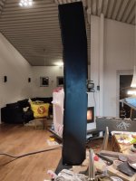
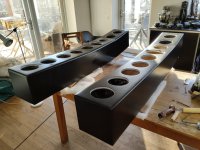
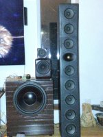
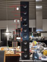
I have build a 2,5 way linesource with 8 Peerlees fls-0512 5,9 inch midwoofers per side, and using a Audax "gold" TW025A28 in a WG as tweeter.
Diffucult to measure with a speaker thats 152 cm in hight, and have drivers from bottom to the top.
The linesource will also be mounted on the wall, with tweeter at 3/4 up on the tv.
Measurements done with speaker 1 m obove the floor, faceing into biggest reflexfree area in my house.
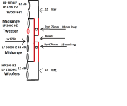
measurements on 2 lower woofers together from 1 m (connected 8+8 ohm)
Done measurements on 2 higher woofers together from 1 m(connected 8+8 ohm)
Done measurements on 2 lower midranges together from 1 m(connected 8+8 ohm)
and done measurements on 2 midranges over and under the tweeter "MTM" together from 1 m(connected 8+8 ohm)
and tweeter measurements from 1 m
The drivers are then paralellconnected in pairs to 16 ohm, and then in serie outside at the xover so 8 ohms load.
Problem is that measuremenrs still become 16 ohms, and when i put it in VitauXcad nothing becomes "right"
So making simulations doesen´t help mutch, and don´t look as my test measurment on hole speaker.
And room is 3,8 meter frontwall to backwall, speaker steals 24 cm and in total with my head and sofa tha maximal listeningsdistance is 3,2 meter.
Speaker play real good today crossed at 1,5K and ca 3K (with lots of xover work), but would like to be able to do correct simulations in VitauXcad.
One more problem is my health, so can´t carry around the ca 35 kg high "thing"
I have a damaged what I think is a Fishman Powerjack from a Martin Acoustic Guitar does any body have any info like a schematic there are two damaged component next to where the wiring holes are located
I have 2 subs. DIY BMS18" in sealed boxes.
places in front corners of room on the outside of the left and right speakers. (typical setup)
I have used various room correction software e.g. Dirac version 1, YPAO, Manual EQ etc
my issue is that, even though my subs are time aligned and level matched to each other and I verify with REW. when I measure the FR of one sub, then the other sub, and then combined, most of the frequencies sum greater when combined like they should.
but there is a specific frequency that doesn't. 40 to 50hz huge null.. this doesn't happen in the individual sub responses. once combined the magnitude at this frequency is lower than that of a single sub. As if they aren't aligned.. but they are. for most frequencies. Just not at 40 to 50Hz.
if I reverse the phase on one sub they sum beautifully at 40 to 50hz, only to ruin the rest of the frequencies as this is obviously incorrect.
How do I fix this? I have read that all pass filters work to change the phase but keep the magnitude the same. But others tell me its not a phase issue but a room issue?. have I not just confirmed that the phase is the issue? I just need to know why this is happening and the correct approach to fixing it.
Hi,
I was watching some videos from Audiophile Junkie on YT where he's covering the Montreal Show.
I saw this new speaker that looks like a G Clef that has the woofer / mid as a face to face isobaric design.
In their design It looks like each speaker is in a sealed 1/2 shell and there's a gap of about 2 or 3 inches. (Estimate from looking at the video and pictures)
see: https://www.stereohifi.nl/loudspeak...aker-t/stereowise-l-speaker-treble-clef-audio
I'm trying to understand the benefits of a face to face isobaric design.
In some other speakers, it looks like you have both speakers facing each other attached to the same baffle so there is no gap.
So here's the questions...
1) Benefits of isobaric in general?
2) Benefits of face to face isobaric.
2a) One side sealed, other side open? (A different speaker design...)
2b) Both sides sealed, but there's a gap between the two drivers.
3) The gap between the two speakers... advantages/disadvantages ?
3a) Is there any math concerning the width of the gap?
4) What other considerations?
I mean its an interesting design... I'm curious about the acoustics. Imagine taking a 6.5" purifi woofer (extended range.)
The data sheet says sealed bottom frequency is ~77Hz, Ported drops to ~44Hz. What could you expect from a face to face isobaric ?
Is there any good material on isobaric speaker design?
I know that Mon Acoustic has an isobaric speaker (face to rear)
I realize that doing this sort of design gets expensive really quickly and its more of a thought research project while I'm out walking my Husky.
Selling two new, unused Beyma 12xa30nd coaxial drivers for 600 Euro + shipping fees. The drivers were purchased for a project that was never realized. Since then, they have been stored in a cabinet. The speakers have always been stored upright to avoid cone sagging. I live in Vienna. Shipping is, of course, possible, and if you're interested, I can check the shipping costs.
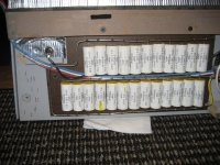
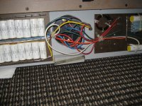
I have been lucky enough to score said amp for a really good price, but sold as defective because the transformer humms - you can hear it from at least 2m (7 feet). The seller, knowleadgeabli in tube amps said a new transformer is needed (also mentionet that all s150 he encountered hummed).
My first question would be regarding the humm - is there something i can do to improve the situation? Also might it have something to do with the voltage in the EU (currently 230 as opposed to 220 in the past).
Another question would be regardin the mod - moving the transformer further away from the left sided pcbs.
As i have more projects started, this will have to wait a bit, until i fill a mouser cart at least, for the ageing parts (caps, diodes and trimmers).
The sad (or is it funny?) part is i have no means of hooking it up at home, as i have no preamp or amp with jumpers to use as a pre.
Pictures will have to wait.
Speaking of KSA-100...... is anyone out there interested in persuing this amp as a project? I would definately want it to be the MK-2 version. All semi's are still available excepting the VN and VP series mosfets. These however could be easily subbed by modern IR units, perhaps using the IRF9610 and 610 devices.
This would require a new board design (Al Perhaps)? I would be willing to front the $$ to make up say 100 of them so they are available.
This seems like the next logical step in creating our own Krell Klones... then perhaps on to the KSA-80 or 160.
Let me know your ideas and opinions on this(constructive only please).
I started working on a Heathkit AP-1800 Preamplifier that lost the left channel. The included documentation of this preamp is very thorough, but many of the transistors have a proprietary Heathkit part number that I can't find information or datasheets on.
There many of these two BJT's used:
SM07275 (NPN) Heathkit Pt#417-283
SM62186 (PNP) Heathkit Pt#417-284
I pulled several and tested with a Peak DCA75 analyzer.
BC547B/557B could be a possibility, but with so little info known about the originals, I'm not confident enough about this choice.
The PNP's have the dreaded black legs up to the transistor base with webbing connecting the three legs.
Any information would about substitute BJT's be greatly appreciated.
I'm into home audio and all things nerdy and tech. I run a Classe preamp and amp, Magnepan front and surrounds, and 2x SVS PC-4000 subs.
I'm into cool gear and excited to see what people have got!
I'd like to tinker with some weird bluetooth modules and other components and have previously built a neat IR blaster to interface with my Classe CAV-75 since it doesn't have a remote 12v signal and can only take a pulsed turn on signal.
Hello there from Tasmania, Australia. I work on mostly amps and tape decks but sometimes CD players too (more now than before). I'm a hobbyist and enjoy late night DIY electronics.
I have been thinking about the gain structure of pre and power for a home theater amp or stereo amp with pre section being solidstate and tube
consider a tube pre with gain of 20 and power amplifier with gain of 20 log 33 or 30.37 db so how much this ratio needs to be where in tube pre I cannot change the gain but can change the gain of the power amp. I do understand the total gain ratio but what is the usual case i feel even amplifier with 26db is quite high if we have a tube pre with 20 gain
Another scenario with solid state pre with 6db gain and power amp at 30db gain so what is to be taken into consideration
For HT application
For Stereo application
Now do commercial HT amps comes with pre gain stage inbult? as the AV processor or receivers dont have a proper standard some give 1Vrms out and some are capable 3.5Vrms out
Can anyone please provide few inputs on this
Sometimes I wake up in the morning and it’s just playing for one reason or another…in my head.
There could be a million reasons I suppose. I could have heard it anywhere.
Sometimes I know where I heard it…sometimes I can’t figure it out for the life of me.
Sometimes it’s a song I love…other times not.
This morning it was “I’m gonna sit right down and write myself a letter”.
I quickly realized a version of it was playing in the background from the Eiji Kitamura Hit Kit Party while I was tinkering away at my workbench on my Iron Pumpkin project yesterday afternoon.
Funny that it was instrumental and so kind of just snuck in there without me paying much attention.
It actually made me want to hear the song and so I went searching for one of my favorite renditions which is by Madeleine Peyroux in her Dreamland album.
I made a trade for a pair of preowned Quicksilver Mono amps on the weekend. One amp makes an odd noise a few seconds after it is turned on. It only lasts a second then goes away, so I'm not sure if it's something I should be concerned about. It's a mechanical "whumm" sound and isn't coming from speakers. Kind of sounds like a lightsaber from Star Wars, lol. I've attached a video so you can hear it. The noise happens 12 seconds in.
Any idea what might cause this noise? I think it's one of the transformers, but I'm not sure. Amp seems fine otherwise, but I'm worried it could lead to bigger problems down the road if not dealt with. I also emailed Quicksilver, but thought I'd ask here as well in case I don't hear back from them. The seller said I could return amps if I'm not happy, so I'd like to make a decision soon.
I thought I should post pictures of my first build.
Project was inspired by Cabasse and the curves employed in B&W 800 series, although on a much smaller budget. Had the idea to use bowls, Ikea had the wooden Blanda which seemed perfect. After scouring the net, found several others using these, although none using the 28cm versions. Design is an active 2 way design.
First completed photo (no tweeter), initially using Zero class T amps.
Current incarnation, using rotel 6 channel amp, channel for tweeter and mid, bridged for 15" sub, experimenting with solid oak sleeper stands and granite plinths.
Tweeters rather delicate positioning on top, seems to be fine without an enclosure, however I am experimenting with casting tapering tubes using champagne flutes.
The Sound: To my humble ears they sound rather good, haven't obtained a microphone to do testing. Definitely better than my Mission V63, which have an rrp of over £500. The 'no baffle' 15" add good low level sound reinforcement, as they don't go terrifically low or have very much bass
The tweeters are also Peerless metal domes, model unknown.
Currently crossed at 15" Sub 20-150Hz, Mid 50Hz-3Khz, tweeter 3Khz-20Khz
The sphere's come in at around 8L, (9.1L before cuts and driver displacement) One has eggfoam stuffing the other is naked will aquire some different materials for testing when I have a good mic.
They need another sand down, better integration with the stands and experiments with internal wadding, and the new tweeter housing, when time allows.
Hi, I accidentally bought a maintained contact switch and a soft start that is designed for a momentary contact switch. Is there any way to convert the soft start so that it works with a normal switch
Here’s a link to the soft start that I am using https://www.audiophonics.fr/fr/soft...et-protection-pour-amplificateur-p-10225.html
On the soft start there is a Texas Instruments NE555P which acts as the timer delay for the soft start but I’m assume it also gets the input from the switch.
When I read the data sheet for the ne555p it said you could use it in monostable or astable configurations. Is this what I need to look at to figure it out or can I just solder the switch into two points on the soft start to fix the issue?
I’m new to diy audio but am in the process of building my first amplifier, it also the first amplifier I’ve ever personally owned. I enjoy electronics and want to learn more about audio in general. I’m very passionate about music and would like to learn more about diy music making techniques in the future.
Hello, I recently bought an harman/kardon AVR 255/230 second hand. I set it up, everything worked fine until I was setting up my Fire TV Cube to be able to control it. It tried to send some command where it switched sources (not exactly sure what it was trying to do, maybe it also had something to do with muting the source?) and since then there is no audio.
I have tried:
using multiple sources (HDMI, digital audio, analong cinch; both back and front panel ones)
factory resetting it with holding OK button (Tho there is a reset button in the back near the RS323 port, which I don't know how works)
tested speakers - there is no short
Additional information:
video out works fine
there is no error message on the screen (both built in and hdmi out)
while playing the test tone (speaker level setup) there is noise coming through the speaker at max volume
noise coming through the phones port while trying to play music at max volume
at first after the speakers stopped playing the phones port continued to work, however i disassembled it to look for burnt components / bad soldering points / overall loose things (found none)
I tried testing resistors labeled 0.27ohmKx2 5W KW0807 but was getting weird readings - all were 0.0-0.1ohm across them so I figure I was measuring them wrong
I tried testing transistors behind them (diode mode on multimeter) got readings: left to middle pin is 0.6v, left to right pin is 0.6v, middle to right pin is 1.2v - this is on the ones I could access (only two of them)
Anyone have experience with something like this? Any advice on what I should try / test? I have no problem disassembling it and sending photos of things / testing individual components.
In advance thank you for any help.
hi there,
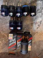
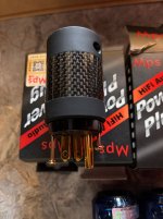
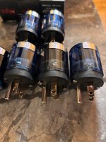
I want to sell a lot of US/Japan power plugs, the lot includes the following:
3x MPS HADES - new, unpacked, but unused, never installed on any cable.
2x Oyaide - removed from oyaide Black Mamba V1 cable and Oyaide power distributor. These seems to be unplated phosphor bronze. Used
5x Oyaide beryllium copper silver and rhodium plated. ---> these are truly special and you cannot buy them on the market. Shells are taken from other original Oyaide plugs (c037 and P004). These plugs (blades to me more precise) are made exclusively for AcroIink in Japan and were removed from US/JAPAN standard high end acrolink power cable.
Contacts: beryllium copper
Coating: polished silver + rhodium
these five plugs (blades) are IMO one of the best money can buy. I compared them to Oyaide P037, P004 . I dount count Furutech as generally speaking I am not NCF fan.
I have no usage for US/JAPAN plugs here in EU, therefore want to sell these.
400 EUR / 440 USD via bank transfer. economy worldwide shipping included. This is my best price already. If youre into DIY'ing power cables - try these five oyaide plugs and you wont be dissapointed.
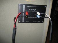
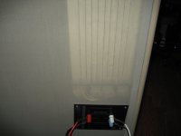
One Ohm model. One speaker OK, while other has bass ribbon panel damaged & removed...a multimeter fell onto the foil as I was completing the "Silicone fix" years ago (still have not gotten over it)...
Both tweeters are there and functional, albeit both ribbons appear stretched.
I do have a pair of replacement Bass Foils (actually the entire Kit) from Patrick in Germany that I bought many years ago (not cheap at $1300).
Covers are painted Matte Black (used to be that ugly Beige)
Been sitting in my back room past few years....wife would like them gone.
Pics taken years ago attached...
Pick up in West Sub of Chicago, no shipping. I also cannot assist on the repair.
A less-than-two-minutes, eight years old news video of a man who paid for his own utility transformer and pole to get "pure electricity." I vaguely recall reading about such a person years ago - perhaps it was this man, or maybe there's several who have done this: Login to view embedded media
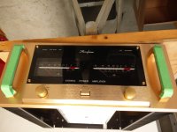
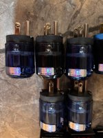
Hello, I have two Xa60 mono blocks that I love and that I use for my Tannoy Kensington GR with a Mcintosh pre-amp. I bought them used some time ago from a professional. I wonder what the needle on the front is for, in fact when I turn on the device, the needle blocks towards the right, I don't know if this is normal, because I see an intermediate position at noon but the needle never went there. I would like to point out that I don't listen at very high volume. Thanks for help
Can't understand why to use differrent gains for negative and positive rails ? What is purpose ?
This is a piece of schematic from one factory made device. "Balanced" in quotes because of input.
i am thinking about the recycling of a very old pair of Monitor Audio Monitor One speakers
I have some very different chassis already available for the exchange of the old chassis
I have a mini DSP 2 X 4 HD box and still struggling with the power amps
best thing would be to flip to something like Hypex FA122 but for the first development approach i will probably use the power amp section of an old Yamaha AV receiver
next post with some options about the new chassis
I have the CLIO pocket measurement system and unfortunately a big lack of ability to use Vituix CAD but a dozen of years of experience with Visaton Boxsim
I will use Ale's Moglia aka Bartola Hybrid mu-follower as anode load.
I will need to mod the Vout LT PSU for filaments, I have a couple of Lundahls Filament Current Choke LL1694 that can be configured as serial or parallel also common mode choke and choke input. Could be configured as choke input CMC?
Anyone suggests any mods ? I have replaced the captive leads.
I was thinking of first looking at the capas in the analogue section. My main problem is how you get the analogue board out . I figure you go in from underneath and remove a torx screw holding the board in place. Is there much more dismantling to be done , or is there a special way of removing the card ?
Heat Sink thermal resistance: 6.2C/W - 11.4C/W, depending on the length of the heatsink used (ref. attached pdf)
Board Size: 103,5mm x 91,5mm
Added:
Optional half rectification diodes D98 & D99 have their own place on the PCB. Remember, they are only used for half rectification, when using a transformer with only ONE secondary. They are marked with a *
Added an optional resistor (R23, R24) in parallel to every one of the Variable resistors (VR1, VR2), in case you want to replace the Variable resistors by a fixed one.
2x Outputs, CON1 and CON2. CON1 supports many readily available connectors. CON2 supports Faston terminals OR Europlug
Added R100, a way to connect the ground plane to chassis via the top right mounting hole. You can short it or use a resistor 3-10ohm
Have fun!
Alexander
Disclaimer
This thread is made by a fan, it is not affiliated in any way to Mark Johnson's work and the original VRDN thread.
This layout is a DIY project done by me, provided "as is", with no official guarantee it will work.
Hello Everyone, Thanks for accepting me. I'm from the US and retired in Chile. I've been interested in Hi Fi audio since my 20's using primarily Sansui, Teac, and Akai components. Alas, all that equipment was sold long ago and I can't replace it with my current budget. So I've decided to try my hand at DIY and buying some kits online. Will see how it goes and maybe learn something along the way.
Hi everyone,
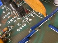
I have a orion hcca 2100 that I repaired..... partially. The mute mosfets are not getting turned on, I have the opamp output but the mute fets off..no output. does anybody have had this problem. Any help appreciated. When I remove them I have output.
It might be a good idea to have a "What are you watching" thread Like the music thread, Only linked to AVI which seems to be taking over the "Just music Idea"..
Perhaps it could be a thread on its own like the music thread?..🙂
I'll explain right away that this is not about any kind of design, vector, cutting, milling or anything else - I have any design and drawing program for work experience and staying in a home made creation, I wanted to understand from you, crossover experts, what you use and how you make them.
I made one with the multi-hole base, but I won't show it to you otherwise you'll laugh until late, very late 🙂
I am trying to put together a quasimodo test jig. Does anyone have a board they could spare? I can order them no problem, but wanted to check here first. thanks
I am a total noob at electrionics and audio gear. I'm hoping to learn some new stuff by working on this first project. Basically I have an Audio Technica LP60X that outputs a signal at around 36dB LINE (100mV @ 1kHz) and currently it goes to a set of Logitech desktop speakers with a max input rating of 10W and a continuous rating of 5W RMS. (I know its probably an insulting setup to any harcore audiophiles but Im working on a budget).
My goal is to create an ESP32-S3 Mini 1 controled PCB, which will act as passive volume control in between the turn table and speakers. It does not need to amplify the signal, just be able to fade out and then fade back in using the ESP's wifi function and a digital potentiometer. I did some consulting (chatGPT and Youtube) and settled on using the MCP4231 as it seems to be the only chip that can handle stero input with single power supply and SPI control. (its also cheap).
The plan here is something like this: Audio from record player --> Passive Wifi-enabled volume control --> Speakers
I have attached a schematic I drew up in KiCad. Would you be able to look it over and let me know if there are any crucial errors I might be missing? Also if you have any tips/tricks or recomendations that would be appreciated too.
My cabinet conversion is nearing completion and I am getting ready for set up.
As a newbie, I am in danger of trying too many things at the same time and therefore getting confused. So I have to try to move in clear, simple steps, in the right order of priority, with clear objective, constraints and method for each.
So far I have the following plan which is limited by my current level of knowledge. I was mainly using this thread by @AllenB for guidance (although it goes more into passive filter design and is not specific to active filters) and I am now trying to make it more specific to active/DSP. I also used advice given in the build thread so far by @Busdriver02, @svp, @temp25, @Juhazi, @hifijim. I would like to build this guide so I can follow it myself and also make it available for others to use with DSP-based 3-ways. Would appreciate if experienced people can have a look and help me put it together.
Hello all. I built a Chinese PP tube amp I have had laying around for a few months. As we know there are no instructions aside from the schematic they send with it, which isn't great.
I have the transformer marked as 110v, same or similar to the one in post #98 in the above link. I am still not sure how to wire the primaries or the 2 yellow and one black (Yel-Blk-Yel). They show going to the 6.3v/0 and I assume the black go to chassis ground. And the primaries? Red-Blk/Red/Blk. I see only 6+ volts on one of those primaries. Are they marked incorrectly, perhaps?
This is a very compact and cool looking TDA1541 DAC for your consideration.
I am providing quite a bit of details, so please read with patience.
The first thing to note that the TDA1541 chips are de-soldered from Cambridge Audio CD2.
I have obtained it from a very kind member here, I only paid for shipping from UK : TDA1541
The chips came with the boards, with aluminium plates glued on as heatsink or other purpose that i may not know.
As i removed the aluminium plates, most part of the prints on the chips were stucked to the adhesive used.
The chips were all removed by me, no pins are damaged, all in full length and clean.
If you mind the cosmetics of the TDA1541 chips, then this DAC board is not for you, I suggest you skip this post.
Here's a list of various drivers I've tested. The vast majority are garbage tbh. I don't intend to update this list or publicly rank drivers going forward though hopefully this list provides some benefit to diy builders of the world. I've ranked those which I prefer in the top section. Then beneath are those which I find "good" and below those are garbage labeled "The Ugly". There are a handful of drivers in the ugly section which I intend to retest at different less strain inducing crossover bandwidths though the vast majority of my sentiment is specified here albeit a bit negative. I haven't tested every driver ever and there are certainly many gems to be tested that are not on this list.
Call it conspiracy or what you will... There's an inner circle of pagan colonialist imperialist federalist guitar worshipers who seem to hold chair as gatekeepers of various audio industry related things and speaker gear. These people may also happen to be stingy as hell. That fact aside, as such, many of the best products, high sensitivity low mms cone drivers for example, are disguised within the realm of guitar speaker drivers. Two example companies are Celestion and Jensen. Both make some fine drivers and again some junk... The ladder makes at least a couple drivers that I consider to be among the best and competitive with any I've tested. The brands which I consider to be honest, science oriented and therefore gain the rank of S tier are: Visaton, Fostex, Beyma, Mark Audio and Seas. Of similar quality though presenting a less consistent and or less focused and or less updated product line are Jensen, Ciare, 18Sound, LaVoce, Kartesian, and Faital. Oberton, PHL, and Audax seem to be landfill grade. B&C, Eminence and Celestion exhibit an imperialistic monopolistic political brand identity that I deem gross and reflective of oil baron level greed and orkishness. Through the lines I observe some sort of mining union business scheme clinging to stale traditions as though somehow holy, and claiming both land rights and music as of their own invention. Celestion does make some good products available to the masses... In general my preference is for less landfill quality quantity best business practices stagnant christian values anal retentive control freak bs. Preferable would be zero corporate influence in favor of scientific progress, though also an acceptance that we're dealing with mundane devices here, and if applicable achieve quality through real innovation.
Here's a simplified list of my favorite drivers in order of preference from best to worst. With regards to crossover frequency and driver size selection I am mostly optimizing for midfield level playback.
Here are two additional lists of drivers which I tested for my project. The "Good" list are drivers which I found to be very performative though inferior to the my "Favorite" drivers. And the "The Ugly" are drivers which I found to be inferior:
I have in my pre for b+ two 100mf 400v film caps installed. I want to bypass them with 0.1 mf film caps which rated 250v. In the b+ rails i have in tubes plates 217v dc measure exactly. This voltage is after the ECL82 and goes to tubes plates . The transformer winding output is 230v ac and i suppose (didn't measured) that is approximately the same after the diodes and to the 100mf caps.
My question is..... Is it safe to bypass them with 250v caps? Is it enough 250v . I ordered them and i didn't pay too much attention by mistake to the voltage rating.
I will post pic of my external tube preamplifier PSU.
Also pics of the actual pre inside. 12au7 12at7 per channel. All hook up cables are pure silver, dact pot, visay and takman film resistors and all film caps , tube sockets of teflon and pure ofc cooper , rca jacks pure cooper. Aslo in the PSU the heaters regulators are SPARKOS discreet regulators SS7812. The construction is pure dual mono from pre to psu. The preamplifier WAS KORATO KVP20 dual mono version from factory. WAS. ........ Now is something else . Its completely reconstructed and rebuilt but the circuit remains as it was from factory and the actual values of all the new and higher quality parts (resistors caps diodes regulators) also as it was from the factory.
Hallo DIY audio. I am a new member from Greece. My background is a Physics degree and my hobby is audio electronics. I am trying to build a Goldmund mimesis 3 and so far I have build the power supply using 2 transformers of 300VA each. Is somebody aware where I could find boards for the above amplifier?
Thanks
The dreams and hopes of men are powered by addiction
And who am I to say that this is an affliction
When everybody gets suckered in and lives their lives like fiction
Writing their own stories of success
They say they want you for your colourful evocation
The way you turn a cliche into a sensation
But all they ever wanted was that same vibration
The one that shimmers round success
Success success
All you ever need:
Success
You can't be happy while someone else has a fistful
They glow from TV screens healthy strong and fiscal
And everybody slaps their back while you're alone with a wristful
Jerking to the rhythm of success
I'm working on a setup to measure amplifier noise output, SNR, crosstalk etc. and see that a number of people are using a USB soundcard as the basis of such a setup.
Can anyone comment on improvements to the following setup?
Scarlett 2i2 USB interface (this seems to be a popular USB interface). Are there USB interfaces with a better noise floor than this one (at a similar price level)?
My name is Dimitri, i am from the Netherlands.
New here because i followed a threat and wanted to give a reaction so thats why i signed up to give some tips.
I am undecided what analyzer to purchase. Currently I am using EMU0204 with SprecraPlus and for the most part it gets the job done, however when it comes to measure balance phono, it becomes tricky to get proper results. Plus the voltage range and therefore performance dependency it too large.
'This prompts me to get a new analyzer and since there are nice Audio precision on the market some system one and two at a more reasonable price. However they are old need special interface and computer and if they break it is not easy to repair.
In parallel I was looking at QA403 and I was wondering if nowadays, it is still worth to look at this older equipment as this perform as good but yet cheaper and more reliable, or these analyzers still set a standard?
How do people structure and layout their workspaces?
I do a variety of work, maybe metal for amplifier case or woodwork for speakers, also the usual home renovation, bicycle maintenance etc.
When I moved it all ended up in boxes, tolerably well sorted, like Hammers box, Saws box and so on, easy to find.
Time to unpack and layout the workshop, and "easy to find" may not be the best way to do it. For instance if I do a metal chassis I probably want a hacksaw and perhaps a soft face hammer or other metalwork tools conveniently co-located, while for speaker boxes I want the wood saw near the claw hammer and other wood tools, no use to have the wood saw next to the concrete saw.
But lots of tools are not material specific, drills for instance, or measurement tools.
One option is a kind of work flow layout with a materials input and preparation area (saws to cut to size etc), assembly area (spanners and screwdrivers etc), finish area (sanders, polishers, paint etc).
But not so suitable for ad hoc repairs and the like.
So, what do people find convenient and efficient?
Curious to have some fresh perspectives.
I have about 32 square metres at the moment but plan to at least double that.
I’ve been building subwoofers for years now, and I’ve always used car audio drivers. However, I recently started building speakers using pro-audio drivers, specifically mid-woofers and horn loaded compression drivers. I love how dynamic and clean-sounding these drivers are, so it was only natural that I decided to give pro-audio subwoofers a try.
I did some research on pro-audio subwoofer drivers with relatively low Fs (resonant frequency) and high Xmax (maximum linear cone excursion), and the Lavoce SAF184.03 stood out as a promising candidate. It features a beefy 4" voice coil and 1500W power handling. Some might scoff at the Lavoce’s 30 Hz Fs and 13 mm Xmax, but keep in mind that I plan to build multiple subwoofers in tiny sealed enclosures – at least by 18" subwoofer standards, so deep bass output likely won’t be an issue, and I’ll still be able to keep enclosure sizes in check.
I eventually settled on an enclosure design featuring generous 4" radius rounded corners even though I knew it would be somewhat challenging to make. Using 15 mm kerf-bent Baltic birch plywood not only keeps the enclosure weight in check but also is stronger than MDF, not to mention the wood grain looks very nice when stained a light color. The braces and baffle were made from 18 mm MDF.
I used a biscuit joiner to cut slots in the plywood. The two MDF braces are attached to the plywood using biscuits, essentially serving as the form around which the plywood was bent.
The braces also feature circular openings to support the heavy subwoofer motor, which probably weighs close to 15 kg (~33 lbs) by itself.
The front baffle and rear panel were painted black, and the birch plywood was stained white with a two-component oil. I lined the walls with polyfill sheets.
I placed four pillows filled with polyfill inside to improve deep bass response. In total, I used about 1 lb of polyfill per cubic foot. The gross internal volume, before accounting for driver displacement, is approximately 3 cubic feet (~85 liters), which is about 25% smaller than the typical minimumenclosure size recommended for a standard 18" car/home audio subwoofer.
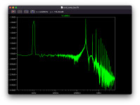
With the addition of polyfill, the subwoofer’s resonant frequency decreased from about 61 Hz to 56 Hz. The impedance curve reveals that inductance is well-controlled, allowing this subwoofer to be easily crossed over as high as 500 Hz. The nominal impedance is 8 ohms.
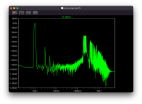
The near-field frequency response indicates a roll off that’s less steep than the expected 12 dB/octave for a sealed enclosure, thanks to the driver’s strong motor. When placed along a wall in a typical sized room, the subwoofer should deliver flat frequency response down into the mid-twenties, especially after reducing the ample mid-bass output using EQ or an AVR’s room correction capabilities.
Finally, a complete build video is available below. Please let me know what you think.
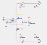
This amplifier is for you who have a headphone: 8, 16, 32, 60 or 64 Ohm impedance.
The trafo is 2x12VAC.
The MOSFET can be any TO-220 or TO-247.
For example IRFP240, IRFP140, IRFP044, IRF540. (IRF520 and IRF610 gives a little more distortion = more MOSFET sound)
The resistor should be 5 Watt.
If you have some MOSFET laying around, this project is for you.
You get good use of your MOSFET.
I have not built it. But the SPICE test shows it is a good, solid and fun design.
It works 🙂


