Optimal bias in push-pull EF output stage: textbooks and reality

Push-pull EF or 2EF output stage is probably the most frequently used output topology in class AB amplifiers. It is well covered in renowned design handbooks, like

Self, D.: Audio Amplifier Design Handbook (Newness)
or
Cordell, B.: Designing Audio Power Amplifiers (McGraw Hill)

Authors come to the conclusion that for the lowest distortion in class AB, voltage drop across an Re resistor (usually 0.1 to 0.47 ohm) should be about 22mV, as by Self below (he shows voltage between emitters, i.e. 2 x Re resistor):

DS_optimal.png


Simulators (MicroCap, LTSpice) show +/- similar values. But how about real amplifiers? Is it a general rule? My experience says that sometimes yes, sometimes no, depending on the amplifier circuit.

I am posting an example of the amplifier where this general rule does not work. It is the remake of 1969 Sinclair Z-30 amplifier:

Z30_remake.png


Re resistor (R14, R15) is 0R22. Optimal bias should be (according to Self) 23.1mV per Re. I have measured spectra at moderate power (4R7 load) for 8mV, 14mV and 21mV per Re, i.e. idle current 36mA, 64mA and 95mA. Below are the results.

8mV.png 14mV.png 21mV.png

The distortion is almost same in all 3 cases, slight differences are in high order distortion components. Something does not fit. Let's measure distortion as a function of output voltage and idle current:

THDlevel_4R7_8-50mV.png


And now we have it. It is something that we would intuitively expect. At low power, the higher the idle current, the lower distortion, because the output stage stays longer in the class A. The lowest distortion is for 50mV across Re, resulting in 227mA idle current. Now we are up to 0.48W in class A for 4R7 load (green trace). About 2.5x Self's optimal bias point. So? Isn't it better to design for lowest measured distortion, rather than follow textbook suggestions? And, BTW, this amplifier has flat THD vs. frequency up to 10kHz, measured with 90kHz BW.

IMG_1369.jpg

------------------------

Edit June 15, 2025:
There were some remarks that the amplifer under test here above was a poor one. I agree, and for this reason I am posting results measured on another amplifier.

So, another amplifier, much better than the oone here above. 3EF topology, 0R22 Re resistors, one pair, 2 x 25V supply voltage, 4R7 load - conditions are same as before. Bias voltage across Re 9mV, 23mV ("optimum") and 40mV.

Spectra:
kenn_9mV.png kenn_23mV.png

THD vs. output voltage into 4R7 at 1kHz and BW45kHz:

kenn_biaschange_thdlevel.png


We have much lower distortion now, however the same result. The "overbiased" setting has lowest distortion at low power, at higher power all settings become equal.

need help to find a 10" woofer for a 3 way vintage upgrade

Hello all
I have the sansui SP 1200 vintage speakers I have changed the capacitors. The speakers are working ok but need to ameliorate the low frequencies and replace the 10inch woofer with better one that can handle more power too.
The actual woofer (the W103 7ohms nom. 20W) is crossed at 700hz with a 3way 12dB/oct parallel crossover.
Speaker's specs :
8Ω, 92dB, 60Wats peak
it has 2 Squakwers S104 15ohms and 2 tweeters T103 17ohms
I guess i need to fine a woofer with
  • Low Qts because the enclosure is small not more than 20 liters reflex with 2 dumped ports
  • sensitivity 96 dB
  • Impedance 8oms (with not less than 4ohms drop down)
  • magnet weight 50oz ?
  • coil diam 2 inch or 2.5 cm
  • low Fs
  • freq response 30-5000Hz
The enclosure has 2 parts see file attached :
1 the woofer's part which is small in volume and is has dumping material with 2 ports
2 the upper part with the tweeters has no dumping material
the 2 parts of the enclosure are not closed there is a gap behind above the woofer
Also the crossover does not have any filter on the woofer so might need to add an inductor?
Most of the drivers I see are for professional speakers and for PA speakers and maybe not flexible for home hi-fi ? can I use one of those?
I need help to find a driver
Thank you

Attachments

  • 20180731_140347 - Copy.jpg
    20180731_140347 - Copy.jpg
    58.9 KB · Views: 72

45 SE class A Amplifie

I have a pair of Hashimoto H-20-7U and would like to build an SE Class A amplifier with sufficient sensitivity to avoid an external preamplifier.
For the tubes I am considering a EML45 Mesh
I have very efficient speakers >100 dB, therefore the two watts of the 45 is not a problem.
I would appreciate it if someone could point me in the right direction.
In the research I did I found these two schematics.
I really appreciate your help with this project!!

Attachments

  • brave_screenshot_www.emissionlabs.com.png
    brave_screenshot_www.emissionlabs.com.png
    24.6 KB · Views: 128
  • screenshot-1750434621321.png
    screenshot-1750434621321.png
    490.2 KB · Views: 129
  • yamamotoA-08S.jpg
    yamamotoA-08S.jpg
    91.5 KB · Views: 129

2-Way MEH build

After months of research on Multiple Entry Horns, I’ve decided to build my own. While there are some excellent designs available, I’ve decided to design my own due to size constraints and budget limitations. My goal is to build a complete system for under €2000, including drivers, amplifiers, DSP, materials etc.

I’ll be documenting the journey and sharing the lessons I learn along the way. Since I’m new to this, I’d greatly appreciate any feedback or suggestions for improvement.

For those unfamiliar with Multiple Entry Horns (also known as Synergy or Unity Horns), I’ll include some resources below. In this post, I’ll refer to them as MEHs.

Why Synergy horns?
Synergy Calc V5
Synergy Patent
SynTripP: 2-way 2-part Virtual Single Point Source Horn | diyAudio
Scott Hinson’s MEH

The Design
Designing this project involved plenty of trial and error with drivers, designs, and Hornresp parameters. First I was going to build a 3-way MEH using four 4” drivers and two 10” drivers per horn + big subs using 15” drivers. However, when I discussed this with my better half, she wasn’t happy with the big size. So I changed it to a more compact design: 30x30cm 2-way MEHs paired with subwoofers.

For the 3-way MEH I got ideas and insights from Syn 9/Syn 10 and Cosynes, Scott Hinson’s MEH and SynTripPs. After deciding to go with a smaller horn, I began exploring more compact designs, such as: Two way synergy Horn, Portable Battery Powered MEH Build and others.

Size
Using Synergy Calc , I calculated the size and parameters for Hornresp. According to Bill Waslo: “with horns, bigger is better!”. While I would have preferred larger dimensions, I had to consider WAF, so I settled on a 30x30cm horn with an 80° coverage angle and horizontal pattern control to 850 Hz. After reading this discussion I changed the S1 value to 5.06 to match the CDs opening area to get a more precise Hornresp Simulation..

Screenshot 2024-12-09 at 20.59.39.png


Drivers
Hornresp is a fantastic tool for modeling speakers, big thanks to David McBean for his contributions! After countless evenings testing various drivers and parameters, I settled on the following components:

Compression Driver - FaitalPRO HF108 (8Ω) I chose it because it works well in short horns and wide dispersion waveguides and people seem to like it a lot. The recommended crossover is 1300 Hz, which is what I’ll go with in my design.
Midrange - 2x FaitalPRO 4FE35 (8Ω) in parallel - they simulated well in Hornresp and have been used in some MEH builds before.

Hornresp parameters

horn dimensions.png
Mid driver.png
frecuency response.png


3d printed horn
The inner section of the horn (shown in light grey in the 3D rendering) will be 3D-printed, while the outer flare will be constructed from 2 sheets of 19mm MDF with a dispersion angle of 130 degrees

The HF108 compression driver has a 31-degree exit angle, so the horn starts with a matching 31-degree angle and gradually transitions to an 80-degree angle at the midrange entry point.

To minimize unexpected cancellation notches, the inner corners of the horn are smoothed with 2mm rounded edges.

speaker2.jpg


speaker.jpg


Mid driver Port location:
From Why Synergy horns?:
In a synergy horn we put the tweeter at the horn apex, easy enough, but how do we know where to tap in the midrange and bass drivers. We use the rule of 1/4 wavelength. So if we want to cross over from the midrange to the tweeter at 1200 Hz, we would have to tap in at 340/1200/4= 7 cm (2,8"). At the same time the cross sectional area (CSA) at the tap in point with in the horn. should be no bigger than in circumference, than the highest frequency being used in the bandpass. So at 1200 Hz the wavelength is 28,3 cm, so CSA can be no bigger than 28,3 cm, otherwise the hornwalls will no support the frequency. Same thing applies for the bass drivers. If we want to x-over from bass to midrange at 400 Hz, then the axial distance from the apex to tap in is 340/400/4= 21,2 cm (8,3"). This 1/4 wave rule makes sure that the drivers bandpass, is cut off and basically acoustically self terminate. What happens is that the frequency at play, for instance at 1200 Hz, travel toward the apex of the horn and then back again, but this time, 180 degrees out of phase, so a cancellation notch occur. In this way we can acoustically short circuit the bandpass, smart. What this cancellation notch will also do, is to acoustically lower the harmonic distortion above the cancellation notch. This effect can NOT be done electrically ONLY acoustically. This cancellation notch can be as big as -30 dB, so harmonic distortion is also lowered -30 dB. The result is a much cleaner sound, compared to other speaker designs.

I’m crossing between the mid and the compression driver (CD) at 1300 Hz, which means the port holes for the mid drivers should be within 6.596 cm (calculated as 343/1300/4) of the CD’s exit.

I’ve been wondering if the critical distance is measured from the mid ports to the CD’s acoustic diaphragm or its exit. The CD’s exit seems to work well in previous designs posted here, so I decided to go with that. This approach also simplifies placement by allowing the ports to be positioned farther out.

To ensure I stayed within the critical distance, I decided to shorten L12 slightly (the distance between the CD’s exit and the plane of the mid-entry ports). L12 is 4.28 cm, meaning the centre of the mid-entry port is 5.84 cm from the centre of the CD’s exit, so it’s well within the required 6.596 cm for the crossover.

The circumference of the cross-sectional area at the tap-in point is calculated as 6.531*4=26.124, which is close to the wavelength of 1300 Hz.

However, when I model it in Hornresp, the cancellation notch appears well above 1300 Hz, and the mids start to roll off around 2000 Hz. I can increase the distances well above 6.6 cm before I get the cancelation notch near 1300 Hz. I’m not sure if I’ve missed something in my calculations and the measurements may differ when I measure the build speakers.

Mid driver Vrc:
I made the Vrc (closed rear chamber volume) fairly small 2 L in total (1L per driver). I still haven’t figured out how I will limit the chamber volume. Using tubes like those in the Cosynes would be challenging due to the distance between the mids and the compression driver.

Mid driver Vtc:
I didn’t feel like I needed to minimize the Vtc (throat chamber volume) as the mids can play high enough frequency already. Making it smaller using cone plugs seems more beneficial with bigger woofers (like on the SynTripPs) and also the B&C 4NDF34 which have been used in some designs. For now I’ve estimated 50cc per driver, but will measure the volume when I receive them. I might adjust the sizing after doing the final calculations with the correct volume.

Mid driver port size:
There are 2 entry ports per driver, 4 in total. The entry points are frustrumised, 2.76 cm in diameter closest to the driver and 1.95 on the inside of the horn, which translate to Ap1 of 24 cm² and Ap2 of 12 cm².

The ports are relatively small, with port velocity exceeding 17 m/s when played above 105 dB below 200 Hz. These are meant for home hi-fi use, so I don’t plan to play them too loud. I also don’t want to make them too big, so they affect the CD’s output. The ports are placed next to the corners to minimise the effect they have on the CD.

Vertical drivers:
This is something I haven’t seen mentioned often, and it seems to be overlooked in many MEH designs. I will place all the drivers vertically, on the side walls of the horn, to avoid driver sag.

2. All drivers needed to be nearly vertical. The suspensions of a lot of home drivers will take a set over time if stored horizontal...I've seen it way too often. Since I'm using relatively inexpensive drivers I wanted to avoid this since I don't plan on building myself new speakers every 5 years or so. Source

Ported or sealed box:
While I was designing the 3-way MEH with 2x 10” woofers I tried modeling the low drivers in both ported and sealed box. I ended up choosing sealed after reading Arts comment from the SynTripP thread.
In retrospect, the 3dB gain the ports provide around Fb are probably not worth the -3dB 350 to 475 Hz and-10dB cancellation at 700 Hz. That upper cancellation requires more output from the HF driver to “fill the hole” in response they cause. Most 3" diaphragm drivers are already excursion challenged in the acoustical crossover range.

To sum up, don’t bother with cutting the port holes, leave the cabinet sealed 😉

Subwoofers:
I haven’t decided on the subwoofers yet.
I’m considering adding two subs within the same enclosure as side-firing woofers in a push-push alignment. For example, two GRS 8SW-4HE drivers in a sealed configuration with a ca 42L volume. Here is a promising recommendation for these woofers.

If I go with this approach, I might decrease the vertical coverage angle of the MEH horn to 60 degrees to make space for the woofers below the horn. I guess it would be good idea to have the woofers close to the horn, within ¼ wavelength of the crossover frequency, but have also read that it doesn’t matter very much for frequencies below 100 Hz.

Adding the subs in the same enclosure would significantly increase the height of the enclosure, which may not pass the WAF. Alternatively, I could build a separate subwoofer placed approximately 1.5 meters away

Is it better to integrate side-firing subwoofers within the same enclosure or should I make a separate enclosure, which would need to be ca 1.5m away? I’d appreciate any feedback or suggestions on driver selection!

side firing woofers.png


Amplifier and DSP:
As I don’t own any of the parts needed I have the opportunity to build the whole system from scratch.

The TPA3255/51 amps seem to offer great value for the money.
I’m looking into: Fosi ZA3, AIYIMA A70, Topping PA5 II and the upcoming 3e audio amps. I haven’t decided yet and would appreciate any recommendations.

Finding a DSP solution that fits the budget has been tricky. High-quality DSPs can be expensive, while the cheaper options often come with limitations.

I’ve decided to go with a Raspberry Pi 5 running CamillaDSP. For the DAC, I’ll start with the cheapest option: the AliExpress cards mentioned in this guide. RPi 5 Quad Stereo Sound with PCM5102A – Simple DIY Electronic Music Projects. User dptucunduva has had good results with it.

The reasons I chose it are:

It’s cheap and has good potential for upgrades. I can switch out the DAC module for a proper sound card like the Motu Ultralite mk5.
It’s a very flexible system, the Raspberry Pi can act as a streamer and allows for lots of add-ons like a remote controller, Those who use CamillaDSP seem very happy with it.
HiFiBerry DAC, which uses the same DAC chip seems to be decent according to the measurements here. I’m not expecting any fantastic results but see it as a cheap solution that has all the active crossover functions needed.

Next steps:
The CD and mid-drivers are on their way, and I plan to begin 3D printing the horn in early January. In the meantime I’ll focus on refining the horn design, adding mounting holes, figure out how to do the right vrc size. I also need to decide which amplifiers to use and start building the Raspberry Pi DSP. Additionally, I’ll work on designing the subwoofers and determining whether side-firing woofers are the best option.

Any suggestions or input would be greatly appreciated!

Denon DN-X900

Hi
I have a Denon DN-X900 mixer that has 2 or 3 channels that I cant get sound from. I think it's two. ch3 and ch4.
In these mixers all the inputs can go through all channels ,it's a case of selecting the input you want on that channel.
I was looking at the Schematic and it doesn't look obvious to me what could be the source of the problem.
I don't have a scope so it might be difficult to find the cause of the fault.
I've had the mixer for a while. I don't have it open at the minute as I want to see where the signal goes first.
Last time I had it open I had a good look but couldn't work it out. I checked ribbon cables and a few other things.
Maybe someone here has repaired one ,or had a similar problem with these.

Cheers

Schematic
Service Manual


denon_dn-x900_dj_mixer.jpg

Something to lighten the mood

So I kick off early today like many are doing during this C19 crisis and I thought I'd do a little housework before the Mrs. came home. I started making the bed and I noticed a pillow was missing. I look around and see it on the floor at the end of the bed. Only problem was, it was moving. It seems that little Bingo was playing hide and seek with Daddy and had now trapped himself inside. Lifted him onto the bed, freed my little prisoner and went onto finish my work. It was funny enough that I thought I'd share because I think we can all use a little something to help us smile these days.
Cheers.

Attachments

  • IMG_0094.jpg
    IMG_0094.jpg
    112.2 KB · Views: 2,581
  • IMG_0096.jpg
    IMG_0096.jpg
    104.2 KB · Views: 2,528
  • IMG_0097.jpg
    IMG_0097.jpg
    95.6 KB · Views: 2,604

The Orphéus Project...

Hello everyone,

With this thread, I would like to introduce and share with the community the Orphéus audio project...

It's a fairly ambitious project in both form and content, and it includes many unique features that I would be happy to detail further.

The main objective is to create a complete audio reproduction system using tubes and valves, and incidentally, to inspire members and/or music lovers with a "do-it-yourself" mindset and a minimum of experience in electricity and/or electronics.

The roots, as well as the various configurations adopted in this project, as well as its implementation, stem from a specific design philosophy and adopt certain principles based on convictions and experience.

The Orphéus system is composed of two devices. The first, which is also the heart of the system, is a transformer-based SE preamplifier, also known as a WOT (With Output Transformer) preamplifier.

Its main hardware features are:

  • 3 x RCA line inputs switchable via a rotary switch and micro relays
  • 2 x RCA phono inputs, switchable MM/MC via Hashimoto HM-3 step-ups
  • 2 x split RCA line outputs + switchable XLR (balanced)
  • SE line stage with a 6n6p/ecc99 + Monolith Magnetic's SL-01/20 transformers
  • Tube phono stage (2 x ecc83 + 1 x ecc82)
  • Switchable dedicated headphone output
  • Motorized TKD potentiometer
  • Dual mono VU meter with modulation display
  • Panel meter for bias control

Below is an illustration of the device in progress...

przoam22.jpg


I think you've all guessed by now that the second device is, of course, the Orpheus power amplifier...

The latter uses a pair of 300B directly heated triodes in a single-end configuration with an inter-stage transformer. The power supply uses a valve with a timer and Pi RLC filtering per channel.

The standard driver tube, like the preamplifier, is a 6n6p/ecc99 dual triode. A specific board was developed for the latter. It is paired with a pair of IT-01/25 inter-stage transformers.

A second driver board with an identical footprint was developed. It uses a tube with beautiful precision mechanics, the D3a. Its Mû is almost 3 times higher than the 6n6p/ecc99, and can therefore, on its own, make any 300B triode swing beautifully.

In this regard, two specific driver cards are of course necessary.

ampli_22.jpg


The amplifier also includes a Panel Meter to display the effective bias voltage of each power triode.

I also integrated a volume potentiometer with a bypass to make the amplifier independent if necessary.

Here are the main points of the Orpheus Project.

To be continued...

Greetings, Tony
  • Like
Reactions: DATIR and ng5921

2x100W TPA3116D2 (2 chips, each in PBTL)

Hi guys,

Among all the TPA3116D2 hype I've seen many single-chip stereo and mono boards (2x50W or 1x100W) as well as dual-chip 2.1 boards (2x50W + 1x100W).

I don't really need a sub but I'd like to have some extra power for peaks, especially when driving 8ohm speakers. What do you guys think about this board?

2 100W TPA3116 D2 Dual Channel Digital Audio Amplifier Board 12V 24V for Arduino | eBay

Does it look like I can get decent quality or would it be more advisable to get one of the well known boards in the wiki?


Thanks!

TDA7293 kit vs MJ15024 (QUAD 405 kit)

I have only studied tube amplifiers, but I am interested in transistor amplifiers this time, and I want to study them. The problem is that I know nothing about transistors. I want to buy a kit for under $50 from AliExpress and make it as a beginner. Currently, I am looking at the TDA7293 kit and the Quad405 kit. Which one sounds sweeter? Or is there a kit that you recommend for under $50?
1000037169.jpg
1000037171.jpg
  • Like
Reactions: Franz Shottky

For Sale High end phono MM preamp

I am selling a very high-class MM phono preamplifier made according to the design of T.Giesbert from Elektor 7-8/2016.

Preamplifier in a housing with dimensions 13x6.5x25 cm (width x height x depth), running, functional.

The opamps used are very good LT1028 and LM833.

Power supply is 230V AC.

The casing is without any scratches.

The price is 160usd + shipping costs.
IMG_20240307_145625.jpg
IMG_20240307_145719.jpg
Bez tytułu1.jpg
Bez tytułu2.jpg
Bez tytułu3.jpg

Simple Low Power Amplifier with OPA134 Through Holes Project

OPA134 is a good opamp. It is very stable. It has rather low distortion.
Here I use it to control a power buffer of EXICON MOSFET.
Supply should be a 2x12VAC transformer. Giving like 2x15VDC rails.
Data:
Bias should be like 500mA. This means power to cool is like 15 Watt per channel.
THD 0.00015% at 1 Watt 1 kHz into 8 Ohm.
Upper frequency 450 kHz with the input filter.
Max output a bit more than 9 Watt into 8 Ohm. Of course more into 4 Ohm.
Gain margin is very good, as is Phase margin.

Enjoy 🙂

OPA134 Power Buffer_01.jpg

For Sale Micro-Audio SMPS600-R2 (+46Vdc) power supply

The Micro-Audio SMPS600-R2 is a high-quality, unregulated 600W switching power supply designed for audio applications. It offers a single-rail output of 46Vdc. SMPS was bought few months ago and it is in perfect working condition. Dimensions are 187x123x50 mm and weight is around 800g.

This SMPS is designed to power various TPA3255 amplifiers, like 3e modules and others. It provides significant sonic upgrade, compare to cheap SMPS.

I paid around 200 EUR (all shipping costs and custom fees included) to import it to Slovenia (EU). My price is 125 EUR + shipping + PayPal fee.

Attachments

  • Micro Audio.jpg
    Micro Audio.jpg
    476.3 KB · Views: 162

For Sale Set of capacitor board for single supply SMPS

I have for sale a set of two additional capacitor boards. They were designed to improve performance of single rail SMPS when powering D class amplifiers (3e, Sylph Audio...). Dimensions of the board are 95x50x40(height with spacers) mm. Each pcb board consist of:

1x Nichicon FW 1000uF 63V
2x Nichicon FW 470uF 100V
1x Nichicon KZ 100uF 100V
1x Mundorf 1uF 250V foil capacitor


Price is 25 EUR (for set of 2) + post costs + PP fee

Attachments

  • cap board II.jpg
    cap board II.jpg
    424.6 KB · Views: 100
  • cap board I.jpg
    cap board I.jpg
    358.9 KB · Views: 97

XEN SHPP -- Simple Headphone Protection

With dynamic headphone now getting more and more expensive,
and the many high bias class A amplifiers around, including two from us,
it is perhaps a good idea to have a protection circuit for headphones.

The difference to a loudspeaker protection is of course the lower trigger voltage level (e.g. +/-80mV DC).
This requires a different treatment for the DC sensing stage.
Here is our solutions.
Works first time as intended. 😉

http://xen-audio.com/documents/SHPP/XEN SHPP V1.pdf


Patrick

.

Attachments

  • 160607 SHPP Proto1 Top.JPG
    160607 SHPP Proto1 Top.JPG
    284.4 KB · Views: 2,556

NAD C326Bee goes into standby although an active signal is present. Any idea?

Hi there,

a couple of months ago, I reported that I could re-animate my NAD C326Bee from turning on and forcing a specific input to be chosen.

Since then, the amp was working perfectly, but then since yesterday, a weird behaviour occurs:
* The amp is working with a valid input signal, and is set up to have the auto standby function in absence of signal. Roughly after 1 hour, it goes into standby (real standby, amber LED. Not protection with red LED). I managed to reproduce it with different inputs.
*When I de-activate the auto standby function, I could not reproduce the problem.

In other words, it seems that the auto standby function is corrupted, and is triggered erratically when it should not.

Did anyone have already such a issue? And if so, what would be the solution?

Cheers.

Port placement inside of a small bass reflex cabinet

Hi,

I am working on a project where the cabinet is a small bass reflex (~5.3 liters).

Space is tight, and I would like to give the reflex port close to 1 diameter clearance from the inside walls. The port internal diameter is 32 mm (1-1/4 inches).

I have 3 options in mind - have attached rough illustrations of each (not drawn to scale).

First 2 options use a straight port attached to a 3D printed flare attached to a 32mm inner diameter PVC pipe. The third option uses an PVC elbow joint which is attached to the 32mm pipes on both ends, and one of the pipes is attached to the flare.

Would be good to hear what the good folks of the forum think. 🙂

Attachments

  • Port placement 01web.jpg
    Port placement 01web.jpg
    17 KB · Views: 8
  • Port placement 02web.jpg
    Port placement 02web.jpg
    17.6 KB · Views: 6
  • Port placement 03web.jpg
    Port placement 03web.jpg
    18.4 KB · Views: 6

TPA3255 Reference Design Class D Amp with PFFB

836851d1587609199-tpa3255-reference-design-class-amp-gb-67aa1113-6c7f-4ff0-91da-9f8655028f17-jpeg


I wanted this to be one of the first products I highlight in my new forum. This amp started as a GB in this thread.

TPA3255 Reference Design Class D Amp GB

There was a second GB here:

XRK RTR TPA3255 Reference class D Amp GB2

What can I say, this is a superb sounding amp. Quiet, powerful, dynamic, non fatiguing, low distortion.

JPS64 created a masterpiece with his signature symmetry, via stitched ground planes, and ultra short high current traces. The board is 2mm thick, 2oz copper, ENIG finish. Assembled in California using premium genuine Mouser-sourced BOM. Each amp is individually tested on an Audio Precision test stand at the factory and then sound quality tested by myself before shipping.

Many people have assembled this amp into a nice chassis and everyone loves the sound. With the right PSU, the amp has the distinction of being the quietest amp I have built. You cannot tell it is on with ear pressed to the speaker cone. Just silence.

I hope folks will share their builds here. Or feel free to ask technical questions.

Redjr made on of the nicest implementations. More here.

attachment.php


Vunce made an awesome build with a linear PSU with an LT4320 Ideal bridge rectifier amp on a plank here:
904076d1608713740-xrk-rtr-tpa3255-reference-class-amp-gb2-5156d2b9-b705-46d9-ab85-281f3aeb3b63-jpeg


For best results, this amp should be paired with the BTSB balanced buffer which provides selectable gains (0dB/6dB/14dB/20dB) SE or Bal input and SE and Bal output. Since the TPA3255 with PFFB only has 15dB gain, it needs a preamp with about 14dB of gain in order to play music to its maximum levels. The BTSB is a superb preamp design by Jhofland. It started as a GB in this thread. Here is the panel mount version of the BTSB:
935523d1616654517-btsb-buffer-se-bal-se-bal-buffer-gb-btsb-v1-21p-opamp-test-jpg


Those of you who know me, know that I hate casework (chassis building). This most of my amps are “plank” amps. Amps on a plank of wood. Only the most special and deserving of amps get a chassis. Well this amp is one of those amps. More to come...

Edit Jan 31, 2023: video on how to setup and connect your amp module for the first time.

Attachments

  • 4814ECD3-5B8A-4933-BA8D-666FAE3FE91B.jpeg
    4814ECD3-5B8A-4933-BA8D-666FAE3FE91B.jpeg
    455.5 KB · Views: 11,684

Coaxial Compression Driver DIY (CCDIY) discussion

Dear Community,

I recently watched a video about the B&C coaxial compression drivers. After looking them up i was shocked how pricey they are. Then i thought: can't we make our own coaxial compression driver with conventional cheap drivers/parts?
When thinking about the concept i became more and more excited to try.
Directivity control provided by a horn + point source behaviour like a full range/coaxial driver = why not?

Let's discuss the possibilities and try to succeed!
overall.png

Martin Audio Effect 5s: A bigger cabinet? Sealed vs ported

Have been playing with a set of ex-cinema Martin Audio Effect 5s

https://martin-audio.com/downloads/archive/datasheets/Effect5datasheet.pdf

They're a 2 way design with a horn tweeter and a 10" woofer in a 35 litre ported "reflex" enclosure. They're designed for use as surrounds in a cinema - originally wall mounted, the cabinet is a trapezoidal shape so the drivers are angled downwards towards the listener.

They sound pretty nice. Very efficient and "fast", wide dispersion, great dynamics, loads of volume and impact. Being critical they're perhaps a bit boom and tizz in balance, not much in the way of deep bass (but plenty of punch and midbass) and perhaps a bit sucked out in the midrange /presence area. Specs claim 75Hz-20kHz ±3dB which sounds about right to me.

The shape and orientation of the cabinets is such that stand mounting is difficult, so I've been wondering whether they could be improved with some new cabinets, either large standmounters or floor-standing. I'm fairly sure that more rigid, internally braced construction and a little more care in damping/lagging would bring about improvements but am also wondering whether bigger, possibly sealed cabinets would offer better bass extension and clarity.

I can't find t/s measurements for the driver but it appears to have a relatively compliant suspension and low-ish resonance which makes me think it might work OK in a larger sealed box. I'm fairly sure these 10" woofers are capable of better bass than they're currently providing.

Would welcome thoughts on how best to proceed - I realise there's going to be a fair bit of guesswork involved so good to have some input.

SAB - class AB 2x50W/4ohm amplifier with SMPS

Small class AB 50W/4ohm amplifier with SMPS (Gerber files added - see page 2) or linear supply

This amplifier is based on Kenwood KA-5010 circuit topology, class AB with 3EF output stage and 2-pole frequency compensation, which promises to keep low distortion even at higher frequencies. I was curious how it would work and built a 1st sample 5 years ago, followed by change of the linear power supply to SMPS's this year – resulting in a considerable loss of amplifier weight 😉.

Gerber files have been released in post #25 for non-commercial, non-profit personal use
https://www.diyaudio.com/community/...-4ohm-amplifier-with-smps.386169/post-7022262

This is the circuit schematics

ka5010clone_sch.png


As a power supplies I used Mean Well RS-100-24 modules, one per channel. This is the amplifier DIY built in one of my prototype cases

SAB_amplifier.JPG

Technical parameters
  • input impedance 90kohm
  • voltage gain 30dB
  • output noise voltage 22uV/20Hz-22kHz unweighted
  • output power 2 x 50W/4ohm
  • THD < 0.002%/40W/1kHz/4ohm
  • THD < 0.003%/40W/10kHz/4ohm
  • minimum load impedance 2.5ohm
  • frequency response 10Hz – 100kHz/0.2dB/4ohm

Measurements of THD and THD+N vs. output power, with 4ohm load

SAB_thdnpow_1k.png


SAB_thdnpow_5k.png


SAB_thdnpow_10k.png


Measurement of THD and THD+N vs. frequency at 20W/4ohm

SAB_thdnfreq_20W.png


Distortion spectrum

SAB_spectrum_1k.png


LTSpice files

P.S.: the amplifier has been re-measured with linear power supply 2x25Vm post #50, https://www.diyaudio.com/community/...-4ohm-amplifier-with-smps.386169/post-7031738

Attachments

  • SAB_cirsim_ltspice.png
    SAB_cirsim_ltspice.png
    49.1 KB · Views: 658
  • SAB_loopgain_ltspice.png
    SAB_loopgain_ltspice.png
    9.2 KB · Views: 830
  • SAB_kenwood.zip
    SAB_kenwood.zip
    5.7 KB · Views: 206

Sonics by Joachim Gerhard cabinets and kits

We have 120 pairs of very nice, professionally made Sonics by Joachim Gerhard cabinets in stock.
The models are : Anima, Argenta, Arkadia and Oumnia.
We have various colors like Black Ash, Cherry, Nutbush and Zebrano.
I sell each pair for 400,- € plus transportation.
Some cabinets have small scratches and dents. I sell them for 350,- € per pair.
With the cabinets comes a circuit diagram and a list of components you have to buy to complete the speakers.
I redesigned the crossovers and sometimes made new choices concerning the drivers.
The result are speakers that are even better then the famous originals.
For around 800,-€ you can own worldclass loudspeakers with a little work of your own.
We also offer ready made speakers for 900,-€ each type.
I will post photos and more information soon.

Towards a wideband non switching Auto Bias power amp

Syn08 (Ovidiu) said this about implementing an Auto Bias loop here:
" I haven't see a solid non switching full solution for the entire audio band, but only partial improvements over the standard solution of an acceleration cap (100nF, in your case), which is not a solution for non switching, but only a bandaid to limit the effect of the crossover mess.

Part of this lack of solutions is of course keeping the complexity within reasonable limits; Edmond's solution mentioned above, in despite of it's stability issues, is already a rather complex circuit, and I don't think anything simpler could be designed and successfully implemented."

Well, there's the challenge. A wideband non switching Auto Bias amplifier circuit that works, doesn't oscillate and blow up, and is not too complex.

To start this thread I'll post some of my findings from simulations of the LT1166 Auto Bias IC, as well as Class-i and Edmond's AutoBias2.

Feel free to post any of your ideas and simulations.

And if anyone has built a successful amplifier using an auto bias circuit then we'd love to hear how you did it, etc.

Cheers, Ian
-------------
Edit: Post summary (Edit: most recent first):
Post 303 Shows 3D views of a PCB for Post 302 circuit (now called Topology 4).
Post 302 The LT1223 again but now driving MOSFETs to demonstrate the autobias loop allows plug-in interchange of BJT's and MOSFETs. Interestingly, the MOSFET's achieve similar high BW with less drive current so 2 pair instead of 5 pair TO-92's can be used.
Post 301 The previous LT1223 CFB opamp with a CFP autobias loop is OK for 16MHz(tbc) without the CFP output stage, instead the discrete HV booster is paralleled for 50mA drive to the power transistors with a +/-9V auxiliary supply.
Post 300 The previous CFP BJT autobias loop is OK for 4MHz(tbc) with a LV LT1223 100MHz CFA with a discrete voltage booster giving low distortion.
Post 295 Bridge and current drive is easy with a HV opamp, where one load terminal is tied to input common (grounded bridge) with a floating PS.
Post 291 Current drive with a HV opamp is very easy using a resistor in series with the loads cold-side for feedback to the opamps inverting input node.
Post 287 CFP BJT autobias loop is OK for 100kHz with a 33 Ohm base pull-up to 9V. Allows a low input current (1mA) drive using a HV opamp (OPA455) with a split rail standard power supply.
Post 282 Only THT with current drive for 4 ohms suggested by Pawel.
Post 281 Current drive version for 200W into 4 ohm, Rout 500 ohms and 0.02% at 1W. Uses 2x OPA1656 LV 100mA opamp drivers.
Post 277 Class-G bridge 800W 4R using 4 slices per side for 20A peaks. Idle dissipation is reduced using Class-G plus McPherson's dissipation diverter.
Post 274 Bridge version for 400W 8R is DC input and DC output. Usescapacitance multiplier with McPherson's dissipation diverter.
Post 271 Mark Johnson query: What if the output capacitor divider capsare not exactly the same? Answer: the voltages equalise quickly due to the amps low output resistance.
Post 269 Power supply circuit to check startup with no dc blocking capacitor. Simulation shows no startup or shutdown transient to the loudspeaker.
Post 267 Input stage level shift with no dc blocking input capacitor.Uses an opamp with a -5V rail and a mirror input stage level shifterwith no signal.
Post 266 simulation using ZXT757 and ZXT857 300V complimentary pair for input stage level shift. Bias trimming calculation for output centering.
Post 257 simulation using a level shift input stage rather than a isolation transformer, allowing a standard non-floating power supply.
Post 256 mr_jj pointed out that Kenpeter back in 2010 had placed a resistor across the sensing diodes between the emitters of the power transistors to make it non-switching Class-AB! My hat is off to Kenpeter. I mention my independent finding in Post 202. The Dadson's circuit found in Post 44 here from his AES Oct 1980 article shows the same autobias sensing diode topology using a Rush spreader arrangement but with Darlington power transistors, but no resistor across the sensing diodes.
Post 254 Bench test using thean OPA1656 100mA opamp to drive power transistors with autobias without discrete driver transistors.
Post 244 Bench tests of a single channel amplifier shows -60dB THD using MUR1615 diodes and biased at 250mA. F-3dB is slightly over 100kHz.
Post 243 Shinichi Kamijo "simple TL bias" circuit is similar topology to my autobias but with a follower output stage and a non-floating power supply.
Post 235 Bridge version bench test. Two floating power supply amps on one supply, where one amp uses a small transformer to isolate the input signal.
Post 222 Tutorial on the floating power supply transconductance autobias output stage. More in Post 245 and Post 251.
Post 220 Using MUR1615 TO-220 power diodes instead of Schottky diodes gives excellent linearity. Bias can be trimmed by two resistors to 9V rail instead of two CCS's (simpler and less error prone).
Post 215 Using MJE3055 TO-220 as diodes instead of Schottky diodes.
Post 210 thru Post 214, Post 217-219. Option of using many (8-10) 1A silicon diodes in parallel per side instead of Schottky diodes so no need for a bias trim pot.
Post 205 FDC6321 CMOS stage allows high current drive without a CFP output stage.
Post 203 A prototype PCB allows stacking of up to slices (3 pair of output transistors).
Post 202 Using a HCU04 CMOS input stage with a CFP output transistors so only 1mA is needed to drive the autobias transistors. The CMOS input stage provides some gain and soft clipping and the option of thermal-SOA protection by dynamically limiting the clip level (more in Post 204). Introduced R13 across the power diodes to provides the keep-on current of 18mA in Q1 and Q2 - even when clipping. Eureka!!
-------------------------
Edit Feb 2025. Overview of development: Toward a Wideband Non-Switching Auto Bias amplifier
The challenge! “A wideband non switching auto bias amplifier circuitthat works, doesn't oscillate and blow up, and is not too complex”.Post1 aim 29 July 2021 by IanHegglun.
  • I have exceeded my expectations. A non-switching autobias topology – simple, stable, scaleable.
  • Two related topologies: 1) The floating supply version, and 2) The non-floating supply version.
  • Several diyAudio members have suggested that I provide a non-floating supply version.
  • Topology1. The floating supply version is the simplest, eg, Fig.1 below,100W into 8R, only 2 power transistors & 2 bias transistors, 2x3A diodes, a dual opamp, and a +/-9V 2W supply. Notice no Darlington driver transistors, instead two 100mA opamps operating in parallel. THD 0.1% 1W.
  • Autobias-MUR1615-MJL3281-OPA1656-1slice-1v2a-cct.png
    Topology 1: Completed Wideband Non-Switching Auto Bias amplifier with opamp driver.
  • Can be paralleled eg Post254 and bridged eg Posts274 .
  • Uses two output capacitors in series. They are forced to half the rail voltage by the feedback loop referenced to half the rail voltage by a voltage divider (R3,R19). They prevent DC damaging the loudspeaker. It's is simple, effective and reliable, with negligible effect on sound quality.
  • Topology2. The non-floating supply version. It is a modified floating supply version with an addition input stage where the input is now referenced to the negative rail. The input stage lowers distortion to 0.02% at 1W and a low output resistance of 50 milli-Ohm.
  • Autobias-MUR1615-MJL3281-OPA1656-1slice-shift-1v3e-cct.png
    Topology 2: Wideband Non-Switching Auto Bias amplifier with DC input and non-floating Power Supply.
  • An alternative bias circuit, see above Topology 2 dotted area, it eliminates the input capacitor which eliminates the long settling time at turn on.
  • The alternative bias circuit avoids a 3rd input stage which avoids a 3rd pole which requires careful frequency compensation. Both Topology 1 and Topology 2 do not use frequency compensation!
  • The loudspeaker is protected from DC damage by the two output capacitors in series.
  • Topology 2 can be paralleled eg Post257, and bridged eg Posts274 and Class-G bridge Post277.
  • Topology 2 has been simulated and a PCB is underway for bench test and listening tests.
  • Topology 1 has been bench tested eg Post244 & Post254 and a listening test Post157. The Topology 1 PCB needs updating for an opamp.

  • Topology 3. See Post287 and Post291.
  • CFP BJT autobias loop is OK for100kHz with a 33 Ohm base pull-up to 9V. Allows a low input current(1mA) HV opamp (LT6090-5 or OPA455) to be used with a split railstandard power supply.
  • Topology3.jpg
  • . . . . Topology 3. Wideband Non-Switching Auto Bias amplifier with DC input and non-floating Power Supply and no auxiliary ±9V supplies.

  • Topology 4. See Post301 and Post302
  • Using a LV LT1223 CFB opamp with a CFP autobias loop is OK for 16MHz(tbc) without the CFP output stage.The opamps discrete HV booster is paralleled for 50mA drive to the power transistors. The trade off is the ±9V auxiliary supply.
  • Topology4.jpg
  • Topology4. Wideband Non-Switching Auto Bias amplifier with DC input and non-floating power supply and no CFP power stage, instead the auxiliary ±9V supply and higher current opamp booster stage.

Attachments

  • Like
Reactions: X.G.

For Sale Fairchild KSC3503 ESTU & KSA1381 ESTU

This are Fairchild very hard to find KSC3503 ESTU & KSA1381 ESTU gain grade. The Hfe verified to be between 160 - 175. Minimum selling 20 pair . The complement KSA1381 ESTU is available from Mouser and plenty of those in stock, the KSC3503 is only available in D grade. One pair KSA1381 ESTU and KSC3503 ESTU will be 1.50 euro.

The prices do not include PayPal and shipping costs. Shipping from Finland. PayPal is accepted, the buyer pays the additional 5% PayPal fees. Or Payment as PayPal / Friend than the shipping costs for the EU are 9€ as standard ( PayPal friend) or 19€ by registered mail up to 100gr. Outside the EU it may vary by country. If you are interested send me a PM.

Attachments

  • KSC3504 ESTU (1).jpg
    KSC3504 ESTU (1).jpg
    209.9 KB · Views: 414
  • KSC3504 ESTU (2).jpg
    KSC3504 ESTU (2).jpg
    233.8 KB · Views: 376
  • KSC3504 ESTU (4).jpg
    KSC3504 ESTU (4).jpg
    193.3 KB · Views: 350
  • KSC3504 ESTU (5).jpg
    KSC3504 ESTU (5).jpg
    214 KB · Views: 345
  • KSC3504 ESTU (6).jpg
    KSC3504 ESTU (6).jpg
    208 KB · Views: 362

The Price of Vinyl

I was buying new audiophile vinyl in the 90s some of which are now ludicrously expensive. I suppose monetising vinyl had to come - is there anything that hasn't been monetised.

So I now I have registered with Rhino and with Mobile Fidelity. Today I got an email from MF they are doing their usual 2 x 45 RPM versions of the Eagles LPs.

I always thought that Desperado was one of the best theme LPs made and not only in the 70s', I have 3 copies.

Then I looked at the price @ $125😱. Then I looked at the postage to France $50.09😱 That means 20% TVA on the whole package = $210 plus maybe a Customs inspection charge as well = no thank you.

These are just crazy prices, I suppose copies (only 7500 will be pressed) will appear on discogs - anyone interested @ $1000?

Fully balanced MC phono preamplifier thoughts

Dears,
This is sub-thread of my turntable post: https://www.diyaudio.com/community/...eded-with-motor-and-drive.412984/post-7687982
It seems appropriate to open new one just for the preamplifier.
Since I'm waiting for motor parts to start significant upgrade of this 22 y.o. thing, I will revisit the preamp too.

So far I was using this design with 2 x SSM2017 in first stage and 2 different second stages, description is here: https://www.diyaudio.com/community/...eded-with-motor-and-drive.412984/post-7688045

For the new version, I have 3 personal preferences that I would like to respect:
  • Fully differential, I see great benefit and improvement from dropping ground of the signal path. Even still I'm using GND for referencing output voltage, but in new design I'm considering bootstrapping that with very low noise amplifier.
  • Passive RIAA EQ
  • As high as possible first gain stage, 60db (1000 V/V) seems just fine with my 0,34 mV nominal output cartridge. I do use higher PS voltage to allow for more output possibility; now +-18, next +-20V. This leaves second stage to deal with only about 20db gain.
Right now I'm making upgraded PCB with same concept, SSM2017 remain as input, second stage upgraded to OPA828.
SSm2017 specifies 0.012% THD+N at gain of 1000, I probably get it bit better as 2 amps in differential configuration will cancel some distortion. However not the best in class THD, nevertheless doubt if it is hear-able. Nevertheless SSM2017 as ancient as it is, is still unbeatable on noise performance.
Here is PCB work in progress:
1720256678366.png


Alternatives (in my thoughts) for the first stage :

2nd option is to keep configuration but to upgrade SSM2017 with better INA like AD8429 for instance, as used here https://www.diyaudio.com/community/threads/chipomatic-balanced-input-riaa.331009/post-5627780 (but this is single ended output)

3rd option is classic differential receiver (same as my second stage now) , but that would call for 4 x AD797 and cost of over 70 Euro, I see no other opamp that would fit this purpose.
1720257443572.jpeg


4th option is to use this ancient schematics and replace each AD797 with it in above schematics. Probably that is as far as low noise is possible.
Matched low noise dual transistors are rare today, but there are many dual JFET's that would do just fine here. Of course some more modern opamp would be used instead of OP27. However, this design for stereo would call for 12 dual matched low noise transistors, quite heavy on wallet.

1720258101394.jpeg


Or, 5th idea, this very fine simple circuit from John Broskie's site. Looks very tempting even the gain will be max 40db (x100), so second stage will need to deal with another 40db, but that is not major issue if below circuit is quiet enough.
1720258822196.png


I'm sure that each of these options will work just nicely (when fully developed), but what would be the best?
Any comments, thoughts, ideas?

Rohde Schwarz R&S UPL Audio Analyzer Renovation

Hi All,

I'm doing a renovation upgrade project on my UPL analyzer.

I thought to list down all the possible upgrades one can do for his/her analyzer.

Then maybe i can also learn some new stuff from you guys.

Here is the link where i'm storing all my information (Software, DOS, Service Manuals, Installation disks, Many Photos) regarding my analyzer. Feel free to look around.

R&S UPL Audio Analyzer - Google Drive

See you soon.

Kind Regards,

Bart

Wayne's BA 2018 linestage

Any thoughts or comments on Wayne's linestage presented at BA 2018?

It looks like an economical high performance design with a couple of nice options (like a beefier output if needed)

I'm a terrible designer and a slow builder - I think we wound be interested in hearing if there are any experiences or opinions yet.

Thanks Wayne!

YouTube

Attachments

  • wayne.JPG
    wayne.JPG
    51.9 KB · Views: 27,377

Waveforming with a few small sub woofers

I've been playing around with a Rolls SX45 as low pass filter into Parasound ZAmp and two Dayton Audio SUB-1000L subwoofers.

This supports the sound of the main small speakers in my small system. It sounds surprisingly good and fast. Not hugely deep, but doesn't matter, mostly I want to add some reinforcement for the small speakers.

So, now it got me... I got these little, shallow boxes standing... and they're pretty cheap. I thought about getting four or six more and building two stacks of four up front, of perhaps put two stacks of two in front and two more -phase delayed, out of phase, in the back.... sort of creating what Trinnov calls waveforming.

https://www.trinnov.com/en/subwoofer-guidelines/

WAF is not important as this is my home office and I got a door...

Getting the woofers is easy, I got the crossover and the amps... so all I will need is the delay unit.

Well.... WAF might be a factor... when she walks in and sees those woofers eight feet up on the back wall... etc...

Any ideas... have you tried this?

QCC3008 config - 1 second of audio lost - (+QCC5125, maybe more)

I am using this style of QCC3008 Bluetooth module in my car radio.
qcc3008.jpg


I've noticed when audio starts to play after silence, about the first second of it is cut off/not played. This behaviour is different from any wireless earphones I have used, which seem to wait a moment before starting to play.

Does anyone know of an option in ADK configuration tool which may change this? I recently bought a QCC5125 version of this too, which also has the same problem by default.

Just to explain why this is a problem, I have the chip in my car radio and use it for navigation.
Instead of -
"In five mile, turn left"
I get -
"...miles, turn left"

Need help : sealed Infinity Kappa Perfect 12.1

this is my first subwoofer build, hence I'm still guessing and relying on modeling software. Previously i read on my friend's built which used DVC of this subwoofer, when looking at good price of this item without breaking my wallet and good result on simulation, i think my friend had a good choice on drivers.

However they are discontinued, but I'm lucky to get second hand item - 3pcs already, looking for 1 more - but they are single voice coil version. When I put into online simulation, it seems SVC has lower Fb than DVC but double in box volume which is not an issue since this is for home subwoofer.

When i google on recomended box, most of the thread lead me to car subwoofer which ended between 1-1.25 cu.ft volume but simulation give me 2.2 cu.ft. I have no issue up to 3 cu.ft box volume.

Can i rely on software simulation for box volume? which volume should i build? i will use 2x18mm plywood with internal bracing and powered by nu3000dsp.

It will be very helpful if anyone can share any experience on using SVC of this item for home sealed subwoofer.

btw this is just for stereo music, no plan to make any home theater

Attachments

  • Screenshot_20180703-083700.jpg
    Screenshot_20180703-083700.jpg
    742 KB · Views: 1,683
  • IMG_20180703_084546.jpg
    IMG_20180703_084546.jpg
    54 KB · Views: 997

DIY Front End 2022

Greetings.

I present the DIY FRONT END 2022.

:snail:


EDIT: For current boards marked "V0R1" please find the changes and additional information in post #686 of this thread
https://www.diyaudio.com/community/threads/diy-front-end-2022.394339/page-35#post-7323986

Attachments

Hiraga Le Monstre 2024

Amazingly, 40 years on, one can still find plenty of DIY examples on the internet.
It has been on the to-do list for long.
And finally we got round to it ourselves, with 4 different version.
https://www.diyaudio.com/community/threads/hiraga-le-monstre.5462/post-7622181


240524 Le Monstre Deluxe Proto #1.JPG


Patrick

.

Attachments

The Kaneda No.168 Preamp

We disclosed earlier our attempt in build the Kaneda No.168 Lineamp.
This has now been developed further to a full preamplifier to go with a Kaneda-type power amplifier.
The pdf attached describes the details of our implementation.


250531 K168 Preamp.jpg


Patrick

.

Attachments

replacing a 60Hz motor with a 50Hz in a Clearaudio Emotion/Marantz TTS15-1

I'm the owner of a Marantz TTS15-1/Clearaudio Emotion turntable that I bought in the US and I moved to Italy. Basically after trying to save money by buying a step-down transformer and a pulley which ended being the same as the one I had from the US (by the way only the MarantzTTS15-1 for the Japan market have a 60 and 50hz pulley, EU and North America both share the same pulley) I realized that I needed to change the motor (synchronous AC motor) and that Clearaudio wants to rip me of of 400-500 euros...

Is it as simple as opening my current motor and finding an equivalent Premotec 50hz motor, ordering it and installing it? Do I need to do some soldering. Have no experience but willing to learn as it could be a fun projet. Not sure where to start and any help would be greatly appreciated! Thanks

ELEKIT TU-8900 2A3/300B (Stereophile Review Available NOW - July 2023 Edition)

ELEKIT 2A3/300B SET AMP
Price US$1945.00 (Ll2785C amorphous core OPT)

Stereophile Reveiw : July 2023 Edition

https://www.stereophile.com/category/gramophone-dreams

Stereophile Class A Components​

https://www.stereophile.com/content/recommended-components-fall-2023-edition-integrated-amplifiers


This is our first time to offer Amorphous core OPT. I want to make sure the Lundahl amorphous core is superior than the regular C Core.
This is the sample of Amorphous Core for TU-8900.. Amorphous core requires a longer burn in time..
Is it better??


No Takman for this model - Takman is running out of material to make 2% carbon resistors.

TUBE SET OPTIONS:
COSSOR/Linlai Delux 2A3 + Sylvania 12BH7A $380
COSSOR/Linlai Blackplate 300B +Sylvania 12BH7A $345
COSSOR/Linlai WE300B +Brimar 12AU7 $$695
Western Electric WE300B (5 Years Warranty) + Sylvania 12BH7A


COSSOR/LINLAI Delux metal base 2A3 $285
COSSOR/LINLAI WE2A3 $385
COSSOR/LIMLAI E-2A3 $495
Sylvania 12BH7 $95 (pair)
Brimar 6067/12AU7 $159 (pair)

If you buy TU-8900 with LL2785C and Western Electric 300B, the Cossor/Linlai Delux 2A3 is free

COUPLING CAPS 100nF 450V x 2 (VCAP CuTF $195
Cossor/Linlai WE2A3

46 x Audio Note Tantalum Resistors $5.25 each
4 x Takman 2% (3.3ohm and 8.2 ohm)
2 x AMTRANS 1% AMRG (15 ohm 2W) $9.50 each
2 x Audio Note Silver 0.1 600V $345 each
2 x Acrylic Bracket (to secure the silver caps) Free with Silver Cap


LEFT - TU-8600S (Metal Tube Cover and metal knob), RIGHT - TU-8900 (Plastic Tube Cover, plastic knob) https://www.flickr.com/photos/64593884@N08/ https://www.flickr.com/photos/64593884@ https://www.flickr.com/photos/64593884@N08/


Login to view embedded media https://www.flickr.com/photos/64593884@N08/

Matching headphone impedance/volume levels.

You can change the headphone impedance/volume levels by
simply removing the front panel and change the position of a
short pin.


Directly-heated triode tubes like the 300B and 2A3 enjoy an enduring popularity among audiophiles. The 300B with its rich midrange and extended bass- and 2A3 with its delicate expression and gentle tone offer a very special sonic experience. These 2 tubes are similar in appearance but very different in characteristics and can both be used in TU-8900 without any special changes in amplifier settings. Many manufacturers are producing 300B and 2A3 tubes so users can enjoy trying the various versions available from different vendors. *
*NOTE- TUBES ARE NOT INCLUDED WITH THE TU-8900!


Automatic detection of 300B and 2A3 tubes
“300B” and “2A3” tubes look similar but their respective filament voltage and operating parameters are totally different. Their supply voltages need to be adjusted depending on which of these tubes are used in the same amp. In TU-8900, the tubes that are installed are detected automatically and the correct filament voltage and voltage of B-power are automatically set. When 300B tubes are installed- the LEDs on the sides of the volume knob will light up in blue. If 2A3 tubes are installed- the volume knob LEDs will light up in green. Additionally- these LEDs on the right and left side of the volume knob will turn red when there is excessive current due to defective tubes, etc., and the current is shut down to protect the amp. The red LEDs will also diagnose the problematic tube- the right side of the volume knob turns red when excess current occurs in the right channel, and vice versa.


■ Tube-friendly design
Warm-up time for directly-heated tubes and indirectly-heated tubes are different. In most designs, directly-heated tubes warm up faster than indirectly-heated tubes- so often directly heated tubes are often overloaded. With TU-8900, the voltage is gradually raised and reduces the level of overload to the directly-heated tubes.


12BH7A instead of 12AU7
TU-8900 is designed to use 12AU7 as voltage amplifying tubes. However, 12BH7A, with high driving ability, can also be used instead of 12AU7.


Ample space for larger coupling capacitors
Coupling capacitors can have a big effect on the sound quality. For the TU-8900, high quality conductive polymer electrolytic caps and polypropylene film caps are provided. However, exchanging for other coupling capacitors is also possible. The maximum size of the caps that can fit in the space is 22mm in diameter x 44mm in length.

Matching headphone impedance/volume levels
You can change the headphone impedance/volume levels by simply removing the front panel and change the position of a short pin.


Newly designed circuitry
The power transformer has independent windings for the right and left channel to minimize the interference between channels as much as possible. The filament power uses the latest DC-DC converter for extremely low noise and high efficiency. Schottky barrier diodes and fast recovery diodes are used as rectifying diodes that reduces even the most negligible noise spikes. Listeners can enjoy music free from noise even when using a pair of high efficiency headphones. The main circuit of the power unit is unitized per channel as a module.

Easily change the feedback setting to NON-NFB
Many triode tube amps use negative feedback in their design. The TU-8900 has an option for listeners to hear the triode tube sound without negative feedback. In TU-8900, changing the position of a short plug on the PCB can change the setting to NON-NFB. The gain level increases by approx. 8dB when NON-NFB setting.

Updated more reliable tube sockets
After brainstorming with our vendor, we have come up with a more reliable 4-pin sockets for 300B/2A3. Tubes are mounted safely and securely when installed in these sockets.


High heat-resistant polycarbonate tube cage
The IEC (International Electrotechnical Commission) sets guidelines on thermal limits on materials and parts, such as a chassis and the tube cage. The TU-8900 tube cage top can heat up to 100 degrees C due to the heat from the output tubes. A robust polycarbonate tube cage with high heat resistance is used to meet the IEC standard.

Specifications of TU-8900

●Stock tubes  : 300B (or 2A3) x 2pcs, 12AU7 (or 12BH7A) x 2pcs *Tubes not included
* specifications below are with the 300B+12AU7, with NFB, 8Ω loaded
●Rated output : 8W+8W (300B) / 3.5W+3.5W (2A3) <THD 10%>
●Rated input : 1Vrms (300B) / 650mVrms (2A3)
●Residual noise: 15μV (IHF-A)
●Frequency response: 7Hz-90kHz (with NFB) / 12Hz-45kHz (Without NFB)
●Input impedance : 50kΩ
●Output impedance : 4-6.3Ω, 8-16Ω (SW on backside)
●Input terminal : LINE x 1
●Output terminal : Speaker output terminals (L/R channel):Gold-plated screw type terminal (Banana plug usable)
Headphone terminal :6.3mm headphone jack
●Power voltage : AC110-120V or AC220-240V 50/60Hz (3P inlet)
●Power consumption: 95W (300B) / 65W (2A3)
●Measurement : W356xH214xD320mm (including projections)
●Weight : Approx. 11.4kg (excluding a power cable)
●JAN code : 4952682107941


After 200 hours listening, I am confident to offer the Audio Note upgrade option:​

46 x Audio Note Tantalum Resistors $5.25 each
4 x Takman 2% (3.3ohm and 8.2 ohm)
2 x AMTRANS 1% AMRG (15 ohm 2W) $9.50 each
2 x Audio Note Silver 0.1 600V $345 each
2 x Acrylic Bracket (to secure the silver caps) Free with Silver Cap


Attach files
  • Edit silently

My Hiraga 'Le Monstre'

Hi
Some time ago I started thinking about improving my Le monstre. At the same time I was convinced of the superiority of SMD tantalum resistors in audio and I decided to make a complete tantalum version including my regulators which are essentially improved Walt Jung superregulators.
Due to obligations at work, I'm quite late with the plan, so for now I've made new PCBs for the amplifier and the rectifier itself, the regulator PCBs have been made but the regulators haven't been finished or tested yet (except for the positive one). I also have to make some modifications in the box itself due to the different placement of the transformer.
So far, there is still a lot of work to do. To begin with, here are some pictures of how it looks for now.

Attachments

  • grunf le monstre. ..jpg
    grunf le monstre. ..jpg
    509.3 KB · Views: 381
  • grunf le monstre.jpg
    grunf le monstre.jpg
    424.7 KB · Views: 366
  • grunf le monstre..jpg
    grunf le monstre..jpg
    302.5 KB · Views: 358
  • grunf le monstre....jpg
    grunf le monstre....jpg
    445.2 KB · Views: 357
  • grunf le monstre,,.jpg
    grunf le monstre,,.jpg
    219.9 KB · Views: 357
  • grunf le monstre,,,.jpg
    grunf le monstre,,,.jpg
    327.4 KB · Views: 385

A DIY Beginner's Journey

I began my DIY adventure about 1 year ago and thought it might be helpful to put together some suggestions for tools and other chachka to assist others getting started on their journey. It is worth mentioning that I have managed to spend $20 +/- on many items, wire, LEDs, screws, standoffs, crimp spades and the list goes on, so if you want to get into this you should anticipate additional expenses and time to get the stuff. I ordered some bevel head screws yesterday from Amazon, and they are waiting for me at home, Amazon Rocks!

Something that occurred to me last night, a very worthwhile purchase, perhaps a necessity, a Fire Extinguisher!!!!!

Just posted this further in, but it is worth repeating, It is a wise person who knows when to take a break! Along with this spending a minute or two to double check and then check it again can save hours of frustration!

The first thing is to have an organized work space and extra storage for various tools and supplies. Storage for supplies turned out to be a big one for me as I accumulated a lot in a relatively short time. If you are going to get serious about DIY there are many things that will make your projects look better and likely perform better. I generally find that it is better to pay a bit more to acquire quality tools that will function as expected and last. Having a notebook for projects can prove invaluable, having a place to notate, refer, and document can be a real time saver, and if for some reason you have to put your project on hold 😱 it's much easier to pick up from where you left off.

Tools:
1. A quality soldering station, my first one was a ToautoDS90 from Amazon, notice that the wand is held to the body by a plastic nut. Plastic nut, high heat 🤔, yes it comes apart frequently. I ended up replacing it with a Hakko FX888-D, much better!!

2. This is a good place to mention solder and Flux. Initially I started off with various Silver solders, Audioquest, Wonder Solder but switched over to Kester 24-6337-8800 50 . I have no way of telling if there are sonic advantages to Silver solder, but the Kester melts at a lower temp, flows nicely and is much easier when you need to de-solder. Speaking of which I like Vampire Tools Solder Sucker. While I started soldering without Flux I found that a judicious amount of Flux is quite helpful, both for soldering and de-soldering, this, MG 8341-10ML Flux Paste, 10 milliliters Pneumatic Dispenser, works very nicely, small amounts go a long way. To help clean the board I am using Chemtronics ES1696 Flux Remover 12 oz.. Another thing worth mentioning is temperature used for soldering, I would invite anyone w/ more experience to chime in, but I typically solder at 700F, although there are some applications that require more, ie. soldering speaker wire to binding posts, according to @ItsAllInMyHead, IIRC, 800F for this would be better. That being said, I was taught by the folks at Mark Levinson decades ago that the mechanical contact is most critical and solder basically seals the joint.

3. After additional reading/research it seems clear that crimping is preferable to solder, though if done correctly sealing the joint with solder can be beneficial. As in most things because a method is recommended and potentially superior it requires the correct tool to create good quality crimps. As mentioned in the Section, "Chachka AKA Stuff" there are various types of crimp connectors, insulated, non-insulated etc., and each type requires a different "jaw". Haisstronica 6PCS Crimping Tool Set, appears to be very nice, got 1 due tomorrow 😉. Regarding "sealing" a connection with solder, it is a :nownow: to tin wire prior to crimping as this not only mitigates the advantages of "fusing" your connector and wire, it can cause the premature failure, and no one likes that! Soldering to seal the joint does require some expertise as you don't want to wick solder into the wire.

4. When soldering it is often helpful to have a third set of hands, and this is where "Helping Hands" come in handy. There are many to choose from, but I prefer relatively cheap ones of this type, for much of the work I prefer Magnetic Adjustable Circuit Board Hold.

5. THIS is potentially less known but incredibly useful, Lead Bender, these will help get consistent, properly spaced bends in the legs of resistors etc., which not only adds to the aesthetics but likely the overall performance.

Lead Benders.jpg


6. A "Shear Cutter" Diagonal snipper, Xcelite 170M, is what I have had for decades.

71TCVWqvtCL._SL1500_.jpg

7. Obviously an assortment of screwdrivers and various bits, iFixit, is an outstanding driver set w/ a very nice aluminium 😉, handle and a nice assortment of bits.
Mr Fixit Drivers.jpg


8. Preciva Ferrule Crimp Kit, something that I was unaware of until @ItsAllInMyHead, thanks, suggested it! This is inexpensive, good quality and makes connecting wires to euro blocks more secure. What more could you ask for? It was recently pointed out to me that the ferrules come in 2 different shapes, thanks @vanofmonks, square and hexagonal. Apparently the square ones are designed for the euro blocks on my Aleph Jzm, but the hexagonal when tightened down flattens out and works beautifully.
Preciva Crimping Tool.jpg


More to come.

Something that I should have mentioned earlier, keeping your solder tip clean, a moist sponge is handy, will yield better conductivity and make your tips last longer.

9. A magnifying/lamp is very handy, but to inspect work it's hard to beat a pic from your phone.

10. A heat gun, Seekone Mini Heat Gun is reasonably priced, works well and takes up minimal space. Shrink tubing of various sizes not only enhances the look but can prevent accidental shorts. You will have a few options for shrink tube, 2:1, 3:1, w/ adhesive and without. My favorite for most use is non-adhesive 3:1, it's a bit harder to find but is nice if the price is reasonable, otherwise 2:1 works fine.

11. Clearly multi-meters are a must, and it is definitely worth while having 2, 4 is even better. When biasing your amp you will find it much easier to use 2 meters/channel to adjust both bias and DC offset without having to go back and forth. I recommend either getting a meter that includes plunger mini-hooks and banana ends or purchasing something like Micsoa Multi-meter Test Lead Kit.

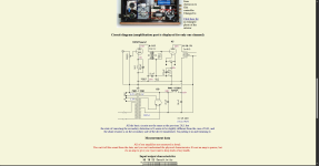
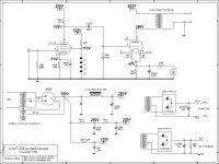
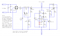
12. A variac or DBT, Dim Bulb Tester, is definitely a good idea if you build any kits and especially so as the $$$ and power go up. I have been resisting getting a variac and have some older incandescent bulbs, new ones are available as "Appliance" bulbs. There are some posts re. DBTs including 1 that I just built, including diagrams.

13. Wire strippers are a necessity, I use Klein 1009, a quality tool that will last a lifetime. Take note that it is etched with "Stranded" and "Solid" which are different notches for the same gauge of solid or stranded wire. For finer gauge I have an old Greenlee that strips as fine as 26 gauge, the current version, 1917SS, is a bit pricey but looks nice.

Many of the projects include pretty much everything that 1 needs to complete a build, but having chachka on hand can make a build easier and more professional looking. Some have already been mentioned in Tools, so I'll skip them with the exception of a second mention of the Ferrule Crimp Kit, I just like that word, Ferrule hehehe!

Chachka AKA Stuff:

1. An assortment of both insulated and "sleeved" spade connectors, see Tnisesm, is worth having. It has appropriately sized female spades for just about any situation that you will run into. As a generalization I like to use Spades/Ferrules in power supply sections of my build, I mentioned earlier that I had been taught that mechanical connection first and use solder to seal the joint, perhaps someone w/ more experience might chime in on this?
Something like Mentbery 160 piece male/female spades, is a nice kit.

2. Having an assortment of metric fasteners can come in handy. My collection of metric screws, bolts, washers, nuts etc. has grown a bit, and while they come in little organizers I just ordered some "Crafts" organizers in an attempt to consolidate.

3. It is highly likely that there will be times when you will need additional wiring, based on suggestions by other forum members as well as reviews on Amazon, :radar:, I purchased 16 and 18 gauge silicone insulated wire from BNTECHGO, also, Xinwang 22 Gauge Silicone Wire..

4. Having a Dymo Label Printer can come in handy, especially coupled w/ Heat Shrink Tube Labels.

After using Haisstronica crimper for a while, I am very happy with the quality and results. Love products that meet or exceed expectations, hence my 😍for this site!

High output coincidental / quasi coax 3 way speaker concept

I've been mulling around a concept that sort of came to me of a coax type 3 way system.
It employs an array of 6 x NE180W in V shape formation.
These sit behind an MTM arrangement of 2 x M74A and 1 x T34B mid and tweeter domes.

it uses the V baffle shape behind the mids and tweeter to time align the whole setup.
This may or may not have already been done by someone, but it looks like a valid concept for a monitor style speaker.

Any thoughts or inspiration?

20250522_015154.jpg

Compound (Sziklai) pre

I gathered these few simple two transistor compound preamplifiers. Would like to know if anyone built some like it, how it worked, which are best performing.
Are there web pages dedicated in designing these Sziklai simple circuit with explaining what part does what?
I noticed some sport feedback cap from output, some don't.
Just want to learn some more. Plus i just optimized nice 3 tap loudness volume pot, which reduces signal to some degree, so instead of simple buffer, i could built simple nice pre.

Attachments

  • piezo-preamp-13.png
    piezo-preamp-13.png
    76.6 KB · Views: 327
  • 6307975505bf9dbeecb276bf4f6785fc.jpg
    6307975505bf9dbeecb276bf4f6785fc.jpg
    33.9 KB · Views: 308
  • oYRjrcI.png
    oYRjrcI.png
    23 KB · Views: 341
  • line_preamp (1).jpg
    line_preamp (1).jpg
    56.8 KB · Views: 347
  • Pre-amplifier-with-transistors.jpg
    Pre-amplifier-with-transistors.jpg
    43.7 KB · Views: 347
  • Like
Reactions: lineup

DIY replacement cartridge and stylus for a Beogram 1200

I love vintage gear and I have a Beogram 1200 with a failing stylus suspension. The major drawback with the old Beograms is the B&O proprietary cartridges and stylus, the fact that B&O doesn't support them anymore, that even ridiculously expensive NOS might fail due to aged stylus suspension and the inability to replace the proprietary tonearm, BUT they sure are nice to look at. 🙂

Anyway, I use my Beogram 1200 almost daily so I really want a way to at least replace the stylus, but how to do that when there are no new ones, no one is rebuilding them, nothing else fit the cartridge and you can't replace the tonearm? Build your own replacement cartridge and stylus?

I know it's a crazy endeavor but I started to play with the idea. I'v done some minor changes to some of my vintage gear but I always make sure to save all original parts and also secure a way to reverse any modifications back to stock. How could I getaway with it on a Beogram 1200?

I started to search the net. Surely someone must have made something close to it right? But I came up with nothing, what a surprise! I didn't let that stop me and I am now documenting my effort in case anyone else search for something similar.

First up, what are the constraints? The Beogram 1200 tonearm is pre bent to some 20 degrees. It's a thin aluminum tube, 13 mm outer diameter and 11 mm inner diameter. The original cartridge is 30 mm long including stylus and it weight 7.5 gram.

My first thought was to make an adapter but the pre-bent arm makes it difficult, most cartridges are made to fit a straight arm and it would totally kill it aesthetically. Next thought was to find suitable donor, something that would fit good enough as a starting point.

The 20 degree pre-bent arm got me thinking about the old Ortofon Concorde and that thought led me to the Ortofon OM cartridge. It can be had for a reasonable amount of money with the 5E stylus and it's well supported with replacement styluses. I decided to give it a try and ordered one from Germany.

My plan was to take the Ortofon OM 5E as seen on image 1, take away everything except whats in image 2 and make something like image 3.

Attachments

  • OM5E-1.png
    OM5E-1.png
    495.1 KB · Views: 744
  • OM5E-2.png
    OM5E-2.png
    246.3 KB · Views: 915
  • NewPickup.png
    NewPickup.png
    97 KB · Views: 769

help me choose an amp

I have a Philips Fidelio H2HR, I think 50 Ohm.
The time has come to build an amp, but recently many doubts have arisen reading in this forum. I thought that the famous Cmoy was suitable for me, instead it seems that it is not so. With my old very cheap Sony one day I mounted class A amps with a mosfet. No, I'm sorry, it's not the sound I'm looking for, the highs are too bright, a sound too edgy for my tastes and for my ears that with tinnitus do not digest these frequencies well. Maybe what I'm looking for is not true Hi-Fi? I'm not sure, I like to listen well but it doesn't matter, I don't want to become even more deaf!! Once I asked for the Cmoy with the addition of a buffer but they told me that with the Fidelio it was OVER THE MAX. But the single Cmoy is not really a good amp... I only have a CD player and a computer, I'm not interested in something portable or tiny, nothing commercial, I like DIY. When I was a boy I built a small amp with op amp and bd139-bd140, a schematic taken from a magazine, it sounded exactly like I DON'T want! Instead the best CD player I ever had, the Philips CD960 sounded wonderful, and it only had NE5534, maybe without even the output buffer, but it drove any headphones. Basically a 40 year old Cmoy! Ok, I'm afraid I've tired you... what do you recommend?
Thank you all!!

MISCO Bold North Audio XBL2 midwoofers look interesting

Looking for a woofer to anchor a 3-way and I stumbled across these: 6501 and 6502. Voice Coil magazine also tested them. I would only use the 6.5" for a center channel, but they have an 8" coming, I was given a very tentative date of June '22. XBL2 motors are known for their very low harmonic distortion in the bass, and these are a good example. But after reading a lot of the Purifi info, I took a closer look at some of the Klippel results like BL flatness and especially symmetry, and Le(x) tilt. These appear to be solving some of the same issues that Purifi identified, like FFM distortion. Now I'm not comparing the two, the usage case different, and Purifi obviously went much further in nailing down the behavior of the driver. But it does seem these are performing very well in the ways that audibly matter vs most other manufacturers. Thoughts?

DAC blind test: NO audible difference whatsoever

(UPDATES BELOW)


That blind test was long due, it's now done.

Started with a 30$ unit (Fiio) against a 3000$ one (Forssell) and once SPL-matched (massive gain difference), no one could tell the difference in a ABX test.

Then, we switched to a different set-up, using a pair of B&W CM9 speakers and the Forssell against a Eximus DP1 (3500$ or so). Same result: impossible to spot them in a ABX.

We were only 4 participants, but regardless it didn't feel like day & night difference to start with... ''Eyes opened'' we FELT differences, but couldn't prove it in the ABX.

Cables, amplifiers, Lossy v.s. Lossless/HD, EQ'd mid drivers, DAC... Nope. Nothing is passing a ABX blind test.

I'm pretty sure, now, that the human auditory capacities are very, very, overestimated. 🙁

The good news is: we can probably save a LOT of money.


-------------------------UPDATE 14th Nov 2017------------------------

Here is some pictures, including the whole room while we change set-ups (the 3rd one is on his way...)

An externally hosted image should be here but it was not working when we last tested it.

An externally hosted image should be here but it was not working when we last tested it.

An externally hosted image should be here but it was not working when we last tested it.

An externally hosted image should be here but it was not working when we last tested it.


-------------------UPDATE 16th Nov 2017-------------------------------


System set-ups #1 & 2 were very useful to spot the possible weaknesses of the whole process and equipement. So today was the Day 1 of the system set-up #3, which includes the following changes, based on observations and also comments and thoughts on this very thread:

.: New DIY speakers including Faital Pro 18FH500 and ribbon tweeters RAAL 140-15D.
.: High quality Solen passive crossover components, including dual Film & Foil capacitors for the tweeters.
.: Instead of iTunes and a computer, we used a Astell & Kern AK300 as the source (Toslink direct line out).
.: No switchbox anymore, a manual switch is made with each pair of RCA cables, in a way the participant cannot know.
.: Larger selection of music to choose from.
.: Shorter AND/OR longer music excerpts duration, whichever makes the participant more comfortable.
.: Uncompressed and also some 24/96 music files.
.: Closer distance to the speakers, from a previous 3,12m to 2,25m.
.: Better SPL-matching, using pure tones and double-checked with 2 differents mic.

Basically, to our actual knowledge, everything was carefully made to optimize the chances of a positive identification in that 3rd and final attempt. That test will continue to run for few days, we welcome participants from DIYaudio. Here are the first results:

3rd set-up - DAY 1

First participant was there last sunday (set-ups #1 & 2) and, sighted, was optimistic about his chances. Felt confident that changes made was for the best. FAILED to identify on every music excerpts.

Second participant, non-audiophile, male 34yo, and did not participate previous rounds. FAILED to identify on every music excerpts.

Comments collected afterwards was unanimous: even sighted, the potential audible differences were extremely thin. They both felt they could grasp some hints, but they didn't made it, through the test. They were the most confident with the 24/96 music file Angel of Harlem from The Persuasions and the 16/44 Ungear Moi from CoH, but it didn't change the results whatsoever compared to other music files.

Conclusions of Day 1: From a very promising 3rd set-up, the hopes are now getting extremely low to find a participant who will be able to spot the 19,99$ DAC from the 3000$ one. We already know that 100% of the population is now an impossible target, we do hope that in the next days we'll find new participants that will get better results.


3rd set-up - DAY 2

3rd participant, non-audiophile, male 35yo, and did not participate previous rounds. FAILED to identify on every music excerpts.

4th participant, audiophile background, female 42yo, and did not participate previous rounds. FAILED to identify on every music excerpts.

5th participant, non-audiophile, male 45yo, and did not participate previous rounds. FAILED to identify on every music excerpts.

6th participant, non-audiophile, female 40yo, and did not participate previous rounds. FAILED to identify on every music excerpts.

7th participant, audiophile +DIY background, male 40yo, just passed audiogram (8dBHL, symmetric). FAILED to identify on every music excerpts.
  • Like
Reactions: Miller-8

Looking for help with the volume of my box

Can someone help me out with the volume of it. Thinking of putting my x-12 in it for a minute if the numbers are close enough
29,5 depth (tall) x15x15
The front for the sub is recessed from the top 2.5 “
The ports are 3.5-3.5-4.5 triangles and they are 23.5 “ deep and there are 4 of them
The face where the sub fits is 2.3/4 from the top .
Everything is 3/4.”
Any thoughts? Ideas? Anyone know who made this? It is very heavy

Attachments

  • IMG_3579.jpeg
    IMG_3579.jpeg
    946.1 KB · Views: 10
  • IMG_3577.png
    IMG_3577.png
    2.8 MB · Views: 6

Rotel transformer Help

i have a rotel power amp the mains transformer blew
i have a transformer of the correct voltage but only one output 40-0-40 the original had 2x 40-0-40 one for each amp board
the amp is bridgeable
what i would like to know is can i feed both amp boards which have on board rectifiers before the smoothing caps with just one output
or should i remove the rectifiers from each board and just use one to feed both boards schematic included
many thanks Glenn
1749128525805.png

1749128806730.jpeg


1749128955531.jpeg

1749129151848.jpeg

Attachments

  • 1749129076861.jpeg
    1749129076861.jpeg
    397 KB · Views: 51

Plethora of Pinjatas / SET P amp(s)

Finally, Plethora of Pinjatas, origin of P series of amps

These (P) being more or less derivatives of my recent M2 derivatives ........and you know them , so no need to go in detail

So, active FE instead of buffer+autoformer FE; biasing mech. being more or less same (current sense in rails), only - with help of current mirrors, being sorta flipped upside down, vs. previous optocoupler based one

even if optocoupler based biasing is more than good, believe me, this one is even better ...... in anything you can remember to ask about

Iq and Offset stability is bespoke, in any domain I can think of - time, temperature, rails change ( mains fluctuation), no even slightest pops during Power On and Power Off

everything to embrace Square Law OS :clown:

(aha, this one being origin, even if its bigger brother - Babelfish XA252 been made first)

OK, straight MOS being real Plethora of Pinjatas ....... (is it Mini Babelfish XA252?)

SET P being then same pcb with twist - upper mosfet in Schade arrangement (is it Mini Babelfish XA252 SET ?)

pretty close to point where I can't even follow my self, go figure :rofl:

'nuff babbling, some usual pics

schm is cumulative; down will post separate ones

Attachments

  • Plethora of Pinjatas_SET P Eagle sshot.png
    Plethora of Pinjatas_SET P Eagle sshot.png
    56.6 KB · Views: 1,882
  • Plethora of Pinjatas_SET P top render.png
    Plethora of Pinjatas_SET P top render.png
    121.4 KB · Views: 759
  • Plethora of Pinjatas_SET P bottom render.png
    Plethora of Pinjatas_SET P bottom render.png
    69.3 KB · Views: 1,868
  • Plethora of Pinjatas_SET P all parts sch.png
    Plethora of Pinjatas_SET P all parts sch.png
    203.8 KB · Views: 1,991

8" high efficiency midbass driver suggestions

I'm in search of a decent 8" midbass driver. Needs to do mid-90s dB/2.83v and handle the 300 - 900 hz range with ease, preferably 4 ohm impedance.

The main issue I'm running into looking for a suitable driver is sufficient xmax along with efficiency. The driver will need to handle some decent power without turning into mush with loud transients. Obviously it will need to be some sort of pro audio driver given the application. Low distortion is a must.

Drivers like the Audax PR170MO don't have enough xmax to play louder without using steeper HP filter slopes. Levels I expect are 110 dB peaks in the specified range.

My other favorite B&C 8NDL51 isn't quite efficient enough and isn't available in 4 ohms. The 8PS21 has the same issue.

The 8PE21 is efficient enough as an 8 ohm driver, but not enough xmax to deal with a 300 hz 2nd order HP at higher output levels.

I've toyed around with the idea of using 2 drivers, but this will result in weird vertical dispersion issues.

Any suggestions?
  • Like
Reactions: Frisch Feld

Salas SSLV1.3 UltraBiB shunt regulator

As the beloved SSLV1.1 BiB shunt reg was getting long in the tooth, especially for NOS JFETS, I had in mind for some time now to design its successor. The goals were: 1. In production parts 2. Much simpler to set up. 3. Better technical and subjective performance.

After many breadboard experiments and two prototype PCB iterations I feel that my goals were finally met. So here comes the UltraBiB V1.3 😀

-Uses no NOS parts.
-Can do 5V to 40V output without changing a thing in its parts configuration.
-Nothing to choose and match. No tolerances in predicting its CCS limit setting.
-Has 45dB more open loop gain and many times less output impedance than 1.1
-Sounds easily better.
-Its an electrically and mechanically drop in replacement for an upgrade from 1.1

I have already given spare earlier proto boards with now deleted experimental features to few local beta testers. They are all happy by now as far as I know. The pictured board in green is the final layout in just cheapo proto that's a pain to rework and its pads vaporize in the end. It will come in proper grade black solder mask and immersion gold three sections board just like the original.

Attached: Zout plot for 150ma spare current and noise plots for 100,150,220,330,470,1000uF C2 (red 220uF). Also the rails probed on the scope for positive and negative sections. Here are typical values schematics also. I will write a PDF with instructions. Not that there is something truly special to consider when building it with the suggested parts but to describe it better as an item and to clarify details and precautions.

Updates:
31/5/18 R9's value update
1/6/18 OL sim at 100mA spare
2/6/18 Build Guide PDF added (0V0b)
24/5/19 Triplet board dimensions picture
21/6/19 The PF5102 JFET became EOL. But GB long term supply is secure. For substituting with J113 see info in post #1559
15/5/20 BC560C became EOL. But Group Buy long term supply is secure. BC559 can be used up to 30V output. BC556 for 31V-45V output.
2/7/23 LNA instrumentation measured a very low 2nVrtHz spectral noise density from the UltraBiB under real working conditions. post#3,688

Attachments

  • UltraBiB.jpg
    UltraBiB.jpg
    498.4 KB · Views: 27,172
  • UBZo150mSpare.png
    UBZo150mSpare.png
    14.4 KB · Views: 25,790
  • UBNzC2100-1000.png
    UBNzC2100-1000.png
    15.8 KB · Views: 23,521
  • PSU noise 1us 2mV.png
    PSU noise 1us 2mV.png
    32.3 KB · Views: 25,457
  • UltraBiB-Pos.png
    UltraBiB-Pos.png
    36.3 KB · Views: 27,831
  • UltraBiB-Neg.png
    UltraBiB-Neg.png
    27.2 KB · Views: 17,059
  • OL470R9100mSPR.png
    OL470R9100mSPR.png
    26.2 KB · Views: 12,878
  • UltraBiB_Build_Guide_0V0b.pdf
    UltraBiB_Build_Guide_0V0b.pdf
    556 KB · Views: 11,713
  • UBiB_Triplet_Dimensions.png
    UBiB_Triplet_Dimensions.png
    30.6 KB · Views: 8,871

Cubo Home

To honour reaching 1K subscribers on my Youtube channel, I'm releasing the plans for Cubo Home. It's an optimisation of it's predecessor, that was designed to have the sound and low frequency response of Cubo Sub in a small format Home or Car sub. Cubo Home is great for above average levels of sub bass, with just about any sub amplifier. As a day-to-day go-to sub, whether for music, gaming, movies or to entertain a small flock of friends or family.

If you could only have one sub, build Cubo Home. If you can have three subs, build two Cubo Home and one Cubo Infra.

Just like its cousin Cubo Infra, it can be used in front-firing and down-firing mode. In a down-firing position the chamber/ cavity/ port in front of the driver reduces in-band THD, for a cleaner and deeper sounding bass, this is especially helpful with low Mms (i.e. older or PA-mid-bass) drivers.

It works with a very wide range of 12" drivers, even those that weren't designed for sub bass performance. Designed for all 12” PA mid-bass or bass drivers, to atain an usable frequency response down to 30-ish Hz*. Tested with drivers such as the 18 Sound 12W700, 12ND930, 12NLW9300, the Precision Devices 12SB30 and the Eminence Delta 12LF. Other suitable drivers that come to mind are The Box 12-280/8-A, 12-280/8-W and the Dayton Audio PA310-8. Cubo Home is also suitable for 12” home audio and many car audio drivers. It will even work with 10" drivers, especially those geared towards high excursion capabilities. If you're unsure a driver is suited, e-mail me at questionsaboutcubo@gmail.com

* To maximize low frequency performance, loosely fill the rear chamber with fibers, such as Polyfill/ Fiberfill, without blocking the airflow to the driver and port.

Size: 40 x 40 x 40 cm (Metric), 16 x 16 x 16 inch (Imperial in the making)
Frequency: From 30 Hz up to 100 Hz
Enclosure Type: Reflex/ 6th Order Series Bandpass

Metric Construction: Cut from half a sheet of 15 mm MDF (122 cm x 122 cm), no angled cuts.
Imperial Construction: Cut from half a sheet of 5/8" MDF (4' x 4'), no angled cuts.

Front-firing:
1 Cubo Home.png


Down-firing:
2 Cubo Home.png


Bracing/ detail:
3 Cubo Home.png


Metric Construction Plan:
4 Cubo Home Construction Plan.png


Metric Cut Sheet:
5 Cubo Home Cut Sheet.png

Ambitious direct bias PSE 300B with dual PSUs

It's been 3 or 4 years since this newbie started learning tubes from the wealth of knowledge here. In that time I've been collecting schematics, studying, experimenting, buying parts and tubes that mostly just sit, fun to me but weird to my wife. A few months ago I fell into starting something ambitious, figuring out how I would go about building a direct bias 300B PSE amp with dual PSU's. Inspired by Andrea Ciuffoli, because I kept coming back to his 300B PSE schematic over time. I began with his schematic and dumped every thought I'd need to remember about making one myself onto paper. Simultaneously I've wanted to make dual "boat anchor" PSU's for it, inspired by the Border Patrol amp I really liked at AXPONA. The intention is for the boat anchors to have variable B+, umbilical connected to the amp, so I can re-use the PSU's maybe for a second project. So I'm imitating Andrea Ciuffoli and Border Patrol here but learning. I've attached the schematic as of today, if anyone wants to comment, recommend, help, find errors, etc. Along with the electronics, I'm also doing the mechanical design in 3D CAD as I hope to machine and fabricate the chassis all myself as well. As that gets farther along I'll post 3D models too. Thanks!

Last schematic update: See most recent "last update" post from me.

Other relevant links for this build:

Making the umbilical:
https://www.diyaudio.com/community/...age-umbilical-aircraft-inter-connects.421545/

Recovery time in a PSU calculations:
https://a-direct-heating-triode.blogspot.com/2018/06/lcr-phono-preamp-part-3.html

Attachments

The Wolverine 5th Group buy

Hi Guys,

Please register your details for the Wolverine 5th Group Buy - Pre Order.​

After the success of the past four group buys and increasing demand for Wolverine boards, we are thrilled to announce another group buy for the DiyAudio community.

1741778325551.png

This time, we are offering the new and improved Wolverine V5 boards, along with supporting parts and boards:

The IPS, EF3-3, EF3-4 and EF3-5 boards will now include mirrored versions for Left and Right channels! These allow inputs at the rear of your chassis and outputs on the lower heatsink half, all while fitting the current UMS (with just 3 new holes for EF3-4, courtesy of Gianluca’s updated drill pattern). Huge thanks to Mainframe and DanielJW for prototyping, Harry for BOM review, and Jeremy for schematic checks.
  1. IPS, Pre-Driver & Driver Heatsinks with Mill-Max pins installed:
    • EF3-3 (IPS, Pre-Driver & Driver)(Amp Board,Parallel or Perpendicular Mount to Main Heatsink): $27.50 USD (6 Heatsinks Total)
    • EF3-4 or EF3-5 (IPS & Pre-Driver)(Amp Board, Parallel Mount to Main Heatsink): $22.50 USD (4 Heatsinks Total)
    • EF3-4 (IPS, Pre-Driver & Driver)(Amp Board, Perpendicular Mount to Main Heatsink): $27.50 USD (6 Heatsinks Total)
    • IPS: $10.00 USD (2 Heatsinks Total)
1741777513778.png
  1. 2SA1381E / 2SC3503E Transistors:
    • $6.00 USD per pair.
1741777528509.png

We are also offering the following supporting boards:
1. "Dual Bridge Rectifier Board" by @stuartmp – Includes Schematic & BOM:​
- Two boards are required if you plan to build a dual mono design.​
- $12.50 USD each.​

1741777559436.png

2."Speaker Protection Board" by @jjs – Includes Schematic & BOM:​
- One board is for one Channel.​
- $20.00 USD per pair.​

1741777581389.png

3. "T-Ground Board" by @stuartmp – Includes BOM:​
- Two boards are required if you plan to build a dual mono design.​
- $5.00 USD each.​

1741777602572.png
4. "Ground Lift" by @stuartmp – Includes insulated washer & BOM:​
- Two boards are required if you plan to build a dual mono design.​
- $5.00 USD each.​

1741777619037.png

Thank you all for your support of the Wolverine project over the past 3 years. It’s incredible to think our first group buy was back in March 2022.

Registration Instructions:
We will follow the same process as the 3rd & 4th group buys to streamline processing. Board color will be determined based on order numbers; if insufficient, only one color will be ordered.

Pricing for Boards:
Wolverine V5 Special Edition IPS Board
(2 boards) (Right and Left channel):
$15.00 USD.​
(Color to be determined: possibly yellow with blue silkscreen please give us your feedback on the forum)​

1741778147567.png


1745289904304.jpeg


EF3-3 Boards: (270mm x 77mm)
2 x Precision EF3-3 (V5.0) Boards (Left and Right channel) + 2 IPS Boards: $50.00 USD.​
4 x Precision EF3-3 (V5.0) Boards (Left and Right channel) + 4 IPS Boards: $90.00 USD *.​
1745289557436.jpeg


EF3-4 Boards: (347mm x 77mm)
2 x Precision EF3-4 (V5.0) Boards (Right and Left channel) + 2 IPS Boards: $55.00 USD.​
4 x Precision EF3-4 (V5.0) Boards (Right and Left channel) + 4 IPS Boards: $95.00 USD *.​
1745289594700.jpeg


EF3-5 Boards: (354mm x 77mm)
2 x Precision EF3-5 (V5.0) Boards (Right and Left channel) + 2 IPS Boards: $57.5 USD.​
4 x Precision EF3-5 (V5.0) Boards (Right and Left channel) + 4 IPS Boards: $100 USD *.​
1745289622732.jpeg
I’m excited to share a fresh development for the Wolverine family: the EF3-5 output stage board! As you know, our current lineup includes the EF3-3 (3 current gain stages, 3 output transistor pairs) and the EF3-4 (3 current gain stages, 4 output pairs).

Now, we’re taking it up a notch with the EF3-5, featuring 3 current gain stages and 5 output transistor pairs for even greater power and stability.

To top it off, I’ve mirrored the EF3-5 design—just like the EF3-3 and EF3-4 in the 5th Group Buy—offering dedicated Left and Right channel versions. This keeps the inputs at the rear and outputs low on the heatsink, maintaining that clean, symmetrical layout you’ve come to love.

The EF3-5 boards are 7 mm longer and 10 mm wider than the current EF3-4 boards. All the holes still follow the UMS, except for the two at the top where the output transistors mount—they’ve moved up 10 mm. The output transistor mounting holes have also shifted up 10 mm, so some drilling and tapping will be required if you’d like to use the EF3-5.

The EF3-5 is perfect for those pushing higher currents or lower impedance's (think 2-ohm loads or beyond) with the same Wolverine Class AB finesse.


Please note.
The discount will only be applied for those members who order boards before they are ordered from the PCB Manufacturer.
If you wish to order more than 2 sets or adjust quantity, please contact us for pricing details.


Shipping: Prices exclude shipping costs. Shipping is at cost price plus $3.00 for packaging. No added handling fees. A copy of the shipping receipt will be emailed upon payment.

Each Order Includes:
  1. Your ordered PCBs.
  2. A3 Schematic copies for 57V and 64V versions. (Dropbox Link)
  3. The Build Guide (~135-page illustrated A4 document). (Dropbox Link)
  4. BOM in Excel with Mouser part numbers. (Dropbox Link)
  5. Heatsink Hole Pattern DXF & PDF files. (Dropbox Link)
  6. "How to Wire an Audio Amplifier" by Bonsai. (Dropbox Link)
  7. Future updates will be available via Dropbox. Please provide an email for this purpose.
Payment: Through PayPal. Requests will be sent upon ready-to-ship boards.

How to Register:
  1. Open the attached Excel order sheet, fill it out, and email it to: Stuartmp@internode.on.net
    • Subject: "Wolverine Project – Your DiyAudio Username"
  2. If unable to open the file, please reply with:
    • Total number/type of EF3-3, EF3-4 & EF3-5 boards.
    • Name and total number of any of the supporting parts / boards on offer.
    • Full name, address (including country and postcode).
    • Phone number for tracking.
    • Your PayPal email address.
    • You Email address for Dropbox updates.
We will order boards once a sufficient number of pre-orders are reached and keep you updated throughout the process. Once received, we will calculate shipping and send payment requests. You will receive a tracking number once your order ships.

Please refrain from using my email for other inquiries; post questions on the main Wolverine Build thread or contact me via DiyAudio PM for order-related questions.

Wolverine Development Thread
For ongoing project updates and technical discussions, visit the Wolverine Development Thread on the DiyAudio forum. Engage with fellow audio enthusiasts and share your build experiences.

Wolverine Build Thread

The Wolverine Build Thread is your go-to resource for assistance with assembly tips and troubleshooting advice. Feel free to ask questions and contribute your insights.

YouTube Build Series
Explore our YouTube Build Series for visual guidance on assembling your Wolverine amplifier. Our instructional videos cover each step-in detail, ensuring a smooth build process. Thank you to @danieljw for putting this series together.

Support Contacts
Feel free to reach out to me directly through the forum's messaging system or my e-mail if you have any question related to the ordering process.

We truly value your involvement in the Wolverine project. By working together, we continue to make high-quality audio amplifiers accessible to enthusiasts worldwide. Thank you for your enthusiasm and support.

Best regards,
Stuart & the Wolverine Team

Attachments

3-way to active - Hypex FA253 - learning project

Hello, All!
Just joined today as I found a very useful guide here on using Hypex Filter Design, thanks to DannerD3H.

I have always been a music and audio fan and find acoustics and speakers particularly fascinating. I always wanted to design and build my own speakers but never got to it, mainly due to lack of space to use for woodworking (I live in a small flat). But still decided to go for it. I will work around the difficulties somehow. If there is a will, there is a way.

I have reasonable understanding of audio, electronics and design process and ok to use my hands, but I have almost no experience, so face a steep learning curve.

First thing I did is buy the Loudspeaker Design Cookbook. Reading it now. Learning curve.

I have a pair of old slim floorstaders (description to follow) that I intend to convert to actives. This will help to initially avoid much woodwork, while still learning about drivers, crossovers and amps and box interaction. This will be done in two steps:

Step 1 - add Hypex Fusion amp and use existing drivers and enclosure as is

Step 2 - replace the drivers for better specced ones, modify the box

This will hopefully take me to a future point of fully building larger speakers and maybe a sub. One day.

So far I have bought a Dayton UMM6 mic, a Fosi V3 amp and just about managed a few measurements in REW of the speakers in passive form and of individual drivers. I managed to install on old version of HFD software on an old Win XP (!) laptop and hope to use that to program the FA253s when they arrive later this week.

I do stumble a lot and have lots of questions and definitely need some help. I will be asking here and would appreciate any help from the more experienced members.

I will make a post with the existing speaker details and maybe a few other things I am struggling with.

FWIW I do have some forum history on a couple of HiFi forums: Hifiwigwam and Audiosciencereview.

So, wish me luck.

Active 3-way Hypex FA503 or FA253 (with future sub(s))

Early thinking over the next (future) project - some sketches:

Driver starting point is:
Tweeter: SB26WG or Seas DXT (both with waveguides). The SB I am familiar and happy with. The Seas seems well reviewed/measured and has a similar WG.
Mid: 12cm seems to blend with tweeters much better than 15cm, so likely stick with this size. ScanSpeak, either the Revelator or the Illuminator in 12cm 4Ohm
Woofers: thinking 22-28cm, e.g. Scanspeak Revelators 22cm or 28cm in 4Ohm.

DSP/Amp: Hypex FA503 or 253 (subject to power needs per WinISD simulation).

A single or dual sub will be added in future, 15in or 18in.

Cabinet proportions roughly per sketch, subject to box sim. Width a few cm larger that the woofer. Beveled front panel about 4cm. Either symmetrical or asymmetrical to further smooth out diffraction ripple. Indicator/IR sensor at front.

Prelim crossovers 200/250Hz and 2-3kHz.

1750344156040.png
1750344222287.png


1750344380913.png
  • Like
Reactions: Juhazi and eddantes

Help Diagnosing Headphone Output Issue – Marantz HD-DAC1 (CUP12689 Board Suspected)

Hi all,
I’m working on a Marantz HD-DAC1 that has two persistent issues with its headphone output:
  1. Colder, flatter sound with noticeably less volume and body (3 to 4 decibels less) compared to a second, identical unit I own.
  2. Audible static/hiss at 100% volume with no signal playing — not present on my other unit.
I connected both Marantz put both volumes knobs all the way to 0, then used one of the remotes to increase the volume to 25% (Both volume controls went up together) which clearly let me hear the difference in volume.

What I’ve done so far, taking boards from my good unit:
  • Swapped the DAC board (CUP12688Z)
  • Swapped the power supply board (CUP12689-2)
  • Swapped the headphone amp/bias board (CUP12689-3)
  • Swapped the front panel and logic boards (CUP12687-2 and COP126878)
  • Swapped the transformer (CLT5P055ZE)
None of these fixed the issue. The only original part remaining is the mainboard (CUP12689).

Headphone used is a Beyerdynamic DT1770.

I believe only the headphone output is affected, when connected through RCA output they sound identical.
  • I did replace C958 and C968, but didn't make a difference.
  • Bias is set correctly and matched between channels
Any help tracing the signal or suggesting next test points would be greatly appreciated!
Photos available on request.

This is the service manual i'm using -> Marantz HD-DAC1 Service manual

Thanks!
20250414_031112.jpg


20250414_031131.jpg

BK Electronics mosFET 100 watt modules

Hi Guys
New on here. Just bit of advice as I don't know much about builds of op amps. I got this pair which are in pretty good nick and have used a good old spare chassis I had lying around to mount these in.

Now am I right that the heat sinks don't need earthing. I've earthed the j50 and k135s all powered up okay and I'm getting 47.5v on main rails. Not measured anything else yet just letting them burn in for a bit.

I now need to mount the pots which I think are 47k? And obviously put in the output input XLR sockets in. I have a spare set of old led lights for the on off switch but was wondering if I could run them from the vu meter points +12v put in a shunt resistor to get voltages down. Not sure what rating they are? Need to work that out.

I also have a decent fan but it's 115vac so need to work out how to get that working as I also have a pair of heat sensors you mount onto the heatsinks so think I'mgonna need to build a module to get that working with right voltage rating or just buy a 240v fan. But I'd rather use what I have if possible. So quite a bit to do yet. But I'd like to get it right and not blow it up.

When I got these they where mounted in a homemade chassis but it was a mess and everything in there apart from the modules had all been sprayed black including the wiring. The pots where covered in gather tape and on switch on you could not turn the volume down it was like it was just set at a level. You could increase volume. So is this normal or was it wired up wrong? Again wires connected together using a bit of solder and insulation tape. Hence moved into a decent chassis.

Anyhow any feedback welcome.

Cheers

Best tube amp for Acoustat 1+1

I bought my brother a restored pair of these amazing speakers. His local high-end guy convinced him to pair them with transistor amps because of their power requirements. However, his system now decidedly lacks fluidity and musicality and has a clinical, almost digital sound. When I fell in love with the 1+1s, I was driving them with an Audio Research D70. They sounded heavenly (at low levels). We only listen to classical and old jazz. Is there any tube amp that you can recommend with these?

Thank you, and happy holidays!

Seeking recommendations regarding speaker enclosure for field coil driver

Hello everyone

I have recently been in contact with Mr. Rullit regarding his exceptional field-coil drivers, and I intend to place an order for the nine-inch “Super Aero” model in the near future. At present, I am in the process of researching which type of speaker enclosure would best complement these drivers. However, I must note that my options are somewhat limited due to certain non-negotiable constraints—most notably, I am unable to accommodate large horn systems.

To provide some context: I reside in a historic manor apartment, where my dedicated listening room measures approximately 25 square meters (5 × 5 meters), with ceilings reaching a height of 2.7 meters. My musical preferences primarily include classical and jazz repertoire, ranging from solo performances to chamber ensembles and full orchestral works. As an amateur pianist, I place a high value on natural sound reproduction—one that conveys holographic depth, dimensionality, and body, while offering a rich and organically pure tonal character. From my impressions, Rullit’s drivers seem to embody these qualities remarkably well, particularly in terms of transient speed and natural timbre. The sound is airy but has body, it is transparent but has character, it is neutral but has depth. In order words it has the emotional realism that I strive for.

As mentioned in my introductory post, I am quite new to DIY audio projects. However, I have allied with skilled people —one of whom has experience with CNC machining, and another who excels in veneering speaker cabinets with real wood finishes.

From my conversations with knowledgeable individuals, it appears that Rullit drivers are well-suited to a variety of enclosure types, including dipole, front-loaded horn, open baffle, and resonant designs. Personally, I am inclined toward dipole or resonant enclosures, primarily due to their more manageable size. Unfortunately, I believe my room is too small to accommodate horn systems effectively, and open baffle designs would require substantial space behind the speakers, which is impractical given my current interior layout. I have attached photos of possible solutions.

I would be most grateful for guidance and recommendations that could assist me as I move forward with this project. Even specific design plans would be perfect! Any reflections, suggestions, or insights would be sincerely appreciated.

Thank you very much for your time and considerations

Attachments

  • Skærmbillede 2025-06-05 kl. 18.59.23.png
    Skærmbillede 2025-06-05 kl. 18.59.23.png
    532.7 KB · Views: 136
  • Skærmbillede 2025-06-05 kl. 18.59.49.png
    Skærmbillede 2025-06-05 kl. 18.59.49.png
    806.6 KB · Views: 133

Can anyone Identify this amp? LP! FR200

Looking for some help trying to identify this amplifier. Not sure of the brand. LP! ???? there are no other identifiers on the amp anywhere. I have googled my brains out and came up with nothing. Anyone familiar?? anyone seen this brand before??

The customer is absolutely in love with it and wants it repaired. trying to figure out what in the heck it is.

Attachments

  • 20250620_115408.jpg
    20250620_115408.jpg
    542.7 KB · Views: 119
  • 20250620_115413.jpg
    20250620_115413.jpg
    298.1 KB · Views: 139
  • 20250620_115441.jpg
    20250620_115441.jpg
    942.8 KB · Views: 139
  • 20250620_115456.jpg
    20250620_115456.jpg
    510 KB · Views: 137

Gain problem with MARANTZ PM7000

I am working on a Marantz PM7000 with many issues, most of them are already solved. But I have a problem that it is literally driving me nuts. One of the amp channel, RIGHT CHANNEL, has a very low gain.
I first focused on the input differential amp, prior to measure, I checked transistors and fixed many cold soldering. The problem remained and I began to do some measures. As I have the other channel working I did, as usual, some comparative readings and on DC I can't find any difference from the good one to the failing other. Applying a 1 Khz signal I see the signal reaching R3316 and R3314 is very low if we compare it to the 3315 and 3313 on the Left Channel. And I am a bit lost, this are the challenges I like but, at this point, I think I need some fresh ideas as mines are on a loop. I have tested voltages, as mentioned, transistors (not with a cheap transistor tester but with a wonderful LEADER LTC-906A and a modern PEAK DCA75), diodes and resistors, even some capacitors that, to my surprise, were encapsulated as a resistor. First time I see this. The feedback is OK, power supply and limiting-protection resistors, everything is just fine.
Also, I didn't say it earlier, the signal reaching both channel inputs has the same level. I want to say this in case some may think I have any issues on tone or volume control, this is already fixed (there were some problems before)
I look forward for your experience and ideas because mine are exhausted. Thanks in advance

Attachments

  • PM-7000 MAIN AMPLIFIER SCH.jpg
    PM-7000 MAIN AMPLIFIER SCH.jpg
    173.2 KB · Views: 69
Projects by fanatics, for fanatics
Get answers and advice for everyone wanting to learn the art of audio.
Join the Community
508,332
Members
7,913,706
Messages

Filter

Forum Statistics

Threads
407,479
Messages
7,913,706
Members
508,332
Latest member
alanlin1