You are using an out of date browser. It may not display this or other websites correctly.
You should upgrade or use an alternative browser.
You should upgrade or use an alternative browser.
Filters
Show only:
150.4 starting problem
Hello diyaudio family, the problem of the device is that when the plus and minus are connected, the LED light turns red, there is no reaction when the remote is connected, there is no defective part around the TL494, can you help?
Attachments

45 tube grid leak resistor
- By Rob7
- Tubes / Valves
- 2 Replies
45 tube driven by 6SN7. .1 uF coupling capacitor. Does a 220K grid leak resistor seem reasonable? Should I go higher?
Active RIAA component calculator for tube prephono
- By TasoTaso
- Analogue Source
- 22 Replies
Hi, there is an "automatic" calculator on the internet to calculate the value of components for the RIAA in a prephono scheme like the ear834 (the RIAA ring includes the tube v2 and v3) and like the Marantz 7 or Audioresearch sp3/6/8 (RIAA ring includes all 3 tubes)? Many thanks 🙂
Help with building my first Amp
Hello all: I just registered here, so this is my first post.
I have been debating between buying a Buckeye or VTV class D Hypex Amp. Cost is $1100.
I got to thinking wouldn't it be cool to build my own amp. Unsure if its even possible or what the cost would be.
I want to power my front stage LCR (Emotiva C2+ & Revel Concerta2 F36)
My requirements for the system are 500w x3 channels and a RCA/Banana Plug connectors.
I figure I probably would not even save that much money, but it would be a cool experience.
Can anyone point me in the right direction on where to look, and how to get started?
I have 0 experience with electronics like this. Most experience I have is installing speakers and a head unit in my car. My ONLY soldering experience is soldering a loose speaker wire back onto the speaker chassis.
Would building a 3 channel amp with 250wpc or 500wpc be too much of a undertaking for somebody new?
I am debating between Hypex vs Purifi as well.
Any help you all could provide would be greatly appreciated.
(Side note: What is this forums thoughts on the Texas Instrument Power supplies, being used by Fosi and AIYIMA. Such as the Fosi V3 Mono)
________________________________________________________________________
Edit:
After using the search bar it appears that a kit would be easier.
Apparently " Class D amps use SMD chips" which are not for a beginner.
Any help just pointing me in the right direction would be great !!
Free book: Horowitz and Hill, The Art of Electronics
A very well respected book. Just pay for shipping.


FYI - Avalon DIY Dayton Audio drivers, Maybelle Audio Vietnam
FYI-

Google Translate
https://translate.google.com/
Drivers: Dayton Audio RST28F-4, RS52FN-8, RS270-8
https://linhkienloadai.vn/products/loa-davalon-boi-maybelle-audio
https://linhkienloadai-vn.translate...uto&_x_tr_tl=en&_x_tr_hl=en-US&_x_tr_pto=wapp
https://linhkienloadai.vn/collections/mau-thung-1
Crossover @ 10:30-11:00 first video
https://maybelle.com.vn/diy-loa-ava...-su-dung-cu-loa-cua-dayton-audio-nd80938.html
Crossover. Cabinet?
Speaker Enclosures for Neo8 Planar Drivers
- By WA Baker
- Planars & Exotics
- 0 Replies
This must be an FAQ, but I did search this forum for related threads and came up empty. Are there off-the-shelf speaker enclosures routed to mount the 8" Neo-8 drivers? Same dimensions as the GRS 8" planar drivers that Parts Express sells now. I've been running mine using temporary enclosures for far too long, and post-COVID I no longer have access to a shop where I could do the routing myself.
My question is somewhat counter to the DIY ethic, but I love these drivers and would like to finally get them properly mounted.
My question is somewhat counter to the DIY ethic, but I love these drivers and would like to finally get them properly mounted.
FaitalPro HF146R 8ohm
- By HomeMadeSin
- Swap Meet
- 0 Replies
SOLD
I have a pair of like new, maybe 5 minutes on one FaitalPro HF146R compression drivers, with original boxes (will send / add pics later). $400 for the pair shipped to the lower 48. Also have a pair of LTH142 horns as well - +$100
I have a pair of like new, maybe 5 minutes on one FaitalPro HF146R compression drivers, with original boxes (will send / add pics later). $400 for the pair shipped to the lower 48. Also have a pair of LTH142 horns as well - +$100
MOST Bus as a house bus
- By Rhys_m
- Everything Else
- 0 Replies
Really unsure of the best place to put this, but really wanted to document it in case it actually works well!
I've been doing a huge amount of work over the last 18 months or so to try and open up the MOST bus audio system that can be found in cars, eventually creating a MOST bus HAT for a Pi. I am now onto an STM32 based board that will act as a sound card for transmitting audio and control messages.
For a long long time I have been tempted by some multi room audio, and ever since I have been play with the MOST stuff I have been thinking how well it could work with that.
For people that don't know a huge amount about the system, here's a quick overview of it (forgive any numbers being wrong, this is all off the dome!)
MOST is a fibre optic network that has a network master. The network master sets the Fs of the network, either 44.1khz or 48khz. It transmits upto 15 quadlets of synchronous data at once, so allows up to 15 16bit 2 channels streams all at once. A device can stream audio onto the network after negotiation with the master, and any device can retrieve that audio off of the network aswell by setting those quadlets to be assigned to it's own sink.
So here's my thinking of how I can have a play with this.
I've managed to source 10metres of the correct plastic fibre optic cable from ali express for £14, I am going to put a MOST device into everywhere that currently has some type of amplifier (man cave, living room, garage, kitchen), I'm then going to route the cable into each room and build some kind of web app to control the system. So if I am playing audio on my Mac, I will stream that onto 4 channels, if I want that audio picked up in the living room, connect that device to those 4 channels etc etc.
Now I know someone will raise the question and yes I know this is a lot of effort for something that can be done wirelessly these days, but I have a bunch of spare devices that work perfectly well from prototyping etc, also I've grown rather attached to the system, and most importantly - it's going to be great fun!
Anyhow, that's the current thinking, I am happy to keep this post updated if people find it of interest!
Monster Power HTS 5100MKII Anormal Voltage, Help Please!
- By Mayrel2015
- Power Supplies
- 0 Replies
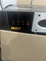
Greetings to all, I would like you to help me solve this problem, I have this Monster POWER that was working perfectly, I went to adjust the front brightness to stronger because it was very dim and when I increased the intensity, the Monster Power turned off, it starts to the blue CLEAN POWER ON light flashes and after three seconds the red ABNORMAL VOLTAGE light activates, it flashes for about 3 seconds and the CLEAN POWER ON option is activated again, thus remaining in a loop, three seconds in this option, it goes to the other for three seconds, any idea what's happening? Could you help me solve this problem? Thank you for reading.
Attachments
New DIY kit: SEAS Aphel 2 way old school floorstander
For those of us guys, in our best age, who likes old school speakers with large high sensitivity paper midwoofer and wide baffle here it is.
We are goong back to the good old Snell days but with more dynamics and especially details in the treble. The alu dome tweeter sounds indeed good. And you can play loud to.
One of the major benefits with 8 inch and wide baffle is warmer lower midrange and very good punch in the bass. It sounds good with all kind of music.
It is also an easy load for the amp.
Some will comment the power response dip in the crossover area in this and all 8 inch + dome tweeter constructions but to be honest, the sum of advantages will make up for this. And you can barely hear it.
The drivers is as «high end» as you are used to in the HiFi shop, but not expensive though.
Complete drawing and crossover description is here:
https://www.seas.no/index.php?optio...s-aphel-kit&catid=66:seas-diy-kits&Itemid=345
What’s Terrence Howard talking about?
- By Booger weldz
- The Lounge
- 11 Replies
@BP1Fanatic , what is this the dudes thing about freqs and Platonic solid shapes and angles and wavelengths?
Login to view embedded media
Login to view embedded media
120hz hum in one 845 SE monoblock — what am I missing?
- By pjanda1
- Tubes / Valves
- 4 Replies
Hi,
I've got some monster 845 SE amps based on the Grover Gardner circuit. (Parallel 6N7 to triode EL34 to 845, SS rectified CLCLCRC. This isn't my troublesome two chassis stereo version of the same circuit I've posted about in other threads.)
When I got them, one had a low level 120hz hum. After using them for two years, I took them to the bench to replace an intermittent power switch. I got overly excited and replaced all of the power supply capacitors (many, given the series caps), changed the filament supplies changed to Coleman regs with transformers to match, swapped in newer and fancier switches and jacks, tidied up some wiring, etc.
After deploying the parts cannon and bringing them back to life, one amp is still very quiet and the other STILL has a low level 120 hz hum.
It could just be unlucky layout on the one side. They are huge, but maybe not huge enough. Maybe the big ground buss arrangement that is fine for one isn't loved by the other. I'm not going to explore major layout changes or a complete rebuild. I could turn the PS chokes 180 degrees, but I can't imagine that would be much help.
I'll keep staring at it until at least next weekend and check all the solder joints again. I'll review some threads about hum, but I've read a lot after battling many humming tube amps. Other random thoughts?
Paul
For Sale Several Tripath boards for sale
- By brunomiguel
- Swap Meet
- 7 Replies
Hello for all,
I have for sale severall boards from Tripath,for the people interested you can check here:
https://www.ebay.de/usr/dialedinmusic?_trksid=p4429486.m3561.l2559
Has Anyone Rewired the Tone Arm on a Technics SL-Q350? One channel has more hum
- By olsond3
- Analogue Source
- 16 Replies
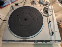
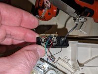
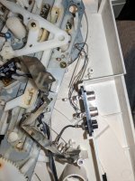
I really like my Technics SL-Q350 turntable other than the higher 60 Hz noise in the right channel. The left channel is great. I want to use it for ripping to digital with the pspacialaudio Stereo Lab software and I'm trying to get an 80 dB SNR in both channels. It uses T4P cartridges that I like, so I am wondering if it is possible to rewire the tone arm at all. The right channel has about 15 dB more hum than the left. I did my best to manage the wires that are easily accessible in the underside of the chassis, twisting the wires for each channel together tightly and keeping them away from other wires had no effect. So the only wire left is in the tone arm and the few inches that go through the gimble. Apparently the wires are far enough apart to create a loop area on just the right channel. The resistance of both channels to the cartridge is the same, around 0.5 ohms. Disassembly looks like hours of work and lots of parts, so I thought I would ask if it's possible to swap wires into that tone arm and T4P head shell?
Attachments
Quested DX3000
- By pacoloco
- Solid State
- 0 Replies
Hi i have this power amp Quested dx 3000, and looks like is very rare,i am triyng to find schematics cos i have a problem with one channela ,but i cant find anything ,i wropte to quested but at the moment they cant find information,so if somebody have informaton about this amp please let me know
thanks
thanks
Totem Hawk crossover design. Why tweeter polarity is reversed?
I bought a pair of Totem Hawk speaker. However, one of the tweeter is blown. And I ordered a new tweeter from my local Totem dealer. I removed the old one and install the new one and found that the original circuit has the polarity reversed. The crossover is a simply first order design. Can anyone tell me why the tweeter polarity is reversed? Also in the tweeter circuit, why do they used three resisters in parallel along with one resister in series? Can them just use one resister? Is it because a specific resistance value that they want to achieve?
thanks a lot in advance

thanks a lot in advance
Distortion in Measurement Microphones - actual measurements
As there was a lot of discussion about microphone distortion here recently and I'm actually working on a pressure chamber which can produce >160dBSpl ... I spent an afternoon to do some microphone measurements.
Setup
A pressure chamber is a device with a speaker membrane with a very small and 100% sealed front chamber. This pushes the resonance frequency of the 8" speaker to about 350Hz in my case - the volume is that small. But you can produce huge pressure changes now!
Measurements as always done with proper gear (APx515, Class1 Calibrator, Benchmark AHB2 Amp etc).
Measurement frequency is 250Hz (to be sure we are in 100% pressure chamber behaviour and it's the recommended calibration frequency by B&K and GRAS), stepped level sweep, 31 steps.
Check of the chamber - how much THD produces the speaker.
Such a pressure chamber produces stupendous SPL at very little membrane movement - so there is very little THD from the speaker. To check my limits I did the first 2 measurements with a GRAS 1/4" 40BD capsule with 2 different "preamps" (actually just impedance converters, they are just called preamps but there is no amplification).
That's the result.

There is a LOT of noise and some strange stuff between 115 and 135dBSpl going on with these 1/4" capsules - legit THD measurements are only starting from 140dBSpl and up. So we produce 150dBSpl with <1%THD and 160dBSpl <3%THD. We don't know if that's the speaker or the refmic! (I have an idea ...)
But we are sure about staying under 1% <150dBSpl and 3% <160dBSpl
So how are our microphones performing.

Here you see the linearity graph. 160dBSpl is easy for our 1/4" capsule. Not so for the other microphones ...
M50 gets to 145dBSpl - spec is 140dBSpl
M215 around 140dBSpl depending on capsule sensitivity -> preamp distortion. Spec is 135dBSpl.
I didn't bother to look after the Behringer Mic spec as it's just here as deterrent example - but >130dBSpl is actually not bad!
But what about THD?!
Here it is - the truth about reference microphone THD:

As expected ... don't use cheap measurement microphones for delicate measurements. They can't do them. The Behringer is out.
Interesting is that the Earthworks has higher THD as the M215! Noise area is up to about 105dBSpl (there is a lot of noise in the pressure chamber cause of it's sensitivity!!!) but then we get valid measurements. At the specified 140dBSpl max it has already 2% THD - that's A LOT! Studio microphones are normally specified with 0,5% THD, somtimes with 1% when the manufacturer wants to push it a little.
M215 - 135dBSpl is where the preamp starts distorting - that's not a limit of the capsule! Actually - it is when you take the 0,5% THD rule ...
BUT - one of the M215 amplifiers produces more noise as it should. Noise should be less as the M50 (dark green) but number 1 has more noise (light green). Will have to investigate, maybe just dirt in the high impedance area (these mics don't get pampered).
You can calculate your THD from this graph for lower SPL. -20dB -> 1/10th of THD. Even the Behringer follows that rule, it's how a condenser capsule SHOULD behave in theory. And they do!
So what about higher order harmonics?
tbc.
Setup
A pressure chamber is a device with a speaker membrane with a very small and 100% sealed front chamber. This pushes the resonance frequency of the 8" speaker to about 350Hz in my case - the volume is that small. But you can produce huge pressure changes now!
Measurements as always done with proper gear (APx515, Class1 Calibrator, Benchmark AHB2 Amp etc).
Measurement frequency is 250Hz (to be sure we are in 100% pressure chamber behaviour and it's the recommended calibration frequency by B&K and GRAS), stepped level sweep, 31 steps.
Check of the chamber - how much THD produces the speaker.
Such a pressure chamber produces stupendous SPL at very little membrane movement - so there is very little THD from the speaker. To check my limits I did the first 2 measurements with a GRAS 1/4" 40BD capsule with 2 different "preamps" (actually just impedance converters, they are just called preamps but there is no amplification).
That's the result.
There is a LOT of noise and some strange stuff between 115 and 135dBSpl going on with these 1/4" capsules - legit THD measurements are only starting from 140dBSpl and up. So we produce 150dBSpl with <1%THD and 160dBSpl <3%THD. We don't know if that's the speaker or the refmic! (I have an idea ...)
But we are sure about staying under 1% <150dBSpl and 3% <160dBSpl
So how are our microphones performing.
Here you see the linearity graph. 160dBSpl is easy for our 1/4" capsule. Not so for the other microphones ...
M50 gets to 145dBSpl - spec is 140dBSpl
M215 around 140dBSpl depending on capsule sensitivity -> preamp distortion. Spec is 135dBSpl.
I didn't bother to look after the Behringer Mic spec as it's just here as deterrent example - but >130dBSpl is actually not bad!
But what about THD?!
Here it is - the truth about reference microphone THD:
As expected ... don't use cheap measurement microphones for delicate measurements. They can't do them. The Behringer is out.
Interesting is that the Earthworks has higher THD as the M215! Noise area is up to about 105dBSpl (there is a lot of noise in the pressure chamber cause of it's sensitivity!!!) but then we get valid measurements. At the specified 140dBSpl max it has already 2% THD - that's A LOT! Studio microphones are normally specified with 0,5% THD, somtimes with 1% when the manufacturer wants to push it a little.
M215 - 135dBSpl is where the preamp starts distorting - that's not a limit of the capsule! Actually - it is when you take the 0,5% THD rule ...
BUT - one of the M215 amplifiers produces more noise as it should. Noise should be less as the M50 (dark green) but number 1 has more noise (light green). Will have to investigate, maybe just dirt in the high impedance area (these mics don't get pampered).
You can calculate your THD from this graph for lower SPL. -20dB -> 1/10th of THD. Even the Behringer follows that rule, it's how a condenser capsule SHOULD behave in theory. And they do!
So what about higher order harmonics?
tbc.
Motor run capacitors
- By saabracer23
- Parts
- 8 Replies
Very early on in my electronics heyday, I was replacing some capacitors in an old RTR I had and I replaced the electrolytic motor capacitors with other electrolytic, of same value. After I was done rebuilding it I ran it and a few seconds later I heard a big pop. That is when I learned that you can’t just put regular old electrolytic capacitors in place of ones rated for motor use. is the case the same for polypropylene? I see that many people now use poly propylene for the capacitors, do they need to be rated for that or pretty much any poly propylene work in that position?
I have a 2.5 µF at 250 V AC and a 6.8 µF at 125 V AC. I know that capacitor is ready for 400 V DC are also rated for 250 V AC, so could I just swap something like this in? Or is it absolutely necessary I get one rated for motor use.


Thank you,
Dan
I have a 2.5 µF at 250 V AC and a 6.8 µF at 125 V AC. I know that capacitor is ready for 400 V DC are also rated for 250 V AC, so could I just swap something like this in? Or is it absolutely necessary I get one rated for motor use.
Thank you,
Dan
Amp out as PSU
- Power Supplies
- 6 Replies
Hello all, here is a shot in the dark. Please excuse if a stupid question. This is related to my Cub Sandwich sub build
Let's say I wanted to keep the speaker passive and use if with an outboard amp. It's a very small cab in a system sealed by passive radiators. I have designed in a heatpipe to take hot air away from the motor vent. Is there a way to bleed off a lil bit of power from the speaker terminals to power a small fan to encourage air movement in the pipe?
I.e. an active fan inside a passive speaker without any other power supply for the fan
Thanks and regards
Randy
Variations of materials for internal lining, which is the best?
- By Pedroga
- Construction Tips
- 26 Replies
What is the best internal lining for sealed and ducted boxes?
Do sealed boxes really need internal lining?
I once made a sealed box and covered it with glass wool but I was never able to check whether or not it made a difference to the sound.
For ducted boxes with subwoofers intended for deep bass, what coating should I use?
Do sealed boxes really need internal lining?
I once made a sealed box and covered it with glass wool but I was never able to check whether or not it made a difference to the sound.
For ducted boxes with subwoofers intended for deep bass, what coating should I use?
Choosing the right Class D amplifier for me
I'm working on creating a "Wall Sequencer" that let users create their own beats.
I'm trying to get a budget friendly options to build the right Audio Setup.
I'm looking at the following:
The wall will be outside in the open desert.
My goal is to have a clear sound of mostly Electronic (Techno) Instruments, so clear sound and low frequencies are important for me less than volume (power).
I believe the setup should be 2.1 speakers.
Would love to hear your thoughts an ideas on how to get the right Class D for me.
I'm trying to get a budget friendly options to build the right Audio Setup.
I'm looking at the following:
- Professional Audio Amplifier Module 2.1CH TPA3255 Chipset Imported JRC2068 For Home Sound Systems For Subwoofer Speaker
- ZK-3002 TPA3255 Pure Rear Level Digital Amplifier Board Stereo 300W x 2, Bridged Mono 600W AMP Audio Music Power Amplifier Board
- YS-AS21 2*220W+350W 2.1 Channel BT Digital Power Amplifier Board TPA3255 AMP Subwoofer Treble Bass Tone Audio APP USB Function
- SAMP-200 Dual core TPA3255 High power 2 channel amplifier board 600W+600W
- UNISIAN TDA7498E Bluetooth 5.0 Amplifier Digital High Power 2*160W+220W 2.1 Channel Audio Power Amplifiers Board DC32V
- XH-A128 TDA7498E Digital Power Amplifier Board D12-32V 160Wx2 And 220W Stereo 2.1 Channel Amp Amplifier Board
- TDA7498E Built-in cooling Fan ZK-HT21 AUX Bluetooth-compatible 5.0 USB Stereo Audio Power Amplifier Board 2.1 Channel
- 220W+220W+350W High Power 2.1 Channel TPA3255 AUX USB Bluetooth Audio Power Amplifier Board Frequency Treble Bass Volume Control
- ZK-AS21 2.1 Channel TPA3255 Bluetooth Digital Power Amplifier Board Module High And Low Tone Subwoofer 220WX2+350W
- 2*220W+350W TPA3251 Bluetooth Power Amplifier Board 2.1 Ch Class D USB Sound Card Subwoofer Theater Audio Stereo Equalizer Amp
The wall will be outside in the open desert.
My goal is to have a clear sound of mostly Electronic (Techno) Instruments, so clear sound and low frequencies are important for me less than volume (power).
I believe the setup should be 2.1 speakers.
Would love to hear your thoughts an ideas on how to get the right Class D for me.
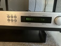
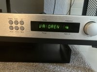
Creek Audio T50: LCD issue displays gibberish when brightness level is Off
- By gghodg
- Analogue Source
- 3 Replies
Hi folks,
Is this an issue with the LCD itself or the circuit? I am thinking of replacing electrolytic capacitors anyway as a preventative maintenance.
Another issue I’m seeing is brightness level will not adjust (stuck on High) in the AM band.
I’ve attached schematics to the T40, similar model. The LCD model on the T40 appears to be NEC FIP7A8S, so far no luck with finding this model on google.
Thanks.
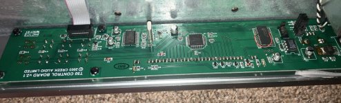
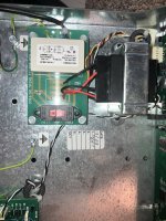
Photos of LCD brightness set to Off and Low, and T50 boards.
Is this an issue with the LCD itself or the circuit? I am thinking of replacing electrolytic capacitors anyway as a preventative maintenance.
Another issue I’m seeing is brightness level will not adjust (stuck on High) in the AM band.
I’ve attached schematics to the T40, similar model. The LCD model on the T40 appears to be NEC FIP7A8S, so far no luck with finding this model on google.
Thanks.
Photos of LCD brightness set to Off and Low, and T50 boards.
Attachments
A simplified method to implement digital frequency division using FIR filter in Windows system
Foobar2000 released the VST 2.x/3.x Adapter plugin on 2022-11-17, the latest version is 0.12, the plugin allows VST effects to be used as a DSP in foobar2000, VST/VST3 can be used. In this way, the foobar2000 can directly call to load the FIR filter as a DSP digital crossover. It's extremely simple and plays smoothly.
Hardware:
One PC. One multi-channel DAC.
Software:
System software version: Windows7 SP1 or later. Install the sound card driver.
Foobar2000 version V1.6 or later, preferably V2.1.5.
VST 2.x/3.x Adapter Current version: 0.12。
convolver4-4vc++。 convolver4-4vc++ is an open-source, high-performance Windows application for applying a finite impulse response (FIR) filter.
rePhase。 Speaker phase linearization, equalizer, and FIR filter generation tools.
First, install convolver4-4vc++ on your system. Then, the administrator runs rePhase to generate the FIR filter file (low-pass .wav, bandpass .wav, high-pass .wav), and uses a text editor to generate the txt text file of config.
Install foobar2000V2.1.5 on the system, download and install the VST 2.x/3.x plug-in, add the VST 2.x/3.x plug-in in the DSP management of the preferences, configure the VST 2.x/3.x plug-in, add the folder where the installed convolver is located, select convolverVST (VST v2 32bit), and display the VST Effect in the pop-up format Click Filter/config in the configuration window, select the config file generated earlier, OK. Select the default speaker exclusive in the output and play it.
Audio Technica AT-LP120USB Tone arm weight?
- Analogue Source
- 0 Replies
Purchased a decent Audio Technica turntable with the stock cartridge and want to replace the original cartridge with one I have owned for many years. I am concerned with the additional weight of the Pickering XV-15 cartridge with the D1200 stylus and brush that I want to use. The weight of the Audio Technica cartridge with headshell and hardware is 15.525 grams. The weight of the Pickering with head shell, brush and hardware is 17.8 grams. The stock Audio Technica head shell and hardware is 10.7 grams.
The only information I was able to come up with is the Audio Technica can use a cartridge between 3.5 grams and 8.5 grams. I can find no information as to compliance or tone arm weight.
Haven't used it yet as I'm still trying to find more information so any help or comments would be appreciated.
The only information I was able to come up with is the Audio Technica can use a cartridge between 3.5 grams and 8.5 grams. I can find no information as to compliance or tone arm weight.
Haven't used it yet as I'm still trying to find more information so any help or comments would be appreciated.
Hi from France
- By Zozor
- Introductions
- 9 Replies
Hi there,
Am coming from France, south France, Montpellier.
I am a collector of audio devices but mainly of CD players.
I chose this forum because it seems to me to be the most in-depth in its discussions.
Thank you for welcoming me.
Am coming from France, south France, Montpellier.
I am a collector of audio devices but mainly of CD players.
I chose this forum because it seems to me to be the most in-depth in its discussions.
Thank you for welcoming me.
Pioneer PD-106 : CD which does not turn systematically
- By Zozor
- Digital Source
- 5 Replies
Hi there,
I need your suggestions please. It's a curious failure, at least for me.

Most of the time, we insert a disc (in perfect condition) and it fits correctly in its slot.
The disk does not turn, we hear the actuator click while it makes several movements, then nothing and the display indicates zeros.
We eject the trapdoor and its disk several times AND! the disc starts to spin, the Toc is read immediately.
We insist on the "read" button, the actuator clicks once, the disc does not turn.
We take the disc out several times, but this time we press the “play” button directly.
At some point, reading will start !
The entire disc can be played perfectly, without skipping. You can skip back and forth between tracks, change tracks at will !
As soon as you stop the disk, it will not restart. We eject the disc several times and wait for the next reading ! 👽
Notes :

- The soldering under the card was bad originally. it is poor in tin and under the soldering iron, the component legs refuse to solder.
We see in this photo the difficulty :


- I also looked under the optical unit. Maybe a problem with the cms capacitors?
I didn't see anything special on the weld side.

- I then saw that the rubber suspensions of the chassis were all dead !

- I temporarily replaced these suspensions with plumbing washers on hand I had. No improvement.
In any case, even if the chassis is poorly suspended or crooked, the spindle remains aligned on its common chassis facing the optics.
isn't it ?
(and the CD did not rub when turning)

I find it hard to question the optics since when the reader works, it works perfectly.
It's a PEA1335, unobtainable or overpriced !
What can I do now ? Can you help me please ?
Doc here : https://elektrotanya.com/pioneer_pd-106_sm.pdf/download.html
I need your suggestions please. It's a curious failure, at least for me.
Most of the time, we insert a disc (in perfect condition) and it fits correctly in its slot.
The disk does not turn, we hear the actuator click while it makes several movements, then nothing and the display indicates zeros.
We eject the trapdoor and its disk several times AND! the disc starts to spin, the Toc is read immediately.
We insist on the "read" button, the actuator clicks once, the disc does not turn.
We take the disc out several times, but this time we press the “play” button directly.
At some point, reading will start !
The entire disc can be played perfectly, without skipping. You can skip back and forth between tracks, change tracks at will !
As soon as you stop the disk, it will not restart. We eject the disc several times and wait for the next reading ! 👽
Notes :
- The central motor has been checked with an external power supply and is working well. I added a drop of oil to the axle.
- I looked at the cable connections to the motherboard, but no false contact
- Using the multimeter on the central motor connector of the motherboard, I have between 4 and 2 volts when the disk is spinning. No voltage when the disk is not spinning.
- Belts have been checked, no problem.
- I also noticed that the LA6520 (ic202) is hot when the second one is cold (there are two on this card)
- The control panel is not the cause, we see the actuator move with each selection.
- There is nothing visually suspicious about the electronic components.
- The soldering under the card was bad originally. it is poor in tin and under the soldering iron, the component legs refuse to solder.
We see in this photo the difficulty :
A view of the entire board :I reworked a majority of solders correctly and even on the chips
- I also looked under the optical unit. Maybe a problem with the cms capacitors?
I didn't see anything special on the weld side.
- I then saw that the rubber suspensions of the chassis were all dead !
- I temporarily replaced these suspensions with plumbing washers on hand I had. No improvement.
In any case, even if the chassis is poorly suspended or crooked, the spindle remains aligned on its common chassis facing the optics.
isn't it ?
(and the CD did not rub when turning)
It's only with the revision of the soldering of the board that I find the best. The disc is read once in five, instead of once in 15.
I find it hard to question the optics since when the reader works, it works perfectly.
It's a PEA1335, unobtainable or overpriced !
What can I do now ? Can you help me please ?
Doc here : https://elektrotanya.com/pioneer_pd-106_sm.pdf/download.html
Biamping 8 ohm 3-way with Denon AVR (min 6 ohm)
- By daveing
- Electronic Design
- 5 Replies
Hi Diyers,
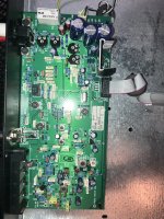
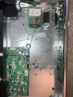
I have a MiniDSP 8-channel processor, a Denon AVR-3083 (with pre-in for each channel) and a pair of KEF Q7s. I'm getting set up for bi-amping and bass management trough the MiniDSP. The Q7 is bi-ampable - splitting the woofer from the coaxial mid-hi arrangement. The Q7 nominal impedance is 8 ohm. I've just measured each driver separately (Q7 disassembled for refinishing) and they each measure 3 ohms woofer, mid & hi.
The AVR-3803's recommended minimum impedance per channel is 6 ohm.
Am I going to destroy my cheap old AVR if I biamp with it?
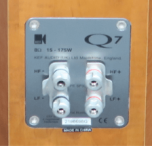
I'm surprised the binding post bridges seem to be series linking the drivers to get 8ohm. I would have thought positive to positive and negative to negative binding post bridges are a parallel connection. (drivers at 16ohm each...) Maybe KEF internally flipped the connections so we are getting 4 +6 ohm = about 8 ohm.
Thoughts?
Thanks
I have a MiniDSP 8-channel processor, a Denon AVR-3083 (with pre-in for each channel) and a pair of KEF Q7s. I'm getting set up for bi-amping and bass management trough the MiniDSP. The Q7 is bi-ampable - splitting the woofer from the coaxial mid-hi arrangement. The Q7 nominal impedance is 8 ohm. I've just measured each driver separately (Q7 disassembled for refinishing) and they each measure 3 ohms woofer, mid & hi.
The AVR-3803's recommended minimum impedance per channel is 6 ohm.
Am I going to destroy my cheap old AVR if I biamp with it?
I'm surprised the binding post bridges seem to be series linking the drivers to get 8ohm. I would have thought positive to positive and negative to negative binding post bridges are a parallel connection. (drivers at 16ohm each...) Maybe KEF internally flipped the connections so we are getting 4 +6 ohm = about 8 ohm.
Thoughts?
Thanks
Attachments
Ian Canada's I2S to PCM Interface
- By batteryman
- Swap Meet
- 5 Replies
I have one for sale, unused and supplied with interconnects. (I bought three and used two to grreat effect)
Also on ebay:
https://www.ebay.co.uk/itm/285433001874
SPDIF to I2S adaptor also listed.
Also on ebay:
https://www.ebay.co.uk/itm/285433001874
SPDIF to I2S adaptor also listed.
DIY Shielded Phono Cable, wire recommendations?
- By kouiky
- Analogue Source
- 6 Replies
Hello DIYers,
I'd like to make a shielded cable to connect a tonearm (low output MC cartridge) to an MC phono stage. The phono input is unbalanced (sigh).
A few cables I've looked at are the Mogami W2534 and the W2893, both shielded quad. Another option is Canare L-4E6S sheilded star quad.
If there is a better choice of wire and preferred shield termination style for this application, just lemme know!
Meanwell EPP 300 48 and Paralleling for TPA3255 build
- By Gaspar74
- Power Supplies
- 2 Replies
I have two of these guys, I cant seem to find info on if these can be safely paralleled to double current and if so whats best practice in doing so?
Desktop full range
- By lezzmeister
- Full Range
- 8 Replies
So I had these on my desktop, and they are deceased after 2 decades of loyal service. Also a tad large, but I liked them a whole lot.
So after a lot of searching and reading (sitting close and phase, open baffle and wall, imaging, that tweeter has ehm questionable reviews apparently), I think the best and easiest option is a nice fullrange in closed box, either a Fane or a Sica, this is (probably?) as large as I can get away with next to my screen. But I'd like to avoid an absolutely huge box.
What is the smallest housing for either of these that I can get away with, is 45-47 liter good? Is it stupid to even ask and am I then better off with 10 inch drivers? About 50% music, 50% games if relevant. I just want to get rid of these crappy Logitechs. Recommend other drivers if a lot better for a small box but try and cap it at say 2×-3× the price.
Quarter Wave Absorber
- By Maxine01
- Room Acoustics & Mods
- 2 Replies
Hello, I currently has an idea to dampen standing waves in a room, but I didn't find much content about it, to know if this idea would work.
So, the idea is to make a transmission line with one extremity open and the other closed, where the open extremity is the entrance of the sound from the room, so it can pass through the path that will probably have a conicity that decreases towards the closed extremity.
So, this idea came to me when I was thinking about a way to dampen or absorb low-frequency standing waves in a room.
The first alternative that came to me were bass traps, but research showed me that for bass traps to work with good efficiency from 50 to 100 or 200 hz, they would have to be very thick, in addition to the expense of large amounts of rock wool or glass wool would start to get tall.
The second alternative that came to me were the Helmholtz absorbers, but this type of absorber would not be ideal for me, as it only works with a very small range, which would make me have to make several resonators each tuned to an ideal frequency, and they also seem to me to be more complex than the quarter wave absorbers.
So, if this idea can work to dampen or absorb the stationary waves that are in the corners of my room or in other regions of my room, then could you show me content about this type of absorption or if it has ever been tried?
If this absorber idea can work, I'll talk more about my room.
Thermal pad for TO264 (ulTIMiFlux)
Hello,
Anyone have experience with these thermal pads? I need buy a 32 pcs.
https://www.tme.com/us/en-us/details/cd-02-05-264/heatsinks-equipment/wakefield-thermal/
Anyone have experience with these thermal pads? I need buy a 32 pcs.
https://www.tme.com/us/en-us/details/cd-02-05-264/heatsinks-equipment/wakefield-thermal/
Toroidal Power Transformers Questions
- Power Supplies
- 78 Replies
Greetings all. I just joined this group. My background is researching designing toroidal transformers and have extensive knowledge of same. From what I have read so far, there seems to be some misinformation. Pls post any toroid questions and I will do my best to answer them.
Are there any analog to digital DIY projects?
- By sbelyo
- Analogue Source
- 3 Replies
Are there any DIY analog to digital projects, boards or kits out there? I would love to get something like the Mytek Brooklyn ADC (Not DAC) but it's discontinued. That leaves me with searching for a used one or seeing if there is a project for one.
I need help identifying parts on a generic Korean 5k board
- Car Audio
- 4 Replies
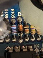
I am having trouble identifying a diode that was physically burned by a cooked power supply mosfet. I could not get clear photo of the diodes in the power supply section but it looks exactly like D3 in the photo, no numbers just black on one end and a thin gold stripe. It has .6 voltage drop one way and reads open when I reverse the leads. I was thinking it’s a 4148. Any thoughts?
Attachments

What the heck? It's less than lunch!
Just bought one of these! Yes, it's stereo, not mono. $6! Free shipping!
Why not? 😎😎😎
Promotion TDA7297 Whi Fi Noiseless 2 0 Audio Power Amplifier Board Max 30W 30W | eBay
Why not? 😎😎😎
Promotion TDA7297 Whi Fi Noiseless 2 0 Audio Power Amplifier Board Max 30W 30W | eBay
Is there a reason to terminate a connection at the binding post vs. the transformer?
- By SoaDMTGguy
- Tubes / Valves
- 5 Replies
See attached schematic.
Audio Research terminates the feedback loop connections at the binding posts. Is there any reason they chose that vs. terminating at the transformer? The area behind the posts is cramped, and terminating the wires at the transformer also reduces overall wire length. I don't want to second guess ARC, I'm sure they have their reasons, but it seems electrically equivalent. Am I missing something?
Audio Research terminates the feedback loop connections at the binding posts. Is there any reason they chose that vs. terminating at the transformer? The area behind the posts is cramped, and terminating the wires at the transformer also reduces overall wire length. I don't want to second guess ARC, I'm sure they have their reasons, but it seems electrically equivalent. Am I missing something?
Attachments
Ian Canada HDMIPro => Topping D90 / Ian Canada TransportPiAES and Gentoo Player
- Digital Line Level
- 12 Replies
I'm new(ish) to using digital streaming. I had been successfully using Ropieee through a Raspberry Pi over the last 3 years or so. I used various DAC hats or USB outputs to various DACs.
I've now expanded my horizons, and I'm trying out some new things that I desperately do not wish to screw up.
After assembling some of the Ian Canada parts into a very basic setup, I have the Gentoo Player on the Raspberry Pi configured for USB output to a DAC. I set it up as a Roon Bridge, and it seems to be working quite well.
Now, I want to try out the other "fancy" Ian Canada parts to output the signal to the DAC properly over the various interface options.
A few (okay a lot of) questions:
First the I2S

In the manual for the Topping, it shows the following for phase:

It would seem that I would need to reverse the phase with the D90 (or just remember to do it in Roon, I think) - no big deal.
What's odd (to me) is that it shows the following for DSD:

If I'm interpreting this correctly (highly suspect) the two (Ian's board and the D90 with DSD) cannot match. I can either have the phase reversed or the channels reversed, correct? I don't play a lot of DSD, but I'd like to have it set up properly.
It seems like it may be easiest to change the DSD to DSDR Data to get the channels correct. I can leave the phase alone. It would be inverted for both types. Then, I can just leave the phase inverted in Roon, if I actually care at all about absolute phase... which... I don't really, but...
OR
Are those settings independent of each other? i.e. if I swap the phase in the preceding step, it ALSO applies to the DSD?
I can test all of this, but it would be nice to not need to fool with testing phase.
So, if anyone knows, I'd be grateful.
-------------------------------------------
Next the AES
Onto the one that I really don't have a clue about... Gentoo Player with the TransportPiAES.
Do I still leave the "DAC" in Gentoo Player as generic I2S when I swap over to that?
Also, does anyone know how to use the Ian Canada I2S and the AES boards in a stacked configuration? I'd love to have both options permanently mounted, so I don't have to swap back and forth. However, the Masterclock from the Fifopi can only go to one thing, I think. Any advice is appreciated.
Just getting the Gentoo Player set up and running was a monumental task. In hindsight, it's easy as Pi It just had a steep learning curve for me. It's playing now, and it hasn't glitched, so... I'm leaving it alone... until I may need to change it for the AES board...

Edited to insert thumbnails vs. have the massive pics.
I've now expanded my horizons, and I'm trying out some new things that I desperately do not wish to screw up.
After assembling some of the Ian Canada parts into a very basic setup, I have the Gentoo Player on the Raspberry Pi configured for USB output to a DAC. I set it up as a Roon Bridge, and it seems to be working quite well.
Now, I want to try out the other "fancy" Ian Canada parts to output the signal to the DAC properly over the various interface options.
A few (okay a lot of) questions:
First the I2S
- I assume in Gentoo player one would select the "DAC" as Generic I2S, correct?
- Then, as but one example, I have a few DACs. One is a Topping D90. I noticed that the pinout for the Ian Canada board is:
In the manual for the Topping, it shows the following for phase:
It would seem that I would need to reverse the phase with the D90 (or just remember to do it in Roon, I think) - no big deal.
What's odd (to me) is that it shows the following for DSD:
If I'm interpreting this correctly (highly suspect) the two (Ian's board and the D90 with DSD) cannot match. I can either have the phase reversed or the channels reversed, correct? I don't play a lot of DSD, but I'd like to have it set up properly.
It seems like it may be easiest to change the DSD to DSDR Data to get the channels correct. I can leave the phase alone. It would be inverted for both types. Then, I can just leave the phase inverted in Roon, if I actually care at all about absolute phase... which... I don't really, but...
OR
Are those settings independent of each other? i.e. if I swap the phase in the preceding step, it ALSO applies to the DSD?
I can test all of this, but it would be nice to not need to fool with testing phase.
So, if anyone knows, I'd be grateful.
-------------------------------------------
Next the AES
Onto the one that I really don't have a clue about... Gentoo Player with the TransportPiAES.
Do I still leave the "DAC" in Gentoo Player as generic I2S when I swap over to that?
Also, does anyone know how to use the Ian Canada I2S and the AES boards in a stacked configuration? I'd love to have both options permanently mounted, so I don't have to swap back and forth. However, the Masterclock from the Fifopi can only go to one thing, I think. Any advice is appreciated.
Just getting the Gentoo Player set up and running was a monumental task. In hindsight, it's easy as Pi
It just had a steep learning curve for me. It's playing now, and it hasn't glitched, so... I'm leaving it alone... until I may need to change it for the AES board...Edited to insert thumbnails vs. have the massive pics.
Telefunken E88CC Variants
- By marceljs
- Tubes / Valves
- 28 Replies
Hi all!
I recently acquired a project preamp without documentation which uses sixpentodes dual triodes (two in phono stage plus four in linestage).
I assumed all would be the same E88CC, and prior to turning it on, proceded to test the tubes on my TV-7U/D. Four are Telefunken, one Siemens, and one sans-branding (likely Chinese).
When I began testing, two showed no conductivity for both triode sides, which led me to question whether they were in fact E88CCs. Of course they lack markings other than the Telefunken diamond and country of manufacture.
What's odd is that the two mystery tubes were not in the phono stage, but instead within the linestage section, which relies on matched pairs for the two channels.
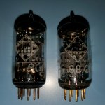
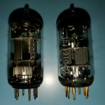
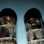
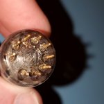
Attached is a comparison of the tube in question as well as a known, labeled Telefunken E88CC. The known E88CC has a getter plate supporting the halo post, whereas the tube in question does not. I'm not familiar enough with 9-pin tubes - much less Telefunken models to identify whether this is just another variant or a different tube altogether, so pitching this out to the experts 😉.
In the attahed images, the known E88CC is the one with gold pins and the mirror image of the number "11" inside its diamond on the underside.
Thanks!
I recently acquired a project preamp without documentation which uses six
I assumed all would be the same E88CC, and prior to turning it on, proceded to test the tubes on my TV-7U/D. Four are Telefunken, one Siemens, and one sans-branding (likely Chinese).
When I began testing, two showed no conductivity for both triode sides, which led me to question whether they were in fact E88CCs. Of course they lack markings other than the Telefunken diamond and country of manufacture.
What's odd is that the two mystery tubes were not in the phono stage, but instead within the linestage section, which relies on matched pairs for the two channels.
Attached is a comparison of the tube in question as well as a known, labeled Telefunken E88CC. The known E88CC has a getter plate supporting the halo post, whereas the tube in question does not. I'm not familiar enough with 9-pin tubes - much less Telefunken models to identify whether this is just another variant or a different tube altogether, so pitching this out to the experts 😉.
In the attahed images, the known E88CC is the one with gold pins and the mirror image of the number "11" inside its diamond on the underside.
Thanks!
Attachments
Acoustat Interface MK-121-2 - Minimizing the Bias Transformer Hum Noise
- By John Tulett
- Planars & Exotics
- 0 Replies
Preface
* Initially I experimented with grommets to modify the bias transformer mounting, but the most effective result came from using rubber anti-vibration studs to isolate the vibrations (Fig. 1).

Figure 1. Elesa VD1-1510M4 (left) not used, and Elesa VD1-1515M4 (right) used in this installation.

Table 1. Specifications of Elesa Type VD1 Rubber Vibration Dampers - dimensions in mm.
* A full set of specifications for the VD1 series can be obtained from the attached specification sheet. An optional stainless-steel version VD1-SUS is available for wet or corrosive applications but isn't needed here.
Preparation

Figure 2. Pre-assembly showing wiring harness for connecting both ends of each VD1-1515M4.

Figure 3. Partial assembly, VD1-1515M4 pair and wiring harness attached to transformer base.

Figure 4. Bias transformer reinstalled with new VD1-1515M4 pair and ground wiring.
* Fortunately, this installation using the VD1-1515M4 pair allowed just enough clearance between the bias transformer housing and the large 50 K ohm resistor (Fig. 4).
Results
- This report is a follow-up to, "Acoustat Magne-Kinetic Interface MK-121-2 - A Successful Restoration" https://www.diyaudio.com/community/...ace-mk-121-2-a-successful-restoration.404764/
- As stated in this restoration report, "Initial Symptoms. When powered up, annoying hum noise coming from both interfaces." This noise issue was addressed in section "Minimization of 50 Hz induced hum noise" accompanied by Figures 19 and 20 in the report, whereby applying synthetic rubber sheeting to the chassis was effective in reducing the hum noise.
- However, I was intrigued by the comment from Mr. AAM from his review of my report where he kindly replied with, "And speaking of the bias transformer, later units had the transformer mounted on rubber grommets, alleviating the "chassis hum" you experienced."
- As these are my only pair of Acoustat electrostatic loudspeakers having purchased them new in 1980, I would never have known about this subsequent change to the transformer mounting. So, thanks to Mr. AAM for sharing this information, it got me thinking!
- While the initial restoration report addressed reducing the hum noise, the purpose of this report is to minimize the noise vibrations at its source.
- Without having information about how the transformer mounting was changed in subsequent production or the parts involved, another purpose of this report is to share with our members an inexpensive solution using commercially available parts.
* Initially I experimented with grommets to modify the bias transformer mounting, but the most effective result came from using rubber anti-vibration studs to isolate the vibrations (Fig. 1).
Figure 1. Elesa VD1-1510M4 (left) not used, and Elesa VD1-1515M4 (right) used in this installation.
- Two vibration dampers are required for each bias transformer, or total 4 for the pair of speakers.
- Of the two series of vibration dampers purchased, VD1-1510M4 of rubber height 10mm and VD1-1515M4 of rubber height 15mm, I decided to first try the VD1-1515M4 as it had the softer spring constant (Table 1). In the event of insufficient clearance between the bias transformer housing and the high-voltage board with the VD1-1515M4, then I would change to the lower profile VD1-1510M4.
- An M4 thread type was chosen as the M4 diameter was close to the diameter of the original mounting hardware, whereas the next size up M6 would require enlarging the chassis holes.
Table 1. Specifications of Elesa Type VD1 Rubber Vibration Dampers - dimensions in mm.
* A full set of specifications for the VD1 series can be obtained from the attached specification sheet. An optional stainless-steel version VD1-SUS is available for wet or corrosive applications but isn't needed here.
Preparation
- Safety. Ensure the AC power cord is disconnected, and the high voltage circuit has been fully discharged.
- A consequence of the rubber damping material is it isolates the earth connection between transformer housing and chassis. Proper grounding is very important, both for safety and to complete the connection to the bias high voltage.
- To re-establish the ground connection a small wiring harness was constructed (Fig. 2).
Figure 2. Pre-assembly showing wiring harness for connecting both ends of each VD1-1515M4.
Figure 3. Partial assembly, VD1-1515M4 pair and wiring harness attached to transformer base.
- The inside surface of the interface's chassis was lightly sanded around the mounting holes to ensure a bare metal contact with the grounding wire lugs.
- Finally, the bias transformer with wiring harness and anti-vibration studs was installed back in the interface using M4 fastening hardware (Fig. 4).
Figure 4. Bias transformer reinstalled with new VD1-1515M4 pair and ground wiring.
* Fortunately, this installation using the VD1-1515M4 pair allowed just enough clearance between the bias transformer housing and the large 50 K ohm resistor (Fig. 4).
Results
- After installing these parts and upon powering up I was pleasantly relieved all transformer hum noise is gone, both interfaces are now dead quiet. Considering the parts cost less than $5 per interface this was a worthwhile modification.
- Previously when placing your hand on the interface chassis you could feel the vibrations, but this is greatly diminished now.
- Regarding the initial approach of attaching synthetic rubber isolation sheets to the chassis, this was left in place as it does no harm.
- Side note, while the reduction in hum noise was clearly apparent, I was not expecting any changes in the audio sound quality. But there is a very subtle improvement with a clearer, more open sound. I don't think I'm imagining things as I have owned these speakers for 44 years and am accustomed to their amazing sound quality, on the other hand I cannot quantify in measurements what I have heard. While it's difficult to say, one theory might be the previous mechanical vibrations throughout the chassis impacted the performance of different components, whereas these chassis vibrations are now considerably diminished.
- Why it took me so long to act on Mr. AAM's comment regarding transformer isolation? To be honest the biggest priority after restoring the interfaces was repairing the multiple broken stator wire joints, documented in "Acoustat Stator Wire Repair: Hints and Lessons Learned" and this effort took over a year to complete before I could address the transformer hum. https://www.diyaudio.com/community/...wire-repair-hints-and-lessons-learned.404881/
- As mentioned, I purchased two series of vibration dampers, VD1-1510M4 of rubber height 10mm which I kept as spare, and VD1-1515M4 of rubber height 15mm which I installed and documented in this report. Should one day the VD1-1515M4 rubber become soft and the bias transformer begins to sag, my plan is to change to the lower profile VD1-1510M4 having a higher spring constant (Table 1).
- While not documented in this report, other makes of similar anti-vibration hardware could give similar results.
- VD1 series, Japanese. https://www.imao.co.jp/files/ja/pdf/vd1.pdf
- VD1 series, English. https://www.imao.com/files/en/pdf/vd1-e.pdf
Attachments
For Sale My_ref Fremen 1.02 gainclone power amplifier dual mono. Working well
- By gilbodavid
- Swap Meet
- 1 Replies
Working very well. Good quality parts.
£100 Ono


£100 Ono
Military-Grade 814 Valves for Sale
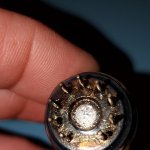
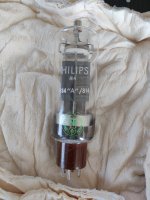
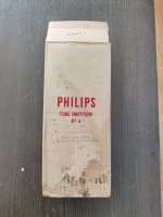
Fellow DIYers! I am reaching out to you regarding a unique collection of 814 valves that I currently possess. These valves were acquired from France some time ago, and I have meticulously preserved them since then.
However, as life often leads us down unexpected paths, my circumstances have shifted, prompting me to reassess my priorities. Consequently, I find myself in the position of needing to part with these valves.
I am posting here to inquire whether you might be interested in acquiring this collection. The valves are in impeccable condition, having been carefully maintained, and I believe they could be of value to someone with a passion for such items.
Given my impending relocation to another country, I am eager to find a new home for these valves. If you are interested or require any further information, please do not hesitate to reach out to me.
You can read more about this tube here: https://www.bartola.co.uk/valves/2013/11/23/814-se-a2-amplifier/
Thank you for considering this opportunity.
Attachments
DIY KEF Blade Coax + Dayton RS180 midbass array in baffle wall
I have 3x KEF Blade Coax drive units that I want to use in a new setup in a new house, together with 8x Dayton RS180 per side in a baffle wall.
(I have 3 of these nice coaxes, so there will also be a center speaker with the same setup but with only 4 RS180 mid)
Does anyone here know how to calculate spacing and possibly distance from floor and ceiling, and possibly have general thoughts about solutions?
Appreciate feedback and discussions!
My thoughts are in this way to solve a lot of the room nodes in the elevation plan. Split frequency will be considered, but around 4-500hz possibly with some overlap.
Originally Kef Blade is shared at 320hz, but I personally feel it is a bit low. There will be a subwoofer to take the bass area.
I have a Minidsp OpenDRC-DA8 for active crossover incl FIR.
See picture for alternative placements of mids.
In one set-up, the coax is at a height of approx. 1.25m, which I feel is somewhat high compared to the approx. 1m sitting position?
Attachments

Would a small folded midrange horn work?
- By freddi
- PA Systems
- 106 Replies
For Eminence's Delta 10A - say either a mini-La Scala ~ 15" cube or a "C" horn. If you've something in this ballpark I'd like to see the plan. Simpler is better.
just like to have a fun toy - one of Dr. Edgar's first Speaker Builder Magazine's articles concerned a folded midhorn.
just like to have a fun toy - one of Dr. Edgar's first Speaker Builder Magazine's articles concerned a folded midhorn.
Attachments

A Schade feedback PP design for GU50 tubes.
- By Globulator
- Tubes / Valves
- 3 Replies
Hi All,
As I was tidying up my workshop, I naturally came across an old Music Angel XD-800MkII for EL34's that I'd bought as a DIY project, without tubes, but with case and transformers. GU50 was (is!) the tube I wanted to use.
So I'd merrily started this about a decade ago, but then got distracted onto something else, and never managed to get back to it. As such, it needs tidying up, I.e populating with tubes, and a circuit, etc.
So the original Music Angle (KT88) schematic floats about, and there's the Dynaco ST70 design which is nice, but that's all been done before, and my original concept was to build a local feedback PP, due to the wonderful sound from my local feedback SE.
Anyway, if I just built old stuff, where would I be? Surrounded by nice, working things? The horror..
So anyway after a few false starts and dead ends (LTPs, I'm looking at you!), this is what I came up with. LtSpice only so far.
The 'slightly unconventional' anode resistors for the 6AU6's (which I'm pretty sure I have in stock, from an old raid on a Tek 545b) to B+ is to give it a 'more CCS like' anode load, without having to add Yet More Bits'.
Caveats: I'm not 100% sure of the B+ voltage. Or the output transformers. Or really, the tube models.. but I've attached them.
The tubelibrary I downloaded from the tube Spice model thread, but I re-wired the GU50 model to match the tetrode symbol. I'm not sure why they don't use the pentode symbol, perhaps some SPICE vs LTSPICE thing.
So I don't get much feedback in there, 6dB or so, but I'm low on gain. But at least this concertina + Schade resists the temptation to turn into an oscillator, so that's encouraging. I could add an input stage, of course, but that's another stage, more distortion and more bits. No feedback beyond the primary, as that would be madness 😆
I did try the GU50 in triode mode too, but that was hopeless. In Pentode mode literally everything is better 😍. This design has a wonderful soft clipping too, tubes seem far more 'elastic' than MOSFETs !
Tubes are chosen as to what I already have, a sure fire method I use to ensure I can build stuff...
Please point out any easy fixes, improvements, etc, as in my ideal dream world, I'll build it and it'll be magnificent.
At some point I'll send a small AC signal into the transformers and work out what the ratios might be too. 🔬
Biasing is a bit glossed over, it's awful in the original, but if anyone has a good circuit for PP tube balance (Pot 1) and level (Pot 2) please can you post it? A handy method to casually null the PP magetic field would be cool, with absolute level setting being demoted to a 'baseplate off' think as that drifting doesn't worry me.
All comments welcome, many thanks in advance!
Attachments
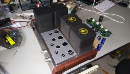
For Sale IRD MB-100 Monoblocks Amps
Selling this pair of IRD MB-100 amps. 100 watts Class AB into 8 ohm and 200 into 4 ohm.
I replaced the chip on one of the amps.
Asking $350 and I’ll ship anywhere in the CONUS for free.
I replaced the chip on one of the amps.
Asking $350 and I’ll ship anywhere in the CONUS for free.
Attachments
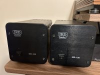
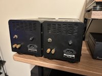
How would you drive an EL509 in enhanced triode mode.
- By Bas Horneman
- Tubes / Valves
- 200 Replies
I've seen the late Tim's 859. And he uses a cathode follower. I'm not sure he would do it the same if he were to design it today. Though if a pcb was available I would have used that design. But it will become a rats nest if I build it point to point. But I digress.
How would you do it today? Perhaps a "power drive"?
Power Drive | Tubelab
I have few STU9HN65M2....
My output transformer is going to be a One Electron UBT-1.
How would you do it today? Perhaps a "power drive"?
Power Drive | Tubelab
I have few STU9HN65M2....
My output transformer is going to be a One Electron UBT-1.
Attachments
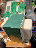
REL Studio II relay clicking
- By mjz3348
- Subwoofers
- 6 Replies
I powered down and unplugged my working REL Studio II for a planned power outage to repair a utility pole. Two hours later, when I turned the sub back on, the drivers relay began to click on/off. No sound could be heard except for a brief moment when the relay tried to connect the speaker drivers to the audio circuits. Needless to say, my sub is no longer working.
Visual inspection of the board show the caps to be in like new condition (no bulging or leaks anywhere). In fact the whole board looks brand new.
This sub was always left on and only turned off either due to infrequent power outages (storms) or when away for an extended time. Otherwise, the powered sub is always on.
Has anyone experienced this where only the relay is faulty or is it the power supply causing the clicking? I haven't tested any voltages yet needing advice on what/where to test. See image below for the relay picture. I can't find a schematic for this unit.
I did measure the relay's coil voltage and it fluctuates with each click - rising to a few volts then falling to zero. My digital meter is not fast enough to catch it because the click is so fast.
Thanks
WinISD: Sealed box construction for midrange (Questions)
- By Pedroga
- Software Tools
- 13 Replies
It was very recently that I started studying speakers and the hi-fi scene. I read in an article recently that when it comes to a sealed midrange box, the QTC has to be between 0.5 and 0.7. So far so good, but when I put any example midrange in winISD the internal volume of the box is very low... around 3 liters and I've seen examples on this forum of boxes with a volume of 7 liters. Midrange 4"
Attachments
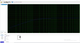
BTK5-120 by YOK amp help
- By Deadly Sones
- Car Audio
- 3 Replies
Good afternoon,
I've NEVER seen an amp like this one. It has 2 damaged output sections. There are no board designations and just about everything important has been defaced. The amp is sold under the name OG Audio.
The output transistors seem to be IRF640As. Can I use IRL640As?
I've circled what I believe to be the drivers... no idea what they are though... any insight??
Thanks in advance!!
Attachments

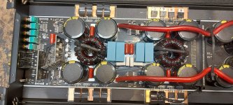
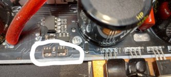
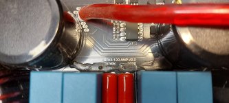
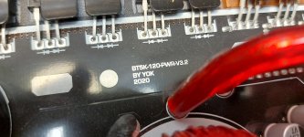
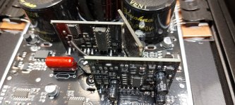
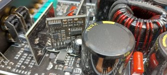
For Sale 01a preamplifier
- By Geluidloopt
- Swap Meet
- 3 Replies
Checking to see if there is any interest in this 01a preamplifier:
Made with boards designed by Radu Tarka
HV supply with CLC filter and regulated a la Salas
Filament bias with separate filament supplies, rod coleman boards and Mills cathode resistors
Gyrator and follower boards for low output impedance with FT-3 Teflon caps and Mundorf Silver/Gold/Oil output caps
Tubes are mounted on separate damped platforms
Stepped ladder attenuator for volume control
Included are 1x pair of 301a globe, 1x pair of 201a globe and 1x pair of 01a ST
I've always used it with one source and left the provision for 3 inputs total with a selector switch, if interested will wire it up.
PT can be used as 230V or 110V
SOLD
Attachments

XTR 4000.1D
This amp has rail voltage but the voltage for the op-amp is missing.The circuit that produces that voltage is there a tap from the transformer that feeds it or it’s tap from the rail?
Any suggestions
Any suggestions
Attachments
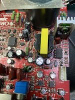
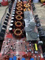
WTB B&W alignment filter for 800 Matrix
- By illenema123
- Swap Meet
- 3 Replies
Looking for a B&w alignment filter for 800 matrix series
Help identifying resistor on KEF SP1052 dividing network (KEF Corelli)
So, opened up a mint condition KEF Corelli speaker set. Manufacturing seems to be Mar-May of 1978 based on the stamps on the driver (1974), Dividing network and enclosure.
Everything looks in great shape, just looking to replace the Caps and spotted the resistor starting to fur out. W22, 3RO.
I believe the 3RO means 3 Ohm resistor. Is the W22 the wattage? Google tells me it's a type of wire-wound resistor.
What would be a safe wattage/power rating to not blow/damage the T27/B200 drivers.
Thanks in advance!
For anyone looking for the SP1052 dividing network photos:
Thread split from Hornresp: When to use a PAR segment
- By BP1Fanatic
- Subwoofers
- 2 Replies
So, the last four or five pages or so of this thread are just argumentative discussion over the suggestion that Hornresp should default to assuming PAR segments unless specified otherwise by the user? Wow ... 🙂
No. It's about modeling a pyramidal enclosure and then building a 2 parallel sided enclosure.
Now, HR defaulting to PAR instead of CON could help with the learning process. I'm willing to bet most 1st time users see the default CON segment and THINK it's OK to model all their 2 parallel sided enclosures that way.
CON should tell you if your enclosure will not look cone shaped internally (since folks like to build enclosures with wasted space), then don't use it.
Sometimes, things are simple as 1+1 = 3...🤣😂
For those people that don't get it,
1, +, and 1 are 3 individual items, words, spaces, etc
Shoot, maybe CON is OK since the 3 word also means a form of deception...thinking a 2 parallel sided enclosure will perform like pyramidal enclosure model is a falsehood.
For Sale Circuitbasics.com LM3886 power amplifier
- By gilbodavid
- Swap Meet
- 2 Replies
Fully built amplifier working.
One channel is about 6db down. This may be a wrong value resistor. I don't have the knowledge to sort it. Hopefully someone else can, and enjoy this amplifier.
£100 plus postage obo.
I'm in Guildford Surrey.
thanks, David


One channel is about 6db down. This may be a wrong value resistor. I don't have the knowledge to sort it. Hopefully someone else can, and enjoy this amplifier.
£100 plus postage obo.
I'm in Guildford Surrey.
thanks, David
Can we improve resolution of quasi-anechoic speaker measurements using adaptive filtering techniques: A study
- Software Tools
- 19 Replies
This thread explores the use of adaptive filtering/beamforming techniques to get better resolution quasi-anechoic speaker measurements.
Some of the initial ideas about using such techniques is motivated by the work done around here: https://www.diyaudio.com/community/...d-scanner-on-a-shoestring.318151/post-7038419 by @aslepekis and @Kravchenko_Audio
In this thread, I intend to explore more along similar lines and use more beamforming algorithms to see if something works out. Atleast we'll get to know some of the limitations of such techniques.. 🙂
@fluid has been helping me with some initial ideas, papers, and motivation to pursue this kind of exploratory work.. 🙂
In below posts I intend to update the results of experiments (and eventually the Matlab code I have been writing to do all this)
For Sale 2SK1530 + 2SJ201 - 4 pairs (originals from tme.eu)
- By thefirstdj
- Swap Meet
- 3 Replies
I am selling 4 pairs of 2SK1530 and 2SJ201 Toshiba originals bought many years ago from tme.eu.
They were for a project with lme49830 that I wanted to make but never had the time.
If interested, I also have lme49830.
Price is 80 euro for all 4 pairs plus shipping.
I ship only in EU, the shipping cost is between 15 and 30 euro depending on the country.
Thanks!


They were for a project with lme49830 that I wanted to make but never had the time.
If interested, I also have lme49830.
Price is 80 euro for all 4 pairs plus shipping.
I ship only in EU, the shipping cost is between 15 and 30 euro depending on the country.
Thanks!
convert midrange speaker to 6.5" subwoofer
- By AndresTC
- Subwoofers
- 19 Replies
I have a midrange speaker with a neodymium motor and my question is surely stupid, what should I modify to convert this midrange speaker into
a low resonance woofer to be able to make low frequencies? Taking advantage of its neodymium motor and 2" coil. The midrange in question is this: https://maverickscustommotorsports....-back-carbon-fiber-neodymium-midrange-speaker
I had thought about opening the closed chassis and changing the suspension for another, but I suppose the coil and its travel would also play a role.
3-way to 3.5-way conversion
I have a plan to convert my speakers from originally 3-way to 3.5-way system. Each speaker consists of a 0.75" tweeter, a 2" dome midrange, and two 10" woofers.
I use VituixCAD2 for the simulation tool. Let's see the original crossover circuit and its response. Specification of each driver is indicated in the schematic.

The target of this conversion is to split operating range between two woofers. One woofer, the upper unit, will be responsible for lower midrange and bass, while the other, the lower unit, will cover only for bass of lower than 100Hz region. It's just like the integrated subwoofer concept.
New schematic is shown below.

The plan/concept is to disconnecting lower woofer first, then the SPL on woofers' region will drop, some attenuations on midrange and tweeter may be required. After that, reconnect the lower woofer and build a new crossover for it (L2) along with tweaking original crossover (L1, C1) for the upper woofer.
The problem is I had tried random values for L1, C1, and L2 many times in the simulator, I couldn't achieve the target though. I need advice which directions should be applied to those parameters to achieve the target. Or is my objective achievable by this plan?
I use VituixCAD2 for the simulation tool. Let's see the original crossover circuit and its response. Specification of each driver is indicated in the schematic.
The target of this conversion is to split operating range between two woofers. One woofer, the upper unit, will be responsible for lower midrange and bass, while the other, the lower unit, will cover only for bass of lower than 100Hz region. It's just like the integrated subwoofer concept.
New schematic is shown below.
The plan/concept is to disconnecting lower woofer first, then the SPL on woofers' region will drop, some attenuations on midrange and tweeter may be required. After that, reconnect the lower woofer and build a new crossover for it (L2) along with tweaking original crossover (L1, C1) for the upper woofer.
The problem is I had tried random values for L1, C1, and L2 many times in the simulator, I couldn't achieve the target though. I need advice which directions should be applied to those parameters to achieve the target. Or is my objective achievable by this plan?
Rullit Aero 9
- By paulfk
- Full Range
- 2 Replies
I just received rullit aero 9 and a power supply from Vietnam. I sat them on my office desk and listened to them. Ok not deep bass but not bad but have a kind of fluffing noise. So yesterday the weather was kind and I took them to my listening room in the garden and fitted them into my quarter wave boxes. I have also rullit silver lab 8 and aero 8 both sound great. But these aero 9 sound distorted something awful. Any thoughts on this appreciated. The seller sent me a video of them in his room and sound ok and I don’t doubt they were ok when they left him. Could something happen in transit to cause this issue.
WTB EU: XXLS12 (Peerless 830845, Vifa/Tymphany 835017, Scan 30W4558)
Looking for a pair of the Peerless or Scans or an odd number of the 835017. Thanks
Member has problems signing in
- By Flied Egg
- Forum Problems & Feedback
- 12 Replies
Hi
a fellow member at Lenco Heaven is having problems signing into diyAudio and has asked for help.
He was asked to confirm his email but then hit the problem of signing in.
His diyAudio username is paulfk- can someone help him out?
a fellow member at Lenco Heaven is having problems signing into diyAudio and has asked for help.
He was asked to confirm his email but then hit the problem of signing in.
His diyAudio username is paulfk- can someone help him out?
Whammy potentiometer
- By Jaccher
- Headphone Systems
- 7 Replies
Hi everyone.
I'm rearranging the internal layout of a Whammy (headphone amplifier)
Originally it was equipped with a 50k rk27 potentiometer.
I also have a 10k rk27..
Could be better?
Probably a lower input impedance captures less noise, but I wouldn't want any negative interaction to form with the 2.2k input resistors and the 1uf capacitors that follow.
Advice?
Attachments
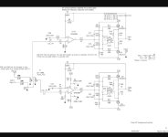
Audionics of Oregon BT-2 Preamplifier Overhaul
- By bazzle592
- Analog Line Level
- 22 Replies
Hello all-
I recently picked up this Audionics of Oregon stack for cheap - a BT-2 preamplifier with a PZ3 Series II amplifier.

They were sold as-is, and upon testing, I found the preamp to sound very good, but it exhibits the classic snap-crackle-pop-fizz of failing silicon.
The folks at Audionics decided to pot the circuit boards, presumably to protect their IP. Unfortunately, this made them absolutely impossible to service. They were violating right to repair way before it was cool!


I tried replacing the two small signal transistors that weren't potted, but they didn't have any effect. Based off of the 8-pin packages visible from the bottom, this looks like a simple op-amp based line amplifier to me. Even if I could service the board, finding these ancient op-amps would be a tall order in itself.
I love the simplicity and weight of the chassis, and the switches/pots are of very high quality, so I would like to revive this preamp by installing modern boards.
What are some favorite DIY preamp boards of the forum? I think I would like to keep it op-amp based to keep in the spirit of the original circuitry, but am open to discrete ideas as well. I want to buy boards in kit or pre-assembled form, not looking to break out the proto board this time. I don't mind buying PCBs and parts separately though.
I would like to replace both the line and phono boards, so suggestions for both are welcome.
Thanks!
I recently picked up this Audionics of Oregon stack for cheap - a BT-2 preamplifier with a PZ3 Series II amplifier.
They were sold as-is, and upon testing, I found the preamp to sound very good, but it exhibits the classic snap-crackle-pop-fizz of failing silicon.
The folks at Audionics decided to pot the circuit boards, presumably to protect their IP. Unfortunately, this made them absolutely impossible to service. They were violating right to repair way before it was cool!
I tried replacing the two small signal transistors that weren't potted, but they didn't have any effect. Based off of the 8-pin packages visible from the bottom, this looks like a simple op-amp based line amplifier to me. Even if I could service the board, finding these ancient op-amps would be a tall order in itself.
I love the simplicity and weight of the chassis, and the switches/pots are of very high quality, so I would like to revive this preamp by installing modern boards.
What are some favorite DIY preamp boards of the forum? I think I would like to keep it op-amp based to keep in the spirit of the original circuitry, but am open to discrete ideas as well. I want to buy boards in kit or pre-assembled form, not looking to break out the proto board this time. I don't mind buying PCBs and parts separately though.
I would like to replace both the line and phono boards, so suggestions for both are welcome.
Thanks!
winding air coil inductors - removing springiness?
- By Sadface
- Construction Tips
- 14 Replies
G'day Guys,
I am winding some inductors for the output thiel network on an amplifier:
5uH.
I've gone with 18awg wire. According to this calculator https://www.circuits.dk/calculator_single_layer_aircore.htm
I need 18 turns on a 25mm mandrel.
After winding the copper wire around my mandrel (a 25mm electrolytic capacitor) the wire wants to 'spring' back and loosen up.
Any suggestions on how to get the thing to hold its form nicely so that I can dip it into some epoxy?
problems with REW measurements - suspected amplifier malfunction
- By arivel
- Equipment & Tools
- 3 Replies
Hi everyone .
So far I have used the equipment listed below to take measurements of my Karlson K12 prototype kabinet. I have always used a single speaker (12" woofer) without crossover and without tweeter, sweep frequency 20-2KHz:
Laptop PC combined with REW software, e-mu 0404 sound card, om1 line microphone and finally marantz pm510dc amplifier.
Lately I haven't been able to take measurements anymore and I would like some help to understand where the problem lies.
when I start a measurement, REW detects no signal, or very low signal, as you can see from the attached image. Despite this, I hear a very loud noise coming out of the speaker. I suspect the amplifier is the cause but I can't be sure.
I tried listening to music but what I hear is unpleasant. when everything worked well I always took the measurements with the amplifier's EQ active but with all the levers set to zero. now I can no longer use this function and it has been disabled with the (EQ defeat) button because otherwise a horrible noise will be heard. lately you can't even hear the noise anymore but a protection is triggered (I imagine this) and you can't hear anything.
there is another thing that I don't understand, REW doesn't work right even though the sweep volume is high. perhaps some protection is triggered within the software because what comes from the microphone is wrong. I suspect the problem lies in the amplifier's EQ circuit.
what do you suggest?. Hello and thanks
Attachments
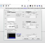
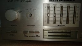

Broken tubes
- By drewan
- Everything Else
- 3 Replies
Hi, I'm on the scrounge for non-working but otherwise intact tubes for some steampunk artwork, obviously I'll pay for P&P. Many thanks..Methinks this is only for UK members.
🙂
🙂
Can someone identify this driver?
- By swingarm63
- PA Systems
- 14 Replies
These are for sale locally and it's not clear what make these 15" speakers are. Hoping someone here might know.
Thanks
Thanks
Attachments
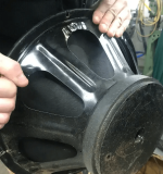
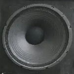
Mitchell & Johnson power amp schematic?
- By Sarchi
- Solid State
- 10 Replies
I have an M&J S815 power amp, working fine, but since they're out of business with no contact info, can anyone help me locate a schematic? I've talked to the local importer and they had no info.

Is this a gimmick?
- Multi-Way
- 45 Replies
Scanspeak came out with these. It’s hard to believe that an oval voice coil would have less distortion than a round one does. I guess that’s why they aren’t showing distortion specs. Distortion probably sells fewer speakers than style does. I have no doubt they have low distortion, but how much does the voice coil shape matter?

A little tube porn: "Gossamer" VT-62 (RAF) SE A2 amp
- By pmillett
- Tubes / Valves
- 11 Replies
Finally built some amps using the VT-62 (RAF) triode (basically 4304CB or DET12, or 834 with a B4 base). Conservatively about 15 watts out. Hot as heck.
Driver is a triode/pentode with the pentode a DC coupled cathode follower to drive the VT-62.
Details at http://www.pmillett.com/gossamer.html

Driver is a triode/pentode with the pentode a DC coupled cathode follower to drive the VT-62.
Details at http://www.pmillett.com/gossamer.html
Curve tracer suggestions
- By HgRectifier
- Tubes / Valves
- 78 Replies
Good morning tube amateurs, I'm looking for curve tracer hardware design suitable for connection to external oscilloscope, in order to perform measurement on sweep tubes such as the marvelous posted in #1413 dated 2021-02-14 (page 71 of "Those Magnificent Television Tubes"). Any suggestion for schematics or second hand equipment? Something equivalent to Tektronix 570 but with external oscilloscope. Thank you
Turntable/phono stage grounding issue
- By K-hole
- Analogue Source
- 9 Replies
Hello!
I can't seem to ground my turntable to the cairn boost phono stage without attaching the GND to one of the phono inputs. It massively reduces the hum but it doesn't entirely get rid of it (hum is only audible when there's no music and I turn it up a bit but it's still there in the background).
Any idea why the original GND isn't working? I've opened it up and the connection from the terminal to the board is fine.
Could it be that there is no earth wire on the kettle lead I'm using? It's not the original one as I bought it second hand and the lead is moulded so I can't check without cutting the wire.
Also is there any danger of damage to anything by connecting to the phono?
If I connect it to the GND on my old tuner it's similar to attaching it to the phono, perhaps a tiny bit less hum...could it be an issue with the deck itself?
Thanks in advance.
Tokin THF-51S Pairs NOS
SOLD !
New unused Tokin THF-51s "Precisely" matched pairs (2pcs) with curve traces that I purchased from Tomoaki Watanabe recently. Still have 1 pair available. Watanabe is now fet-tokyo on ebay
$200./pair with Free shipping (US 48 only)


New unused Tokin THF-51s "Precisely" matched pairs (2pcs) with curve traces that I purchased from Tomoaki Watanabe recently. Still have 1 pair available. Watanabe is now fet-tokyo on ebay
$200./pair with Free shipping (US 48 only)
Longest songs
In this era of instant gratification 128 character posts and 2 minute noises that passes by "music"... you listen and enjoy long songs?
I mean, songs that are significantly longer than 10 minutes ( often studio songs will offer much longer versions in the Live versions, which I think are superior ).
I'll give you some rock songs ( classical doesn't count because by definition it's always long format ).
Pink Floyd, Echoes.
The Allman Brothers, Mountain Jam
The Doors, Celebration of the Lizard - Live
Sure, the Grateful Dead have a lot of loong songs... but most of them were "recorded" as live shows... not studio albums.
IMHO, a good long song must tell a story... take you into a real mental "trip"... bringing you up, keeping you up there and then bring you down gently...
Leaving Thumbs Up?
- By speaker
- Forum Problems & Feedback
- 4 Replies
I see no icon and I do not have any script or site blocking on. Any ideas why this is?
Load more
Projects by fanatics, for fanatics
Get answers and advice for everyone wanting to learn the art of audio.
Join the Community
507,714
Members
7,885,594
Messages