tool to expand female RCA terminals?

Greetings everyone. I friend of a friend gave me a pair of 1.5M RCA Interconnects from a company called Harmonic Tech. I went to use them and found that the female RCA connector is too tight to fit onto any of my male connectors, I tried several different pieces of audio gear. The female ends are so small, I do not think putting dielectric grease on will help, and I fear that I will end up pulling the male RCA's off my equipment when I go to remove the interconnect cables.

I contacted the company and they are no help at all, want me to buy a new set of female RCA's for $200 and mount them myself.

So my question to all of you is this: is there a tool or method to expand the female RCA terminals so that they will fit onto standard sized male RCA ends? I have tried inserting one female end into another, that is, using the center positive part to try and expand the gap between the center post and the outer part, but that did not help.

Thank you for your help.

Adcom GFA565

I know this has been discussed many times, the amp is blowing dc rail fuses. I've gone as far as I can with my diagnosis,all of which I have learned here, mostly by reading and rereading cogeniac and anatechs posts, #203 ,207etc. I own a variac and a fluke volt meter. So far ,after jumping the soft start resistor I can hear the relay clicking in. The amp and the variac buzz at about 15 volts, dead short somewhere. When the rail fuses are removed the amp powers up to 110 volts, no magic smoke. If I put either rail fuse in the amp powers up ok,as long as iI put only one fuse in at a time, doesn't matter which side.. fuses in power lines to rails disconnected (post 186) powers on to 110 volts.points 3,4 on output board disconnected , everythig else connected amp powers on to 110 volts.could both sides be biasing at once?. The factory leaky board caps were replaced 15 years ago wit nichicons. I'm hoping the board is bad, as I'll buy a new one from chris hoppe. I don't know where to go from here. When the amp failed it didn't take out my speaker,nor did it pop when turned on or off.

For Sale Harman Kardon Citation II amplifier - $2400 shipped

Here's a nice plug-&-play Harman Kardon Citation II amplifier with full rebuild. All original chassis paint and gold silkscreen lettering intact. Some paint missing from the transformers. Light scuffing on the faceplate. Visually a very presentable and clean amp.
Wired as-original in Ultralinear mode for full power.

Known history: I received this as part of a trade, non-functional. Only ~80% of the rebuild was complete at the time. I ordered a few parts from Jim McShane and finished the work needed, with some long-distance help from Chris Rice. Voltages were verified and then music tested in main system for a week.

*Rebuild includes:
  • Jim McShane Level II upgrade kit
  • '2-A' coupling cap kit (Russian K40Y PIO and Solen film)
  • '2-S' small value cap kit (RelCap film and silver mica)
  • premium resistor kit (Dale wirewound)
  • bias current modification (replace 15 ohm resistor with 18 ohm; to reduce current & retain correct "bias" mark reading)
  • (4) Micalex octal sockets with ground tabs
  • (6) Belton 9-pin sockets
  • (1 Set) gold RCA jacks
  • (1 set) OEM type speaker terminals
  • (6) GE JAN-12BY7A tubes

Other details:
  • new faceplate / bottom cover
  • new chassis feet set w/ hardware (larger than original / rubber)
  • new AC line cord, 3-prong
  • ON/OFF power switch added
  • power tubes installed;
(3) TAD KT88-STR
(1) Gold Lion KT-88
- extra tubes included;
(1) GE JAN-12BY7A
(1) GE 12BY7A

SOLD! $2400 shipped CONUS, fully insured, all fees included
(discount for local pick-up in 89147)

> Click here for more photos <

P1080322.JPG

Attachments

  • P1080324.JPG
    P1080324.JPG
    325.7 KB · Views: 100
  • P1080327.JPG
    P1080327.JPG
    340.4 KB · Views: 85
  • P1080338.JPG
    P1080338.JPG
    304.2 KB · Views: 86
  • P1080335.JPG
    P1080335.JPG
    342.6 KB · Views: 105
  • P1080350.JPG
    P1080350.JPG
    564.9 KB · Views: 111
  • P1080352.JPG
    P1080352.JPG
    424 KB · Views: 123
  • P1080342.JPG
    P1080342.JPG
    522.2 KB · Views: 110
  • P1080333.JPG
    P1080333.JPG
    398.4 KB · Views: 95
  • P1080356.JPG
    P1080356.JPG
    257.7 KB · Views: 92
  • Like
Reactions: ranshdow and adason

Hello World from Denver

I’m poking my head in here because I’m considering some wacky ideas, lol.

I’m a old bass player who is just now grabbing a bass again after decades. I’ve always been an experimenter and it still hasn’t changed, lol.

I want to make a bass case that’s also an amplified cabinet of a sort. The new class D amps are so small and efficient I think it’s just possible to make something “Jam worthy” in such a fashion.

I’m looking at audio exciters to actually make the entire front and back surfaces of the case into speakers, with maybe an 8” sub (or 6x9 or 6.5 or…. Whatever will stuff) using the case itself as an enclosure to fill in the bottom end some. (Low b fundamentals are 31.5 hz)

Then, ideally I could also run it from DC using batteries (custom pack or 18v Ryobi?) at maybe lower output or plug in for max carnage.

Anyway, I need to do more specific research and this forum seemed like the place to look.

Thanks in advance for your patience with my incessant questions, lol.

Troy
  • Like
Reactions: Jason

Intro - from USA

Hello, I'm now a retiree from computer engineering. I've built Zaph Audio 2.5's, Solstice, and CSS Towers. I have a table saw and can make cabinets! I have restored a big pair of Polk SDA's (the big ones) from 1985 and love them. I have a Parasound Halo A21 amp, McInstosh MC2105, Threshold, a Class D Buckeye, and an Akitika which I build from his kit. I also do veneering. My wife is from Ukraine and one of my best friends is from Bulgaria. I love Slovenia if I could pick a place. I'm using a Gustard R26 as a DAC. Trying to build a streamer with a Raspberry and a board. I also shoot long range competition.

Scope Design: JFET Input EXICON Output 10 Watt Class A

The name of this amplifier is EXIAMP10.
Because the output devices are EXICON transistors and the target power is 10 Watt Class A.
The input is a quality JFET: LSK170.

I will test this amplifier in simulation. Also use a simulation oscilloscope.
AC Analysis and Fourier Analysis are also possible.

Post #85 and further there is a PCB.

Scope Design JFET_13.jpg

AMB M3 headphone amp

Hello Everyone,

I am selling my AMB M3 build which has served me well throughout the years. It is the standard three-channel build outlined on the website (link) with the following specs:
  • Enclosed in a hifi2000 Galaxy Maggiorato anodized full aluminum casing
  • Analog Devices AD8610ARZ OPAMP for all three channels
  • OPAMP bias current set to 5mA, MOSFET bias to 80mA (can be set with trimpots), gain to 11
  • 24V AMB Sigma11 power supply with custom current regulator diode equivalent circuits
  • Extra large 2.5" heatsinks (originally I wanted to use it also as a small speaker amp)
  • Custom PCBs for the volume, and for the LEDs around it (green and red LEDs, red was supposed to be for speaker output). The ring around the volume knob lights up.
  • The audio input and output cables are pure silver (see the pics).

The amplifier sounds very well, so well, that I designed a fully differential headphone amp based on it. This is the only reason why I am selling.

I am located in Princeton, NJ for local pickup and I could ship it anywhere to CONUS. I prefer payment with PayPal or cash.

Price: 350USD + paypal + shipping

Let me know if you have questions!

Cheers!

Attachments

  • IMG_20240529_225902.jpg
    IMG_20240529_225902.jpg
    120.7 KB · Views: 134
  • IMG_20240529_221550.jpg
    IMG_20240529_221550.jpg
    173.8 KB · Views: 133
  • IMG_20240529_220944.jpg
    IMG_20240529_220944.jpg
    277.1 KB · Views: 133
  • IMG_20240529_220919.jpg
    IMG_20240529_220919.jpg
    502.2 KB · Views: 156
  • IMG_20240529_220928.jpg
    IMG_20240529_220928.jpg
    381.7 KB · Views: 141
  • IMG_20240529_220951.jpg
    IMG_20240529_220951.jpg
    238 KB · Views: 132
  • IMG_20240529_220956.jpg
    IMG_20240529_220956.jpg
    200.7 KB · Views: 109
  • IMG_20240529_221003.jpg
    IMG_20240529_221003.jpg
    293.9 KB · Views: 135

About an Onkyo T-4970 tuner

Hi to everybody, 🙂

I just found an Onkyo tuner T-4970. It's from the 92-95 years, and it's pretty good, it was not far from the very top Onkyo tuners.

I have a few questions about it :

- On the main board there's a heat mark (a brown area) under the resistors R904 (3W) and R905 (2W). Can it be normal ?

- There are few OPA in this tuner :
NJM4560D
NJM4560D-X
NJM4558D-X
and I think we can find better now. Can I replace some of them with newer, better ICs, but without changing the component values? I have tools to measure electrical values, but RF is another world... (I have some BB OPA2604AP in my drawer)

- Final thought, are there any capacitors in the signal path worth changing for better ones? Almost all capacitors in this tuner are Sanyo, not Nichicon or Elna...

This is also a message for SinGun especially, I could read he owns this tuner, he likes it and he tweaked it too 😉
The service manual can be found here :
https://archive.org/details/manual_T4970_SM_ONKYO_EN
Thank you, have a nice week-end ! 🙂

Attachments

  • T4970_ONKYO.jpg
    T4970_ONKYO.jpg
    559.3 KB · Views: 154

An excellent source for Metric Fasteners

My client and I decided that the stainless steel machine screws that were holding the Beyma AMT's faceplate on, in low-light conditions, looked like cat's eyes staring at you. Rather than painting them with a paint marker, I went in search of black metal replacements.

One supplier had a minimum quantity of... 500 pieces. Many wanted a 100-piece order. A couple wanted a 50-piece order. There was only one supplier that had no minimum quantity (but there was a $5 order minimum before Shipping). Photo is of Black Stainless Steel.

IMG_0794 copy.JPG


So, if you need metric fasteners, and don't want to buy 50 pieces, Belmetric is the answer.

john
  • Like
Reactions: dliscomb

Assistance with transformer on Carver TDR 2400 dexk

Greetings,
I purchased a near mint deck that doesnt power up. Although the label at the back says 220V it had a US plug (I am in UK 240v). Seller said it was to plug to other equipment inlet.
There is no power and checked transformer with DMM and had no voltage on secondary. The primary side on the 0-110-220 pins had no resistance between 0 and 220 so my assumption is an open thermal fuse. With no visible bulge on the transformer, I opened the plastic cap of the trafo and in between 0 and 110 there was a point of a winding which my assumption is that its the side after the fuse. I soldered a wire and plugged it in and now I get 24-0-24 on secondary side.
Does it mean that it works and I just bypassed the burned fuse? Should I connect it to the deck to troubleshoot further?

The deck doesnt seem to have any obvious damage to the circuit other than a burnt icp-n25 fuse after the secondary.

Many thanks for any help

Attachments

  • PXL_20240610_121616977~2.jpg
    PXL_20240610_121616977~2.jpg
    283.6 KB · Views: 61
  • PXL_20240610_114512835.jpg
    PXL_20240610_114512835.jpg
    348.4 KB · Views: 59
  • PXL_20240610_114451845.jpg
    PXL_20240610_114451845.jpg
    343.4 KB · Views: 45
  • PXL_20240610_114442230.jpg
    PXL_20240610_114442230.jpg
    351.6 KB · Views: 55

ESS Heil AMT-1 Defect?

I just received a pair of brand new Heil AMT-1 from ESS Labs, but on one of them, I noticed a strange defect(?). It appears almost as if somebody marked an "X" with sharpie/marker on the flat diaphragm before it was folded. I'm sure it functions fine but a bit concerned about resale value. So far no reply to my email and no answer on the phone. Anyone else ever see this sort of thing?

0530241908.jpg

Troubleshooting a selective hum

This is somewhat me circling back to an issue I was having months ago. I've been working on a Marantz 1200 on and off for a quite some time. I'm convinced its possessed by the previous owner at this point...

The issue:
-Ground loop-ish hum on the right channel only (next to the transformer)
-Only when the selector is set to "System 1" or "System 2" (Not when set to "Both")

Remediation:
-Changed the filter caps as some have suggested
-Changed the output transistors (in case it was actually oscillation)
-Biased to 14 mv across bases
-DC offset in sub mv range

Notes:
-Was a 120Hz (mostly) square wave with some higher frequency noise on top.
-Bias adjustment did have some influence on the intensity of the hum
-Adjusting bias on left channel has significant influence on hum in right channel (Why??)
-When in my garage, Simply connecting my DMM to the base leads was able to eliminate the hum (prior to transistor swap)
-It is now only occurring in my room, not in my garage (makes it real fun to troubleshoot)
-Prior to filter cap swap, it was always audible through headphones. (weather set to Phones only/System 1/System 2/Both)
-Prior to the transistor swap, it was occurring in my garage, AND in my room
-Connecting the common ground screw on the back of the amp to earth ground in my room does NOT influence the hum (I thought it might)

I'm at a loss, and any help would be appreciated... Thanks yall!

Philips speaker kits vintage

Dutch Philips company had very popular loudspeaker kits in 1960-70s. They produced drivers for all purposes and were active in developing eg. dome tweeters. http://www.troelsgravesen.dk/WWDT.htm

My Philips AD2525 kit from 1972 - 50th Anniversary

My diy hifi started at age of 12 with this speaker! Actually this one is the second speaker I assembled in 1974, to make a stereo pair. I used them until 1988 at my parent's house in my room, in corners. I had to set bass level to max, and now I know why. I have had them stored since, but now I'll get rid of them! I made bigger 3-way kit speakers for my own apartment in 1882, which are now at my son's apartment! DiY hobby re-incarnated around 2007, after busy family years.

Please, tell about your own Phips kit memories in this thread!

More pictures and measurements here https://photos.app.goo.gl/7SpdVrRZknaJF9Ah8

Attachments

  • Philips 1.jpg
    Philips 1.jpg
    443.8 KB · Views: 1,637
  • ADkit onax near WMT 200ms ERB.jpg
    ADkit onax near WMT 200ms ERB.jpg
    184.1 KB · Views: 485

Should Floorstanders really stand on the floor ? or on a plinth, slab … Is tweeter height the main factor to consider.

I use WD25TEx closed boxes - and have them on marble slabs as plinths. I don’t really like the “ imperial”look and am thinking of making some wooden stands. but is tweeter/ears height the deciding factor ? or would an open space between them and the floor perhaps have an effect? I saw some stands designed by Planet10 in a sort of inclined sling arrangement in a thread on A25/deVore clones- worth trying ?

Low mid to go underneath Unity Horn

I have four 12NDL88 drivers to put below a unity horn I have designed. My aim is to do 150hz up to around 400hz which is why I have gone for angled baffles to move the acoustic center of the drivers closer together.

I have currently got a port either side to allow for space behind for the 12" driver but I might try and get it to fit with a single port on one side.

I started off by simming in hornresp to get something vaguely what I want.

1716984473328.png
1716984487794.png


I then drew it up and simmed it in Akabak BEM and my output is wildly different, I have checked the volumes and areas a few times. I checked the volume using Akabak by adding everything to the repository then using the meshing to calculate the volume. Some of my triangles are maybe a bit thin but I will redo it sometime, the LEM sim is the same though.

1716984547519.png
1716984570862.png


The impedence nearly matches in both

1716984605966.png
1716984622897.png

I have also drawn it up in LEM in Akabak, without the angled baffles, to compare and got the same results as BEM

1716984664468.png
1716984686173.png


Does anyone know what the reason why the sims are so different? I kinda want to build it and measure it to see how it will do

Western Electric KS13385 vs. Cardas hook up

Hi!
I am rebuilding the 35 years old Tannoy DC2000.

The crossover upgrade by using Jantzen inductors, ROE MKT1822 film cap and Mundorf Ultra resistor.

A new cabinet would be built with composite bamboo.

Now I have a question for you guys. Which wires should I use for the upgrade?

1) Cardas 15.5 AWG all the way or

2) Western Electric KS13385 16 AWG all the way or

3) mixed by using Western Electric KS13385 AWG between the binding post and input of crossover and 6 x Cardas 15.5 AWG wiring from crossover to the drive units.

Please advice

Many thanks!
PS. Actually I also considered the Gotham 16 AWG as input of crossover and Cardas after the XO.

Bought my first rig!

Hi all,
I’ve found a small soundsystem on Facebook market place that I went and bought today! I was hoping for help on the next steps from here…
It’s 2 Fane 15” scoops unloaded (scaled down to 12”)
2 es18 loaded (scaled down to 10”)
And 1 8” midtop with 1” cd horn (need new cones)

My hope is to have it for a small house party/ outdoor system, and so far I think I need to: load remaining speakers, get atleast 4 channels of amps for each different driver, crossover and limiter (which will plug into laptop/decks) and I’m heavily considering buying a 18” hog scoop premade to reinforce bass

I’ve found plans for the scoops and es18 full size, if I can confirm it’s a scaled down version, should I plug these values into hornresp/akabak and see what it gives me? Seller gave me link of what he put in the scoops,(https://www.thomann.de/gb/the_box_speaker_12_280_8_w.htm) and I was thinking any 8” mid woofer with 1” cd will work.
i have a calibrated microphone, so my first step once I’ve verified the speakers are a perfect(ish) scale down is to measure the frequency response of the kicks, and find a suitable driver that goes high enough for the scoops and low enough for the top? Then once I know the limiting spl get amps that will drive all of them to atleast that spl with headroom. I’m also between a rack DSP like an ultra drive or DMX or daisy chaining 2 ADAU1701 together to get 7 out, only problem being it’s unbalanced so length might be an issue
My questions are-
How do I pick the right drivers/ how do I ensure they’re suitable? Is it just a case of plugging different specs into hornresp and akabak till I get a good response?
Will an 18” hog scoop (with pd1850) intergrate with the system well? Is there any way in knowing without picking a driver for the rest of the system?
And is there any parts I’ve forgotten?
If you’ve read this far, Thankyou!
IMG_5443.jpeg

Experience with ACA Mini in parallel mono mode

Hello all.

I was quite satisfied with my two ACA amps in parallel mono mode driving DIY 4 ohm speakers (woofers are double voice coil units wired in parallel). Summer is over up here and I am contemplating again Class A operation for the Winter... I already built an ACA Mini (see photo, below the two ACAs) as a stereo amplifier, but I have another complete kit yet to be built. Before I go ahead and make myself a pair of Mini Monoblocks, I would like to hear from folks who have used their ACA Mini in parallel mono mode. That would certainly help. Cheers!

--Christian


ACAs.jpg

What is wrong with Darlingtons?

Hi to Everyone ! at the cost of sounding tedious i would like to understand more about why darlingtons are so neglected in audio power amps
apart from a few small-scale British designers it is almost impossible to find integrateds or power amplifiers that use darlingtons as output devices
If nothing else they allow you to skip a driver stage, right? thus simplifying the project as a whole
From a completely ignorant point of view they should be a godsend for lovers of minimalism
Not only that I know at least one medium power amp that uses darlington and it sounds pretty good, definitely good actually
These are the Albarry m408 monos which at least in my country Italy had become quite famous after a highly rated reviewer had praised them
Why does everyone avoid them? do they stink maybe? 😵
😉

For Sale Audio Nirvana Super15 Alnico

Sold! To a very pleasant buyer 😉


For sale are 2 Audio Nirvana Super15 Alnico speaker chassis.
I bought them from Dave in 2019. The speakers have been used for 1.5 years and have around 500-600 hours of use. So they've just been played in properly...
The condition is very good. The sound is great, Dave said: "This is the best sounding speaker in the world" 😉
I would like €650 for it. Shipping will be in the original packaging to wherever you want.

2.jpg

Audio Nirvana 15 Alnico.jpg

Capacitors will revival?

May be revival is not a technical word. I don't know! For capacitors (pf or nf), Polypropylene Film (metalized or not) / C0G (NP0) type, or simple seramic/mica are there any revival time. After, using them some after time, perhaps days sound is changing. It's not very simple change. Amplificator is revivaling 🙂
Have you got any idea. Capacitors datasheet doesn't say any revivaling time. thanks,

How to measure just Speaker Cone Resonance? Just the cone without coil

I have come across this way of measuring speaker cone resonance in AES standard. Just the cone without coil or magnet to see what frequency its resonating.

https://www.scribd.com/document/94952543/Aes19-1992-Loudspeaker-Resonance-Measurement-Procedures

Look at one option is to put a subwoofer in a box and then put the cone on one side of the box and excite the subwoofer sweeps be done and wherever the cone which is to be measured displaces more at a particular resonant frequency I guess that would be the actual resonance of the cone. The above AES paper from 1992 is suggesting that.

I saw it on Ciare youtube video as well Login to view embedded media
any inputs from the members would be greatly helpful

  • Locked
MoFi Sourcepoint8 : The $680 Dannyfication - well spend?

Some measurements ... we see a TroubleCone , missing highs and resonant sound!

Login to view embedded media
Of course Holy NoRez from TeXaZ will fix any airborne nastyness 🙂

Still worth to buy?

SBA/Satori 7" Coax might be better ...

Any half-good 3way speaker will rip it apart?

Pros & Cons please - this board is thirsty , water us with your wettest opinions!

Sourcepoint 8 - any good or just another fidelity obscurity? (heaven or hell)

just flying by ..

(don't kill Danny he's only the piano player)

Driver for Array? Visaton SC4.6FL 1.6" x 2.4" Full-Range Speaker

Has anyone used this driver for anything, Visaton SC4.6FL 1.6" x 2.4" Full-Range Speaker?
It appears to have a great frequency response and might be good as a driver for arrays. The downside is the power handling is only 5 watts. I don’t see that as an issue if 24 of them were used in a tower. $12.14 each!

sc4.6fl_8_180815_1.JPG

sc4_6fl_8_fs_180706.gif


Here is a link to PE, but I’m sure you can find these elsewhere. https://www.parts-express.com/Visat...le-Full-Range-Driver-8-Ohm-292-658?quantity=1
  • Like
Reactions: tubelectron

6U10, 6AC10, 6D10, 6AV11 Tubes

Greetings,, Are the above titled tubes, & others like them, interchangeable in the precise sense the 12**7's are swappable with a resulting change in gain? Or is there too much 'other' stuff going on in those compactrons? In particular, My Ampeg
AC-12 calls for a 6U10, as do many, many Ampegs, and I wanted to know if the other Compactrons mentioned are drop in substitutes that may offer different, or more, amounts of gain?
Many Thnx, Kenny ॐ💃🪕

Polystyrene capacitors

Is anyone familiar with NSF polystyrene capacitors? These all seem to have the "KF59" mark on them. I just bought an entire set of those caps, all are 2% tolerance 400V, going as high as 89800 pF, NOS presumably from the 60s-70s. The high voltage application is why I added this topic in the tube section.

Bought them in a lot with Philips mustards caps, and to be honest I'm only interested in those as my hobby is guitar and not Hifi. I'm planning on getting a fair price for the polystyrene caps where buyer is also very happy with, and give it entirely to the lady from which I bought the lot. She inherited it about 20 years ago from her father, and left it untouched in her garage.

Any help would be appreciated. Added some pics to see what I'm dealing with.20240607_214335_copy_1020x765.jpg20240607_214342_copy_1020x765.jpg20240607_214351_copy_1020x765.jpg20240607_214321_copy_1020x765.jpg20240607_214316_copy_1020x765.jpg20240607_214309_copy_1020x765.jpg

Attachments

  • 20240607_214326_copy_1020x765.jpg
    20240607_214326_copy_1020x765.jpg
    270.8 KB · Views: 140
  • 20240607_214330_copy_1020x765.jpg
    20240607_214330_copy_1020x765.jpg
    272.8 KB · Views: 134

Forced air cooling subwoofer driver?

So I've been dabbling with the idea after hearing a sound system recently that definitely used forced air cooling within their subwoofer drivers. So I'm used b&c tbw100 drivers and they have ventilated voice coils, I found an old post regarding cooling drivers using a copper/aluminium plug machines to fit tightly into the pole piece which is something I'm curious about. But also would it be possible to duct air into the drivers around the voice coil to help shift some of the heat actively out in order to lower power compression and push the drivers a little harder. In the keystone cabinets I'm using your limited to 750w aes of the total 1500w, so figured with some active cooling I might be able to eek a little more out of the cabinets!

Recalculate MLTL for Supravox 285 or 215 woofer

Hello,

First of all I would like to introduce myself, my name is Dominic and I'm on this forum since several years. I use to read and learn a lot here but I don't write so much usually since I'm not experienced enough to give advice to anyone 😆.

I would need your help about the building of my new speakers. I wanted to use the TAD 2001 drivers in the simplest design possible, so I decided to replicate a project that I found on the web (french forum), it's a 2way design with tad td2001 drivers on jmlc horns and supravox 285gmf woofers in MLTL enclosure, with Jean-Michel crossover. I don’t know if I can put the link here, but it's easy to find.

My first idea was to use supravox 215 woofers (similar to Cessaro entry level speakers) but I was not able to find an already existing design (including crossovers circuits) so that’s why I ended up with the 285.

Long story short, I don't want to make major changes in the design since I have not enough experience and I don't want to mess with it, I just would like to "adjust" a little bit the shape of the bass enclosure.

Attached the simulation published for the original 150L cabinet (internal 108x40x40), done with a software by Martin J. King (anyone used it?).

My question is: is it possible to reduce the height (around 90cm internal) and in case also the width (around 32cm internal) keeping similar results on the bass extension, maybe increasing the depth to compensate? Or this would spoil the entire MLTL design concept? (It would become a “normal” BR…?)

Can anyone help me recalculate the enclosure with reduced height and width?


If it’s not possible to reduce the height of the box with the supravox 285, maybe it would be possible using the 215 woofers? In that case I would need to recalculate the enclosure and adjust the crossover.


Thank you very much for your help!


Dominic

Attachments

  • Like
Reactions: wchang

Some new buys Garage sale stuff

I picked up a couple today. One pair is a home made set using cheap Jaycar drivers but the other set is some old Tandy
Optimus 5-B / # 40-2006
I hope they are the ones I want with the twin 16R tweeters doing the midrange and a singleton working up higher
Anybody here have any experience with them before I pull the drivers out and check the boxes. One thing tho; these are quite heavy and do appear to be both e=well constructed and in reasonable condition

Attachments

  • IMG_2999.JPG
    IMG_2999.JPG
    101.2 KB · Views: 115
  • IMG_3000.JPG
    IMG_3000.JPG
    85.5 KB · Views: 118

Long time lurker, first time poster

Hi! I'm an audio hobbyist based in NZ, and I'm especially interested in valves & vacuum tubes (both in of themselves, in audio applications, and in totally different applications too!) I've been benefiting from the knowledge in this forum for several years and often find myself here when hunting for information. I'm currently designing an amp all by myself for the first time, so I want to start participating and interacting with this forum and its members rather than just watching from the sidelines!

All of this is a long-winded way of saying hello, so - hi. Looking forward to sharing this passion with you all.
  • Like
Reactions: geraldfryjr

  • Locked
How to improve your AC power

I had tried using inverters and big batteries to make my system sound better.

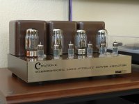
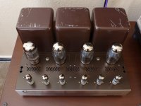
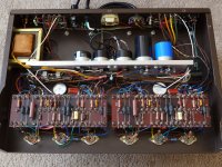
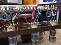
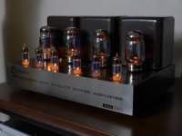
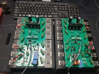
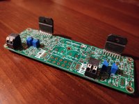
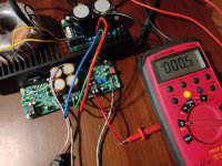
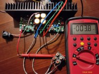
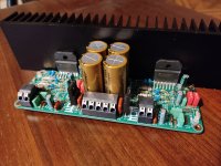
I sincerely think they did work initially but even the GIANDEL rated for 5000 watts inverter could not handle supplying a constant 500 watts total for four THF51 based amplifiers for the two hours I would usually listen. At the end they began to act strangely and make funny sounds so I returned to AC and continued to use the FO-FELIX filters that have been very popular for years in the GROUP BUYS section.

It was obvious that AC from the wall was superior. I do not doubt the inverters had a soft fail. No one wants to buy a new inverter every year.

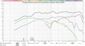
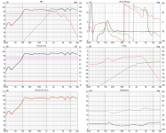
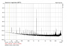
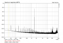
The inverters produced a 22 kHz spike one could see with RTA - though I could not hear such a thing one has to figure it could produce problems at lower frequencies. I could never figure out if the noise emanated from the inverter or the AC wires coming out from it.

In December I took a look at AUDIO ASYLUM, which I do not do very often, and saw a post from a fellow talking about ground boxes and using Rochelle salt to control AC noise. I know the first time I saw an ENTREQ box I laughed as most did. I could never bring myself to pay that kind of money for a box with stuff in it but being a DIYer I would not mind building something and hearing it for myself.

The post directed me to HEAD FI and posts by cdacosta : https://www.head-fi.org/threads/diy-ground-box-thread.968372/

This begins with a basic guide to the ideas presented in the thread.

I bought the Rochelle salt in December and am just getting around to using it. It seemed simple to implement and it is simple to implement.

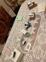
I have treated a bit over half of the switch plates and whatever you call the ones that cover receptacles in my upstairs and can say what this does is extraordinary. It does allow a reduction in noise which is about the only way to explain the far greater level of detail one will hear. cdacosta assures that the more "junctions" are treated the better. He goes into detail about tuning the amount of salt used. I am pleased with using his recommended starting point. I could hear what this does with treating the cover over my system AC receptacle. After that I started installing them in more and more. The subsequent ones do not make anywhere near as large a jump as the first one but there is a cumulative effect. Acosta assures than when his whole regimen in followed one will be amazed at what one can hear. This the combination of the salt packets, ground boxes and wraps around power cables which are all easily made.

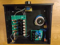
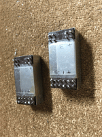
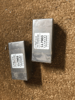
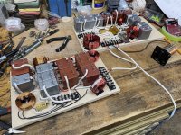
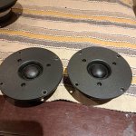
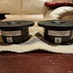
Still waiting for the materials needed for the ground box - the magnetite (the main component) has been delayed. Cannot wait to try this. Starting with two - I use three DACs in my tri-amplified system - the main speaker left and right DACs will get them first.

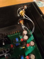
The boxes are easy to assemble - I am using the recipe in the article except for little things like using hide glue I had on hand instead of the stuff recommended.

I figure what this is doing is like good cables - what is revealed could never be revealed by any other method. Some may think it is nothing more than band-aids but I counter what else do we have and we should be grateful for band-aids that work.

I was thinking last night - most of the AC work (I think of Michael Fremer's impressive AC wiring into his listening room) revolves around conductivity - removing obstacles in the path and this is important especially if one uses monstrous amplifiers to drive insensitive speakers which strikes me as wrong but that is another subject - instead of concentrating on radiation. I share with Acosta a suspicion of shielding - of course, if you absolutely need it you have no other choice but to use it - but if you do not absolutely need it it is BAD. So like naturopathic medicine we want to absorb the radiation instead of blocking it - sorry for the awkward analogy but I think it makes sense. Mr. Acosta may very well disagree with all that I have written here. Not to discount a free flow of electrons in any way but the worst aspects of the sound we attribute to our great friend and colleague AC POWER is the radiation that infects everything in its wake.

In my clumsy way I hope I have encouraged the kookiest of you to look into this. As I wrote to my audio friend in Toronto last night, the great Grant Warecki with ears that continue to amaze me, Acosta's concept is valid and important.

Just try the salt packets in a few "junctions" and hear what happens.
  • Like
Reactions: analog_sa

looking for safest way to remove dried tape

I just purchased a 50 year old HK receiver at an estate sale
it looks like for the past 30 years there was tape on the front panel
I was wanting to know how others have removed this tape without damaging the plastic or metal on the front panel. I can think of many ways but not sure which would be safe. I dont want to destroy the finish of the front panel

the picures are samples, there is more than just two pieces to remove

Attachments

  • DSC07275.JPG
    DSC07275.JPG
    248.5 KB · Views: 103
  • DSC07276.JPG
    DSC07276.JPG
    304.3 KB · Views: 77

For Sale TAD drivers and networks for TSM-1

SOLD

Excellent condition drivers:

1 pair of TD-4001 compression drivers.
4 TW-1601a 15" woofers
1 pair cloned TN-1 networks, with charge coupling adding to HF section. Wired with 16ga Silver wire in cotton insulation.

$7500 OBO for the set
TD-4001.jpeg
IMG_9210.jpeg
TSM-1 componentsI.jpeg
IMG_0944.jpeg
IMG_0945.jpeg
IMG_0944.jpeg
IMG_0945.jpeg
IMG_0949.jpeg

Attachments

  • IMG_0948.jpeg
    IMG_0948.jpeg
    217.4 KB · Views: 50
  • IMG_0950.jpeg
    IMG_0950.jpeg
    210.9 KB · Views: 59
  • TN-1 network.jpeg
    TN-1 network.jpeg
    253.3 KB · Views: 59

Schiit DAC one channel fading out

I have an older Schiit Bifrost that's recently started fading the right channel out and then back in. There's no weird noise or cutouts or anything. Just fades out gradually (during a span of 1 to 2 seconds), stays off for a while (15 minutes?) then fades back in.

I've opened it up and don't see anything obvious - no bulging caps or cold solder joints.

Any thoughts as to what the problem may be?

Looking for crossover component guidance my Carrera build

Hi All,

I'm new here and to DIY audio in general. I've only built speakers so far, and from kits at that. However, for my next project I'm building a pair Paul Carmody's Carreras and I'm looking for a little guidance on crossover components.

I haven't had the opportunity to listen to a lot of different components (only Dayton components so far), but I've been looking around and reading a lot of reviews and specs.
I want good components, but nothing overly crazy. I'd like them to feel "price-appropriate" for the drivers. So I landed on spending roughly the same on each crossover as the pair of drivers in the speaker.

For my first form-schematic build, I'd like to choose 1 particular set of capacitors to build the crossovers with. But I have two competing mindsets on the sound I'm looking for. I really like a big soundstage, but I also like a forgiving sound that won't make music that isn't recorded well unlistenable.

Starting with capacitors, after a lot of reading (this one is particularly useful, this one too), I think I'd like to go with 1 of these 2 sets:
My first question is: Has anyone had any experience with either of these sets of caps and what did you think of them? (and if you've used them in a Carrera build or with either of the drivers, I'd really love to hear from you)

Any feedback is welcome.
Cheers!

Bryston B60 - Overview of all Revisions and Series wanted (first launched 1996 or 1997)

Due a large amount of revisions it isn't easy to know concerning individual details, if one find an offer of a device in used condition - thus I want to have a completely overview of various schematics with differences between all released revisions.
The schematic from B60R (Rev.7 from Dec 2002) is just one of many others - so I think.

first release of B60 devices according article from German's magazine image hifi
already in 1997 (go to first attached PDF file) - this means a manufacturing period of at least 10 years according article in "LP" magazine from second pdf attachment.

On the portal from hifiengine are mentioned this three versions of Bryston's B60:
1) without suffix:
https://www.hifiengine.com/manual_library/bryston/b60.shtml
2) "R" (1999-2006)
https://www.hifiengine.com/manual_library/bryston/b60r.shtml
often is mentioned, that "R" stands for RC (i. e. including remote control) and "RP" as before, additional an integrated Phono RIAA unit.
According the images from the offer under
https://www.usaudiomart.com/details/649716630-bryston-b60/images/3164003/
this isn't true. On the main board stands B60R but no motor on potentiometer and no IR receiver for a RC transmitter is inside.
3) "SST" (2004-2006, "C" series, SST stands for "Super Stuart Taylor", a second design of Mr Stuart Taylor - i. e. successor design of "ST")
https://www.hifiengine.com/manual_library/bryston/b60-sst.shtml

under
https://www.audiocircle.com/index.php?topic=90680.0
I read this concerning distinguishing features by serial No:
First B60 #600001
First B60 to use double sided boards – 601350 --- therefore SST Output devices and phono upgrade available.

First B60 to use new outputs – 601733
but under
https://www.audiocircle.com/index.php?topic=8766.0
(go to post #2) I read this: I don't believe there are/were different versions of the B60

reviews
https://www.stereophile.com/content/bryston-b-60r-integrated-amplifier-sam-tellig-october-1998
https://www.themasterswitch.com/review-bryston-b60r
http://www.audioreview.com/product/amplification/integrated-amplifiers/bryston/b-60.html
https://taww.co/post/149987005287/the-not-so-new-newcomer-bryston-b60-integrated
https://www.whathifi.com/bryston/b60r/review

schematic overview
https://web.archive.org/web/20090107033632/http://bryston.com/BrystonSite05/BrystonDocs.html
and
https://web.archive.org/web/20140127050410/http://www.bryston.com/pages/technical.html

brochure
https://bryston.com/wp-content/uploads/2020/02/BP_MPS2_B60_B100_DAC_BROCHURE.pdf

mentioned in diyaudio (no extra thread)
https://www.diyaudio.com/community/threads/building-bryston-amps-from-the-service-manuals.24879/
https://www.diyaudio.com/community/threads/list-of-the-best-sounding-amplifiers.194361/
https://www.diyaudio.com/community/threads/who-is-lazy-cat-and-why-is-his-amps-so-popular.244184/
https://www.diyaudio.com/community/threads/60-100w-mono-class-ab-diy-amps.237281/
https://www.diyaudio.com/community/threads/amplifiers-building-vs-buying.202057/

other threads
https://forum.audiogon.com/discussions/bryston-b60
https://www.audioasylum.com/cgi/vt.mpl?f=amp&m=38623
https://www.audiocircle.com/index.php?topic=60014.0
https://www.audiocircle.com/index.php?topic=90680.0
https://www.audiocircle.com/index.php?topic=88859.0
https://www.audiocircle.com/index.php?topic=143689.0
https://www.audiocircle.com/index.php?topic=32392.0
https://www.audiocircle.com/index.php?topic=108065.0
https://www.ecoustics.com/electronics/forum/home-audio/357109.html

more URLs
https://www.canuckaudiomart.com/details/649273225-bristol-b60da-dac/images/1228323/
https://www.usaudiomart.com/details/649716630-bryston-b60/images/3164003/
https://www.usaudiomart.com/details/649471427-bryston-b60/images/2034793/
https://strangeart.hatenablog.com/entry/2014/05/18/150714
https://www.audio-markt.de/market/bryston-b60r-5650097122
https://www.aussieaudiomart.com/det...-b60r-sst-c-series-with-phono/images/2349757/
https://taww.co/post/164269581582/bryston-b60-cap-upgrades
https://hifi-inside.com/hifi-ht/bryston/integrated-amplifier-8
https://taww.co/post/149987005287/the-not-so-new-newcomer-bryston-b60-integrated (mods)
https://taww.co/post/164269581582/bryston-b60-cap-upgrades (cap upgrade)

Oscillating/motorboating SE EL84 Amp

Hey folks!

Recently bought myself a single ended E80CC/EL84 amp from a fellow enthusiast. First one I've ever had, and I primarily bought it to use with the Beta 8-loaded Dallas horns I'm building (Follow that bit here).

IMG_20240603_001210-01.jpeg


To test the amp I hooked up some of my fathers' cheap logitech satellite speakers. Whatever was there sounded fine, and now knowing it worked I felt confident connecting the Beta 8's just for fun. After a minute or so, I noticed some low-frequency stuff happening and when I looked at the speaker cones they were oscillating something fierce. I cut power and proceeded to sweat bullets. Let it cool down and switched the tubes around, same thing happened. Went ahead and filmed it, oscillations visible only in the last few seconds.

I asked the guy I bought it off of if he'd ever had any issues of the sort, and he told me no. He'd only built it a few months back and had been running it for extended periods regularly through both his BR-mounted Flat 8's and some 3" Tang Band speakers. Upon request he provided the schematics for the amp -- Some sort of DIY kit he had bought off of Ebay. I'll be posting them below.

Only thing about the schematic that worries me is the absence of any kind of resistor on the screen grid, feel like you usually see those on pentode amps. That said, I'm still fairly new to valve amp design so any input from the sages here would be much appreciated.

In the meantime I'm going to borrow some 100x probes from work and feed it with my signal generator to see if I can make any sense of it. Have plenty of old radio drivers that I don't mind bricking for science.

Cheers,
J

DIY work bench/table

My wife has stolen the kitchen table back so I can't make any new boxes.
I need to make myself a new work table.
[ the kitchen table was a bit small anyway]
Before I outlay cash for materials I'm asking what the smallest size table people find useful for making full size boxes is and secondly is there a preference for a ply work top or boards, a sheet of hardwood marine ply is $150- and DAR hardwood in larger sizes for the rails is almost unobtainable just at the moment so I'd need to use pine for those.
Luckily I have 4 large bits of 120*120 spotted gum I can use for the legs

Tamura Transformers and ability to withstand DC

Hi,
I'm building a Differential DAC around a pair (potentially two pairs) of TDA1541 chips. A common choice is to use a Sowter 1465 in the I/V conversion, which can stand some offset DC.

I might try the Sowter regardless, but I was wondering if anyone know whether Tamura input transformers can stand some DC? The datasheets don't specifically mention this, at least not in English 🙂

I'm eyeing a pair of TD-1 or TK-10, but I'm open to advice on that front as well. I'm planning to put an Valve stage behind the transformers so I'm not looking for gain per se.

Thanks!

Matthew

A surprisingly good alternative for the Jordan JX92s...

...is the SB Acoustics SB15NBAC30.
I've been listening to the Jordan JX92s in VTL cabinets daily for well over decade in my bedroom system, I know their strengths and weaknesses.
I was given a pair of the SB15NBAC30-8 a couple of months ago and I build some test cabinets to hear what I'm dealing with, after some "massaging" for a few hours it took me less than three minutes to decide to explore their potential as Full Range drivers.
A number of test cabinets later from 7lt Bass Reflex monitors to 12lt Bass Reflex slim floorstandesr I end up putting them finally in the Jordan VTL as I liked the overall Bass quality of the VTL more.

These sound like the Jordan JX92s on (a double dose of) steroids.
Album after album they never fail to deliver and tracks like "Angel" from "Massive Attack" or "LaHabanera" from "Yello" (which are a definite "no-no" for the JX92s) go up to window and door rattling levels in my small 12sq/mt bedroom without breaking a sweat or loose their composure.

At just 170euros delivered for a pair these are a steal, they are 1/3 the price of the current accepted JX92s alternative, EAD E100HDMKII and 1/5 the price of the ridiculously expensive Jordan Eikona, which I've heard and not impressed, at all.

If you decide to build a pair, depending on your room size, speaker placement and preference you might want to add a Baffle Step Compensation Circuit, details below are for VTL 30cm baffle width (380Hz).

Attachments

  • 20240514_154825.jpg
    20240514_154825.jpg
    270.9 KB · Views: 245
  • 20240514_154702.jpg
    20240514_154702.jpg
    221.7 KB · Views: 245
  • 97747578d7515f236c04c099f88683f4.png
    97747578d7515f236c04c099f88683f4.png
    3.9 KB · Views: 234

Lab instruments _ analog vs digital

Hi sorry for the maybe infantile kind question
Being in love with lab testing at some point in the future I would like to start my own measurements
At present I have a question
Let's take a signal generator or a scope as examples
The main offer is of digital units
Still on YouTube I see many experts using old analog generators and scopes etc.
My guess is that they are somewhat obsolete ?
If I am right why people are still using them?

My guess however it's been proven wrong at least in one case
A totl Audio Precision analyzer has a analogue sine generator slightly less in THD plus noise than the digital one. It has both options
At present I see two options viable for amateurs
A standalone Signal generator plus USB audio ADC like the e1a ADC or a complete USB audio analyzer like the wonderful qa403
Any advice/suggestion will be very welcome and much appreciated
Thank you very much to All of you
Have a nice day
Gino

WD25TEx

My speakers are these Peter Comeau towers. Loosely described as "aperiodics" brecause they were originally inspired by the Dynaco A25 but inside a sealed box/bubble consisting basically of two compartments, both sealed to the exterior with a communicating "aperiodic port between them. So presumably any woofer movements are limited first by compression of the air in compartment 1, thanks to to the "stiff" port and then also by the resistance to be compressed of thevolume of air in the 2nd compartment.
I have no desire to understand what´s happening but in practise the woofers are virtually motionless (1mm at most) during all sorts of music beit Reggae or symphonic so how can it produce any bass at all ?
Just wondering if a 2nd resistive port say in the base of the towers could help the bass go lower.

Question 2 : Given its importance Is there a practical way to check that my towers are indeed sealed around the drivers - I used draught excluder to make up my gaskets for the drivers. Should I reinforce these with a sealant of any sort ?

Noisy USB outlet? Request for testing help.

Hello! I know this isnt exactly related to audio design. But I do hear a high pitched sound coming from my outlets.

I recently remodeled a home and upgraded to USB style 115v outlet receptacles.

However now I hear a faint high pitched hum in the house. My thoughts are that inferior parts are causing "noisy" outlets.

Also the faceplace color and outlet color was noticeably different, both are labeled as white and they both came in the same package. This is just a visual annoyance and not an issue.

So in the spirit of finding a quality USB outlet. I purchased about 9 samples from Amazon.

I removed the 4 screws from the back of the receptacle to expose the insides. However I have no idea what I'm looking at from there. Some are noticeably more complicated than others.

Anyone here interested in testing these? A simple Google sheet would be helpful in finding the true winner.

The goal is to test basic functionality of the unit. (Rated Voltage, Actual Voltage, EMF Emittance, General Quality Of Parts Used, Functionality with two USB devices plugged in, If device is emitting high pitched noises)

Please let me know if you are interested! I can mail these unit and we can test!


Thank you

Attachments

  • IMG_2426.jpg
    IMG_2426.jpg
    121.7 KB · Views: 72

For Sale Toshiba 2SA970BL/2SC2240BL

I have for sale 100 pairs of 2SA970BL / 2SC 2240BL.

Min 10 pairs.

2SA970BL I can sell separately. Price is dependent on numbers. Please enquire with your needs.

2SA/2SC - $5/ pair. Shipping at cost.

R

Attachments

  • IMG_0951.jpeg
    IMG_0951.jpeg
    405.1 KB · Views: 93
  • IMG_0952.jpeg
    IMG_0952.jpeg
    649.7 KB · Views: 89
  • IMG_0955.jpeg
    IMG_0955.jpeg
    235.6 KB · Views: 72
  • IMG_0954.jpeg
    IMG_0954.jpeg
    239.3 KB · Views: 76
  • IMG_0953.jpeg
    IMG_0953.jpeg
    393.3 KB · Views: 78
  • IMG_0956.jpeg
    IMG_0956.jpeg
    283.9 KB · Views: 101

The Chill-baffle3 speaker page

Hi Folks.

I just finalized a webpage to describe my latest three-way open baffle speaker, see:
https://www.fedde.nu/audio/chill-baffle3.html

Stereo.jpg


It uses an 15" daudio woofer, 6" 18 sounds 6ND430 mid driver and ESS AMT tweeter (aka "Heil AMT") with Harsch XO and Hypex Fusion 253 plate amps. More details on the webpage.

For Sale EL156 Telefunken (lot of 8)

[SOLD]

Hello,

I have a lot of 6 EL156 Telefunken, 4 are NIB and 2 used (without the box). Scroll down for pics. Specifically:
  • a pair of NIB EL156 Telefunken, same production batch from 1981. Boxes in excellent condition. 350 EUR for the pair.
  • a pair of NIB EL156 Telefunken, close production batches from 1980. One box missing the flap. 250 EUR for the pair.
  • a pair of USED EL156 Telefunken. Serigraphy slight different between two samples. 75 EUR per unit.
Or… 600 EUR for the entire lot.

12 EUR shipping to Europe / 18 EUR shipping worldwide. All registered with tracking number.

I will accept returns within 15 days under the following 2 basic conditions: they come back in the same electrical and cosmetic condition as they were sent, and 2) shipping costs are not reimbursed.

Cheers!

[SOLD]

crossover phase and some more questions

Hello, dear friends!
I'm designing a crossover for an active speaker on a tda7294 chip. The frequency response and impedance curve completely suit me. However, I don't have enough knowledge to evaluate the phase. Please check it. Do I need to make any adjustments to the diagram?
And a few more questions:
1) Will a polypropylene capacitor of type X2 (snubber type) have advantages over a conventional mylar capacitor in position C4?
2) How much worse would it be to use 2 electrolytic capacitors, anode to anode, in position C3 compared to Mylar?
3) I can't figure out the resistor power dissipation graph in VituixCAD. With the "flat" option I need 5W. When estimating "m-noise" no more than 2W. What to choose?
Thank you very much!

Attachments

  • new_custom_2way Six-pack.png
    new_custom_2way Six-pack.png
    32.9 KB · Views: 93
  • new_custom_2way XO-schema-1.png
    new_custom_2way XO-schema-1.png
    6.2 KB · Views: 88
  • flat.png
    flat.png
    7.4 KB · Views: 84
  • m-noise.png
    m-noise.png
    5.3 KB · Views: 93

4 woofers crossover, is this sound?

I am working on a open baffle speaker with four 10" woofers. I want all four to play low and only one to dip into the upper bass. (I am sure there is a technical term for this). I couldn't find anything online after a long search....only examples with two or three drivers. I want 4 drivers series/parallel or parallel series.

I don't know a whole lot about crossovers but I managed to cook something up. If it could work I will order some parts and try it out.

Could this work? Is there a better solution?
1000000916.jpg


Also, C1 will be quite a high value...what kind of capacitor (possibly with a higher quality bypass cap) would work in this position?

Thanks

A new Line Source HT mains project begins!

Hey all. So got a request to do a custom build for a client/friend who just purchased an 85” flat screen to use as the center of thier combined living/media space. Their desire is for minimalism and symmetry and no center channel!!!…..other than that, I have free reign.

I would have gone in wall for sure until seeing the space and the wall is brick! So much for that! 💩

Well….on wall it will be and I’ve just finished some prelim and came up with a shallow on wall sealed line source for on either side of the screen.
We’ll use 10 Dayton ND 91’s for this 5 groups of two with each group wired in series and all 5 wired in parallel. For tweeters, we’ll use 20 of the Dayton ND20FB domes. I’m not sure how low I can go with 20 of these and not hit any audible distortion on dynamic peaks though…..ideally a 2k cross would nearly eliminate most lobing but only measuring will tell. Off axis response is as good as it gets out to 10k and with the ND woofers, I’m looking at a prelim of 80hz-12khz at flat out to +/-45 degrees so this ’might’ just work out for a phantom center system with just a wee bit of tow in….maybe a baffle angled inwards 5 degrees or so.

The plan is for these to butt up right against the edge of the screen so the screen will act as a continuation of the baffle reducing diffraction and aiding in baffle step. The little ND tweeters if placed inboard should handle the job……the needed low crossover for a true line source is the head ache….the distance between the woofers dictates a cross at no more than 2k to really sum up.

Sub woofage will be handled by an existing pair of Klipsch 12’s they already have placed in the two front corners and the Klipsch on wall surrounds will save……both the center and horn loaded Klipsch towers go bye bye along with the entertainment center the TV sits on……it will go to a wall mount.

So for those that see anything with the driver or design choices I’ve Made, feel free. Depth of the speaker is constrained to 5” which is equal to the TV profile mounted on the wall. Width?…..well….the minimalist thing kinda dictates the obvious……for visual balance, I’m thinking 8” wide max……that will give me enough internal volume sealed to hit a target F3 of 70hz and enough out board baffle to chamfer to meet the wall while minimalizing diffraction…..I hope.

Best woofer and tweeter for ATC SM75-150

Hi.
First post here. Not so new to DIY but new in the forum.
Already partially discussed but that was some long time ago and may need an update. I have purchased a pair of SM75-150, willing to pair with a woofer and tweeter. I am targeting around 100l. Will be built with minidsp, active crossover to 3 amps. Purifi for the woofer and 2x Sabaj a30a for mid and tweeter.
Design is ported.
Similar to a SMC100 ATC, a clone.

My candidates for the woofer are:
- ATC SB75-314 I can purchase from a dealer in Canada (fs 21Hz, Qts 0.24 and Vas of 360l)
- Scan Speak 32w/8878t01 (fs 19Hz, Qts 0.33 and Vas of 234l)

The Scan Speak is a little bit more expensive but is better on paper and can go lower in a 100l box. The ATC seems to be the original design but some say not so deep. The Scanspeak seems to be a beast and very very good woofer. ATC is also excellent I suppose.
Any recommendation?

On the tweeter, candidates are (with more or less integrated waveguide):
  • T25CF001 Seas excel, same as previously used by ATC. Can get a pair used.
  • Scanspeak D2905/990000 Revelator. Doesn't seem to be widely used. I don't see a lot of reviews but one of the few scanspeaks with waveguide.
Other good candidates? Morel?

Crossover points will be 380Hz and around 3000/3800Hz. Some say the mid can go up to 3800Hz, others say maximum 3000Hz. ATC goes up to 3800Hz.

I am interested in your feedback, recommendations. Thank you ! Louis

SEAS 27TFFC c/w Visaton WG148R Waveguide & Other Speaker Drivers

I have some NEW & used drivers for sale:

SOLD******2 NEW SEAS 27TFFC 1" Some Dome Tweeters (currently attached to the Waveguides below) ****SOLD

2 NEW 6" Visaton WG148R Waveguides - $39 USD per pair with Free Shipping

USED Drivers below:
2 Peerless (Vifa) 27TG35-06 1" Soft Dome Tweeters - $49 USD per pair
with Visaton WG-148R - $79 USD with Free Shipping


1 Mission "Super 770" - SEAS P21WO-11 8" Woofer - $25 USD for one
1 Mission "Argonaut 1F II" - SEAS P21WN-15 8" Woofer - $25 USD for one
1 Boston Acoustics 8" DVC (Sub) Woofer - $10 USD for one
2 Mission 770 Woofer Trim Rings - $5 USD for the pair

Take ALL above (NEW & USED) for $109 USD with FREE Shipping to Canada & US
Paypal in US & Canada and e-Transfer in Canada

Attachments

  • 20240605_224848.jpg
    20240605_224848.jpg
    682 KB · Views: 96
  • 1000006089.jpg
    1000006089.jpg
    822.9 KB · Views: 117
  • 1000006092.jpg
    1000006092.jpg
    909.8 KB · Views: 93
  • 1000006093.jpg
    1000006093.jpg
    1 MB · Views: 106
  • 1000006157.jpg
    1000006157.jpg
    695.9 KB · Views: 102
  • 1000006612.jpg
    1000006612.jpg
    745.6 KB · Views: 114
  • 1000006615.jpg
    1000006615.jpg
    654.6 KB · Views: 107
  • 1000006618.jpg
    1000006618.jpg
    682 KB · Views: 101
  • 1000006619.jpg
    1000006619.jpg
    715.2 KB · Views: 92
  • 1000006623.jpg
    1000006623.jpg
    462.1 KB · Views: 90

Improve a Yamaha amp THD by 12 dB!

And now for something completely different … referring to the 2015 … 2021 thread “Improve a Rotel amp THD by 20dB! “ and also referring to Monthy Python, of course.

Yamaha AX590 / AX592 / AX870 and AX890’s are not so bad amplifiers, but come along with some quite hefty flaws and quirks. E.g. there is no input pair’s degeneration. And amongst other, at first sight obscure twists, Yamaha has completely messed up the thermal design in all of these series with their’s smallish internal heatsinks and lowish idling current. Funny also to see how much space was internally wasted inside the bigger housings of the AX870/AX890: The “higher” model’s boxes are big not to contain better/more technical functionality, but only for prestige’s sake. Even the slightly bigger headsinks of the AX870/AX890 would neatly fit into the case of an AX590/592. The buyer just got a prime portion of a lot of air for her/his spent extra cash.

Just for interest, I gave the AX890 a slight twist on the Vbias trimmer, increasing the idle current of the power transistors to a theoretically more correct value. The Re’s are 0.22Ohm, and I increased Vre from much too low “Yamaha-standard” 5mV … 6mV to some theoretical correct value of approx. 26mV. This measure alone has a very decent effect on thd. So this might be a simple, effictient mod:

Measurements were taken with a sinewave signal of 1.5kHz, at 2Vrms out along with an 5Ohm output resistor. THD is 0.0074% at 6mV and 0.0018% at 26mV. The 3rd harmonic in both graphs seems to be a consequence of the non-degenerated input pair. At 6mV, there is a prominent spike of 2nd harmonic distortion, and also a smaller spike of 4th harmonic distortion. All other spikes above 1k5 are measuring artefacts.

Beware: This is a “hot mod”, as at +-60V and 2*120mA each heatsink has to deal with approx 25W … 30W while idling. So with it’s 2 channels, this glutton now draws hefty 60W while idling. I think that the addition of a big, slow rotating, silent ventilator like the one’s found in multimedia PC’s would be necessary to keep things cool enough inside a “productive” amplifier.

In listening tests the “hot” version appeared a wee bit more immersive than the “cool” version. But it is only, while notable, a slight difference. And also autosuggestions plays it’s role, as the test was not blinded.

After having blamed Yamaha in the intro: You may see it this way - Yamaha seems wisely to have chosen 5mV as a compromise value. To avoid the whole system from getting too hot. In this aim, some “poor” 25mA idling current for each output transistor pair might be a “sweet spot”. Because, on the other side, further reducing the idling current gives rise to a whole series of higher order (n=4 ...) harmonic distortions. So maybe, looking differently at it, Yamaha after all made a wise choice, at least an ecologically sane one. One of D.Self’s design is the “Trimodal Amplifier”, a switching Class A or B design, in which he jokingly suggests a switch labelling “Winter” and “Summer”. Winter for class A, Summer for Class B. The same might go for this kind of Vbe tweaking.

Attachments

  • 6mV.png
    6mV.png
    20.3 KB · Views: 366
  • 26mV.png
    26mV.png
    20.3 KB · Views: 362

Matti Otala - An Amplifier Milestone. Dead or Alive

hi

Lineup here.

We sometimes, quite often actually! mention
the name, papers & amplifier works of Matti Otala.

There are a few, very few, audio profiles that can become
a legend in their own lifetime.
We are fortunate to have some of those at this forum ....... 😉
Become a legend when you are dead and bueried, is much less difficult.

Anyway, this man Dr. Matti Otala from my neighbour
country of Suomi ( I live in Ruotsi http://fi.wikipedia.org/wiki/Ruotsi )
is actually still alive and working & thinking 😎
He has passed his 60th birthday, going for 70 now.
But this is not always a major drawback.
In fact, it is a nice thing to be able to get old & still be in good shape 😉

Me, Lineup, like to honor Matti, while he still may ba able to read my lines.
Here is a picture of this friendly looking man.
And some further links to his current whereabouts in internet.

An externally hosted image should be here but it was not working when we last tested it.


The birth of the Otala amplifier

On an AES conference in 1973, Dr. Matti Otala presented a paper describing the design of a TIM-free audio amplifier. Present at this conference was Svein Erik Børja, a Norwegian record and broadcasting producer, and a great audio enthusiast. Svein Erik Børja also was one of this times greatest Golden Ears. He was able to hear even the slightest imperfection in an audio component. Having been dissatisfied with the sound of that days transistorised audio amplifiers, he here saw an opportunity for getting an audio amplifier of a new generation. The talk of Dr. Otala about TIM also was an explanation to Svein Erik for the imperfections he himself had noted in audio amplifiers.

He brought the paper to a friend of him who was running his own audio company in Norway, Per Abrahamsen of Electrocompaniet. Per decided to make a try at the amplifier ........

HighTechForum Finland: http://www.hightechforum.fi/index.cfm?j=365834
Otala Family: http://www.otala.com/
Matti Otala, 60yrs, reception 28-Dec-1999: http://www.otala.com/webcast4.html


Regards, Lineup

For Sale LM4766 4 channel diy amp

1715536139391.jpg

Hello for everyone,
I have recently developed this 4 channel module based on LM4766, in order to use for my self and to other diy people.
On this module, it's outputs are configurable as 4x50; 2x100; or 2x50 more 1x100 Watt making it suitable for Hifi stereo,
bi-amplified speaker system or multi-channel.All channel are free of noise "no hiss" very clear sound.
On the example pictures shows that with the optional trimmers which were applied on channel 3,4 the output offset
voltages can be adjusted near to zero, without trimmers on channel 1,2 the output offset voltage was around -4mV.
For more info you can also check this module on chip amp forum.
I have listed this module with both isolated and non isolated IC's at my page if you have interest you can check here:
https://www.ebay.de/usr/dialedinmusic?_trksid=p4429486.m3561.l2559

Attachments

  • 1702169290729.jpg
    1702169290729.jpg
    427.7 KB · Views: 71
  • IMG_20240511_153714.jpg
    IMG_20240511_153714.jpg
    514.1 KB · Views: 71
  • IMG_20240511_154507.jpg
    IMG_20240511_154507.jpg
    427.2 KB · Views: 84
  • 1710006254464.jpg
    1710006254464.jpg
    494.9 KB · Views: 81

Talk Electronics Storm 1 schematic

I have this amplifier which, believe it or not, I won in the UK magazine HiFi Choice competition they run every month when I was living there back in ´97... I've modded it in several stages, the last one a couple of years ago and, as I was tidying up my LTSpice circuits folder, I realised I'd never shared anything about it. Since there's very little info to be found out there other than the user manual, which I uploaded myself to HiFi Engine here, I thought I'd post at least the stock schematic in case any owners (if any left!) google for it. Note that the sensitivity, S/N and FR figures shown are simulated, not measured.

I've also attached a picture post-the last mod, I have some more detailed ones if anyone is interested (sorry, I didn't keep any before pictures). The little transformer and PCB at the bottom are a remote volume control kit from Dantimax, the small PCB on top of the main one is a 4th-order Butterworth high pass filter I put at the output of the phono preamp to get rid of a nasty 10Hz resonance in my cartridge and underneath it is where the discrete preamp used to be, which I removed and replaced by re-purposing the opamp that was the input buffer for the Tape 1 input. I also modded the phono preamp and the output stage. I can go into more details about the circuit and my mods if anyone is interested.

Cheers,
Cabirio

Attachments

  • Talk Storm 1 stock sch.png
    Talk Storm 1 stock sch.png
    65.6 KB · Views: 192
  • Talk Storm 1 mod.jpg
    Talk Storm 1 mod.jpg
    662 KB · Views: 194
  • Like
Reactions: huggygood

New Member from Germany

Hi, I am a Danish citizen living in Germany since 39 years.
I have been into HiFi since more that 45 years. Here a short list of my equipment:

  • Cambridge CXC DC drive
  • Audio Note DAC1
  • Audio Note M1-Phono preamp
  • 2 Audio Innovations S800 power Amps (by-amping)
  • Martin Logan Aerius (not i)
I have often looked at different tweeds here on the forum and decided to join.

Regards
Rino

Do you recognize this (most likely Australian) vintage tube amplifier?

Do you recognize this (most likely Australian) vintage tube amplifier?
I found it on a Polish advertising website.
The front appears to be stereo, but when viewed from above, two identical output transformers are missing. The current owner has no idea what this design is or whether it works. The amplifier has a strange plug and we don't even know what the mains voltage is

Screenshot_2024-06-06-05-18-24-77_d4c83e98b7363fb18e9bde28130b0ba3.jpeg


Screenshot_2024-06-06-05-18-29-60_d4c83e98b7363fb18e9bde28130b0ba3.jpeg


Screenshot_2024-06-06-05-18-36-27_d4c83e98b7363fb18e9bde28130b0ba3.jpeg


Screenshot_2024-06-06-05-19-33-58_d4c83e98b7363fb18e9bde28130b0ba3.jpeg


Screenshot_2024-06-06-05-19-45-50_d4c83e98b7363fb18e9bde28130b0ba3.jpeg

Bose 1801 bias runaway (solved)

This ancient 35 kg monster amp came back after a repair involving several blown transistors in the output stage including Q4. Now this is a V(be) multiplier that has an unusual high voltage of 3.5 V across it. I had replaced it with a 2N2219A from my tray only to have the owner complain about the right side getting blistering hot and finally cutting out due to the thermal sensor. Sure enough, bias current went through the roof with even a small load (3 W). See my notes:
00.jpg

While the V(be) multiplier did its job it clearly wasn't sufficient. I set up a test jig and compared the few TO-5 transistors left in my tray:
01.jpg

Only a NOS 2N3444 with long legs, even more vintage than the amp itself (1968) seemed to have a better response. When I swapped it out the bias behaved as can be seen in the lower half of the page where I measured several V(be) voltages at different temperatures. I heated the heatsink with an external source (TO-3P power zener). When putting everything back it behaved nicely:
FLIR2001.jpg


The rectangle is a small black patch needed for the FLIR to measure the temperature of the bare metal.

The schematic is full of errors, this version has sorted most of 'em. Note that Q4 is marked "SIM" in the manual which means that it is specially selected. Well, this one certainly is!

I hope this is of use for someone.

Attachments

  • Like
Reactions: Thmartin
Projects by fanatics, for fanatics
Get answers and advice for everyone wanting to learn the art of audio.
Join the Community
507,774
Members
7,888,133
Messages

Filter

Forum Statistics

Threads
406,221
Messages
7,888,133
Members
507,774
Latest member
pete2000