Go Back   Home > Forums > Blogs

Old

J-Mo Mk. II vs. Szekeres, distortion comparison

Posted 3rd May 2013 at 08:24 AM by rjm (RJM Audio Blog)
Updated 5th May 2013 at 11:52 PM by rjm

Two headphone amplifiers sharing the same basic MOSFET source follower output stage.

When the source current and source resistance are optimized for the given headphone load and similar maximum output power (~50 mW at 1% THD), the distortion pattern vs. output power is remarkably similar.

One plot below is simulation, the other measurements. The J-Mo 2 simulation closely matched the actual measurements, it wasn't worth my while to generate a full simulated data set when I already had the measurements on hand. No reason to suspect that the Szekeres sim is inaccurate, either.

The take home message is the distortion characteristic of a MOSFET follower is what it is, and unavoidable. Take it or leave it, as it were. However - and this is key - if you don't optimize the stage for the headphone impedance, the distortion for a given output power will increase significantly.

As an aside: Greg did his homework with the original circuit....
Attached Thumbnails
Click image for larger version

Name:	szekeres THD sim.png
Views:	512
Size:	27.4 KB
ID:	980   Click image for larger version

Name:	jmo2 thd sim.png
Views:	517
Size:	32.1 KB
ID:	981   Click image for larger version

Name:	IMGP6429 1280.jpg
Views:	465
Size:	386.1 KB
ID:	982   Click image for larger version

Name:	IMGP6436 1280.jpg
Views:	724
Size:	408.4 KB
ID:	983  
rjm's Avatar
rjm
diyAudio Member
Views 1201 Comments 0 rjm is offline
Old

Szekeres Headphone Driver, distortion simulation

Posted 3rd May 2013 at 08:11 AM by rjm (RJM Audio Blog)
Updated 3rd May 2013 at 08:15 AM by rjm

I've always enjoyed the sound of the Greg Szekeres' Headphone Driver (buffer) and derivatives sharing the MOSFET source follower output stage.

I've often wondered however, whether it's distinctive sound is because it is unusually free from noise and artifacts, or because its unusually prone to heavy second harmonic distortion.

It's not hard to set this up in LTSpice, but I haven't seen it done before. So, for your education and enlightenment, I present the harmonic distortion vs. output power data for the original "classic" circuit as uploaded to Headwize all those years ago. The LTSpice asc file is also included I you want to play along. The harmonic data is generated by hand, reading the FFT peaks for 10 or so different input voltages.
Attached Thumbnails
Click image for larger version

Name:	szekeres sim circuit.png
Views:	619
Size:	50.6 KB
ID:	976   Click image for larger version

Name:	szekeres THD sim 2.png
Views:	463
Size:	28.2 KB
ID:	978   Click image for larger version

Name:	szeke2.gif
Views:	1991
Size:	6.0 KB
ID:	979  
Attached Files
File Type: asc Szekeres.asc (2.1 KB, 254 views)
rjm's Avatar
rjm
diyAudio Member
Posted in The Lab
Views 1638 Comments 0 rjm is offline
Old

Power Up! - A Low Power Desktop Amp

Posted 28th April 2013 at 03:04 PM by BuildMeSomething
Updated 8th May 2013 at 06:38 PM by BuildMeSomething

The Amp boards arrived Saturday, unfortunately, I was just leaving for work so they'd have to wait. Everything looked OK on them.

Initial power up test was done with both LME49990 in place but only one LME49600 mounted on each channel [PSU used was a modified "The Wire" unit meant for testing the A/B Power Amp at +/-25Vdc, now set at +/-15Vdc. It was getting quite hot as it was dropping 10V per rail]. That went Ok, so the rest of the 49600 were put in place and powered up once more... Again, everything OK.

Measured offset:

Left channel: 27mV
Right channet: 8mV

Foam board speakers are progressing, and will be ordering a heatsink this week also.

Update [13-04-30]: Been a little bit worried about the higher offset value on the left channel, though it's not at a bad level overall. Once the amp has been on awhile, it appears to settle at 25.9 mV.

Made a quick SE input>volume pot AC coupled...
Attached Thumbnails
Click image for larger version

Name:	BMS_LPDA_1.JPG
Views:	1358
Size:	483.0 KB
ID:	968   Click image for larger version

Name:	BMS_LPDA_2.JPG
Views:	760
Size:	476.0 KB
ID:	969   Click image for larger version

Name:	mFonken_2.JPG
Views:	690
Size:	453.8 KB
ID:	984   Click image for larger version

Name:	mFonken_4.JPG
Views:	453
Size:	419.4 KB
ID:	985  
Attached Files
diyAudio Member
Posted in Uncategorized
Views 1510 Comments 6 BuildMeSomething is offline
Old

Force/sense shunt

Posted 24th April 2013 at 08:35 AM by abraxalito
Updated 24th May 2013 at 03:59 AM by abraxalito (Added pics of prototype fs-shunt. Added noise update.)

I'm a recent convert of the lowest possible impedance of power supply based on my experience of adding caps to my chipamp. So I figure the signal stages can't be harmed by reducing their supply impedance either, particularly at LF.

I note there are a few aftermarket regulators around - I had a look at Paul Hynes and Belleson in the past few days. They're a bit pricey for my tastes, given the cost of the components they're using can't be over single digit $ so I've had a look at "doing it at home, only cheaper".

First off, a simple TL431 is about the best bang for the buck achievable, as the part here is 0.2rmb. But the dynamic impedance is typically 0.2ohms and I was hoping and aiming to go a bit lower than this - perhaps an order of magnitude lower, to around 10mohms. Lower than this and the resistance of the PCB tracks come into play and its also very hard to maintain such a low impedance beyond the audio band as cap ESRs (for the best ones) are of...
Attached Thumbnails
Click image for larger version

Name:	fs-shunt-LTSpice.png
Views:	1906
Size:	25.5 KB
ID:	966   Click image for larger version

Name:	fs-shunt-plot.png
Views:	384
Size:	5.6 KB
ID:	967   Click image for larger version

Name:	fs-shunt-alpha.png
Views:	394
Size:	210.7 KB
ID:	970   Click image for larger version

Name:	fs-shunt-alpha-rev.png
Views:	458
Size:	188.8 KB
ID:	971  
Attached Files
abraxalito's Avatar
diyAudio Member
Views 1481 Comments 1 abraxalito is offline
Old

Active elliptic - practical implementation

Posted 20th April 2013 at 09:33 AM by abraxalito

Here's the first channel under construction on 2mm pitch double-sided proto board. The opamps in this instance are AD8014 in SOT23-5 packages, hence the choice of the 2mm pitch board. Power supplies will go on another board to be attached to the reverse side.
Attached Thumbnails
Click image for larger version

Name:	active-ellptic.png
Views:	316
Size:	891.7 KB
ID:	965  
Attached Files
abraxalito's Avatar
diyAudio Member
Posted in Uncategorized
Views 567 Comments 0 abraxalito is offline
Old

Discrete transistor line amplifier stage mod 1

Posted 19th April 2013 at 10:24 PM by rjm (RJM Audio Blog)
Updated 20th April 2013 at 05:04 AM by rjm

Changed the collector load on the voltage amplifier stage to a current source (Q3), as per the Marantz SR2285B circuit.

Also increased the resistance of the feedback connection, R6+R8, there seemed to be no obvious advantage in making it much smaller than the typical load (>10k). The compensation capacitor C2 is increased to match, to flatten the HF response.

The circuit can drive light loads to +20 dB. Of course that's not much of a challenge for this general class of circuit.

I'm a bit stumped as to what the next logical step is from here. Seems to me to depend on what you actually want the circuit to do.
Attached Thumbnails
Click image for larger version

Name:	RJM discrete mod1.png
Views:	1286
Size:	59.2 KB
ID:	963  
Attached Files
File Type: asc RJM discrete mod1.asc (3.5 KB, 189 views)
rjm's Avatar
rjm
diyAudio Member
Posted in The Lab
Views 1079 Comments 0 rjm is offline
Old

Progressing - Low Power Desktop Amp

Posted 19th April 2013 at 09:49 AM by BuildMeSomething
Updated 25th April 2013 at 08:36 AM by BuildMeSomething

Holiday: Bad weather to a point it was near impossible to take a steady photograph due to the gusting winds. Hiding from the winds meant poor vantage points, very much non-idealistic for photographing landscapes.

Digi-key: The order turned up on the Monday morning, roughly 10 minutes before leaving. The PSU boards must have arrived mid week, a neighbour had those...

The parts order was enough components for one power supply and one amp. The PSU is assembled but untested as yet. The toroidal and 10K Alps RK27 are to be ordered from RS Components later today.

PCB issues: C1-C6... this is where trusting the people who generate default libraries for FreePCB falls down and my inexperience shows. Lead diameter on the caps is 28MIL, default part through-hole diameter is 28MIL... Each lead needed a quick file to reduce its width enough to fit the board. No other issues to report.

I don't think I could have made the overall size of the board...
Attached Thumbnails
Click image for larger version

Name:	BMS_PSU_1.JPG
Views:	334
Size:	327.1 KB
ID:	960   Click image for larger version

Name:	BMS_PSU_2.JPG
Views:	364
Size:	316.9 KB
ID:	961   Click image for larger version

Name:	BMS_PSU_3.JPG
Views:	332
Size:	323.9 KB
ID:	962  
Attached Files
diyAudio Member
Posted in Uncategorized
Views 648 Comments 0 BuildMeSomething is offline
Old
Rating: 2 votes, 5.00 average.

Rebuilding a Hafler DH200 Part 2

Posted 16th April 2013 at 09:57 PM by Stormrider

Where was I? Right, back to the workshop and cue the music.

Sorry in advance for my photos. They get the job done, but some of them look pretty bad now. I'd retake them but the amp has long since been returned to it's owner.

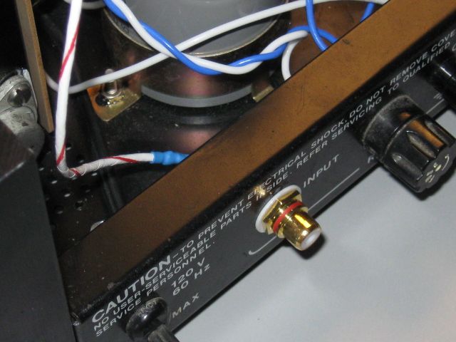
Once both channels were running happily with their new parts on the benchtop power supply I turned my limited attention to the chassis. The phenolic insulators sandwiching the RCA jacks in place were starting to crumble so, some shiny new jacks were fitted courtesy of ApexJr.com for 99 cents. The input wiring was done with 22AWG shielded wire.

Click the image to open in full size.

The pro Hafler models like the P125 and the P230 have a solid aluminum bracket for the ground connections between the main power supply caps. The DH200 and DH220 models only got some tinned wire which isn't very convenient or nice looking. I fashioned up a new bracket with some scrap...
Stormrider's Avatar
diyAudio Member
Posted in Uncategorized
Views 4436 Comments 2 Stormrider is offline
Old

Secure source for A123 Systems LiFePo4 cells

Posted 16th April 2013 at 04:53 PM by dvb projekt
Updated 30th November 2016 at 09:08 AM by dvb projekt (2nd source added)

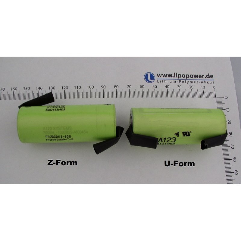
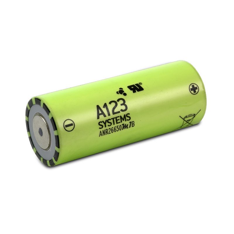
All members who want to use LiFePo4 cells from the leading company A123 Systems
and want a secure source to get no fakes,
could order them at Lipopower Ltd. in Germany.

The original cells are from the German A123 Systems distributors Reva or BMZ.

You could order them with or without solder taps.

Click the image to open in full size.Click the image to open in full size.


Also a Ri selection is possible.

International shipping and paypal payment is no problem!


P.S.: If you have any questions, send an e-mail to Mr. Karl-Heinz Hofmann with regards from me!

------------------------------------------------------------------------------------------------------


I´ve got an email from A123 Systems with a 2nd source

...
dvb projekt's Avatar
diyAudio Member
Views 2245 Comments 0 dvb projekt is offline
Old

Discrete transistor line amplifier stage

Posted 16th April 2013 at 01:18 AM by rjm (RJM Audio Blog)
Updated 16th April 2013 at 12:23 PM by rjm

Over the last couple of years most of my interest in audio has been with transistors. I've been slowly teaching myself to read and understand the circuits.

Circuits like this one for example. Not hard, but still a bit too complicated for me to understand without the helpful wikipedia markup attached.

Instead I've looked at primarily at the schematics I have for discrete audio preamplfiers, 1970's vintage typically. Based on what I've learnt so far, I've done up a "test mule" in LTSPICE, shown below.

It's not a circuit you should build. It's for pedagogical purposes, though it does actually work reasonably well - in simulation anyway. Its just a simple starting point to observe how the different parts interact under simulation.
Attached Thumbnails
Click image for larger version

Name:	RJM discrete.png
Views:	763
Size:	93.4 KB
ID:	959  
Attached Files
File Type: asc RJM discrete.asc (3.2 KB, 197 views)
rjm's Avatar
rjm
diyAudio Member
Posted in The Lab
Views 1146 Comments 0 rjm is offline

New To Site? Need Help?
Copyright ©1999-2017 diyAudio