
GM,
You are right, single driver but I believe that SpicyTL assume that a driver is always attached into the pipe's wall so I tried to 'hack' SpicyTL to simulate a speaker but in the 'middle' of the tube by attaching two speakers with opposing polarity... still playing with the 'hack'.
I have been using Hornresp to simulate TLs in the past but I've found this SpicyTL pretty convenient and able to simulate TLs with foam, wow!, Andrea did a fine job here!
Greets!
Understood, my main point is to not 'muddy the waters' with any B0$3 comparison/reference unless it directly applies.")
Speaking of which, are you aware of its 'half square wave antenna' variant that fills in its 3rd harmonic dip?
https://www.diyaudio.com/forums/subwoofers/9501-acoustic-wave-canon-6.html#post1175482 [sic]
Good to know, thanks!
Understood, my main point is to not 'muddy the waters' with any B0$3 comparison/reference unless it directly applies.
Speaking of which, are you aware of its 'half square wave antenna' variant that fills in its 3rd harmonic dip?
https://www.diyaudio.com/forums/subwoofers/9501-acoustic-wave-canon-6.html#post1175482 [sic]
Good to know, thanks!
Andrea,
I'm attempting to simulate the 'Wave Cannon' and I think that I found a way to do it not knowing if there is a better way since I'm not well versed on LTSpice.
I'm using the speakers back to back but with reverse polarity and this 'hack' is what I'm trying to offer to this thread. Not all the graphs run smoothly but enough to experiment and be ready to prototype
In my solution I had, also to calculate the 'port' diameter by hand as well as the volume (equal to the next section)
If SpicyTL supported directly to have pipes in front and back of the speaker maybe other interesting structures could be simulated like different bandpass subs, waveguides, etc.
Hi Drakonis,
you can't simulate the AWC by simply pairing two drivers with inverted polarity because that configuration assumes that one side of the diaphragm faces the outside of the TL anyway.
To front-load the driver you have to insert a segment of TL directly into the block (sub-circuit) of the driver. I have already experimented with this solution and it works very well, but (the reason is a bit complicated to explain) it cannot be done with the current version of SpicyTL. I've already made the changes that will allow to run this simulation and I'll make them available with the next release of SpicyTL.
Andrea,
Thanks for your attention to my post. I understand that my 'hack' is not a valid one. I'll wait for your next release then. Nonetheless I''ll continue playing and learning from your current deliverable, many thanks for sharing SpicyTL, I believe it is a very good tool and I'm grateful for it!
Thanks for your attention to my post. I understand that my 'hack' is not a valid one. I'll wait for your next release then. Nonetheless I''ll continue playing and learning from your current deliverable, many thanks for sharing SpicyTL, I believe it is a very good tool and I'm grateful for it!
Andrea,
Thanks for your attention to my post. I understand that my 'hack' is not a valid one. I'll wait for your next release then. Nonetheless I''ll continue playing and learning from your current deliverable, many thanks for sharing SpicyTL, I believe it is a very good tool and I'm grateful for it!
You had a good insight and I am pleased that you are working with SpicyTL.
Anyway, I'm working right now on a quick method to allow you to simulate a speaker mounted inside a waveguide.
AR
Andrea,
I have some questions regarding regarding how to interpret SpicyTL constructs:
I have some questions regarding regarding how to interpret SpicyTL constructs:
- Volume. If I set an [offset foam][volume][speaker][straight foam][bend.. also, all areas are 100cm2 (10x10cm) and the length before the 'bend' is 0.5m (5 liters), 'volume' is set to 5 Liters, then:
- Does it means that now I have a pipe of 10 Liters? up to the bend?,
- Only offset foam is affected?, Both offset foam and straight foam?
- If I want to simulate that such volume has foam, Should I specify a foam area bigger than than the one from the pipe?
- Bends. if I have [straight foam][180bend][straight foam], and all areas are 100cm2 (10x10cm). If I want to simulate a 0.5m straight pipes...
- Should I set each pipe to 0.5m?
- Should I set each pipe to 0.45m?
Andrea,
I have some questions regarding regarding how to interpret SpicyTL constructs:
- Volume. If I set an [offset foam][volume][speaker][straight foam][bend.. also, all areas are 100cm2 (10x10cm) and the length before the 'bend' is 0.5m (5 liters), 'volume' is set to 5 Liters, then:
- Does it means that now I have a pipe of 10 Liters? up to the bend?,
- Only offset foam is affected?, Both offset foam and straight foam?
- If I want to simulate that such volume has foam, Should I specify a foam area bigger than than the one from the pipe?
- Bends. if I have [straight foam][180bend][straight foam], and all areas are 100cm2 (10x10cm). If I want to simulate a 0.5m straight pipes...
- Should I set each pipe to 0.5m?
- Should I set each pipe to 0.45m?
No, it simply means that behind the speaker theres a 5 liters volume.
When designing a TL using correctly dimensioned segments, it is not recommended to use the volume block.
If you want to simulate a volume filled with foam simply use the straight foam block.
You have to enter the actual length of the straight segment, so 0.5 m
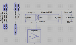
In SpicyTL 1.5 there is a sheet named SpicyWG. The integrated segment can simulate a speaker mounted in a waveguide. You can add blocks to the opening side to simulate more complex designs (tip: if you set offset equal to lenght, S_1 is the TL's area at the point where the loudspeaker is mounted). A new release will allow even more complex designs to be simulated.
AR
AR
Attachments
Andrea,
Thanks for sharing this new release!, I've started to play a little bit with it, specially with the SpicyWG model. I really continue learning a lot from your simulator and the importance of the damping inside of the different sections of a model.
I know that a real built baffle approximates its model as much as the model is accurate and the baffle construction follows it... but to err is human, so, let's say that your software has been teaching me how to tune a 'box' in a practical way with a RTA and a multimeter and for this invaluable experience I appreciate your efforts.
Thanks again Andrea!
(Not trying to be picky but trying to have your SpicyTL nice and shinning, maybe you would like to update the version at the 'Readme.txt')
Thanks for sharing this new release!, I've started to play a little bit with it, specially with the SpicyWG model. I really continue learning a lot from your simulator and the importance of the damping inside of the different sections of a model.
I know that a real built baffle approximates its model as much as the model is accurate and the baffle construction follows it... but to err is human, so, let's say that your software has been teaching me how to tune a 'box' in a practical way with a RTA and a multimeter and for this invaluable experience I appreciate your efforts.
- From my initial 'toying', Am I right to assume SpicyWG is modeled after a half wave resonator? (I ask because it seems to be sort of immune to line lengths but around half wave)
- Also I'm on the impression that at this moment, as it is, SpicyWG only responds to sections added after it but not to its beginning, Right?
- Also I tried having it with an offset about 0.01m,so, It should behave as a normal 1/4 resonator but I'm still digesting the results
- I Found this new 'air_load' module and It made me smile!. Can it be used, for instance, to model the effect of having a speaker close the the floor?, Ripole speaker proximity?...
Thanks again Andrea!
(Not trying to be picky but trying to have your SpicyTL nice and shinning, maybe you would like to update the version at the 'Readme.txt')
Ciao Drakonis,
at the moment no blocks can be added at the initial opening because the air load must be taken into account. In SpicyTL, where the air load is always proportional to Sd, the air load is modelled directly in the loudspeaker block. In SpicyWG the air load depends on the area of the opening, but to simulate more complex models dedicated blocks are needed: the air_load block and the front_loaded_speaker block, which I forgot in the download folder and which are not yet complete and working, are a first draft of it.
As you noticed, if you set the offset equal to zero you are designing a simple TL with the loudspeaker mounted at the beginnin of a tube.
Hi Andrea!
I started building my TL many years ago, mainly inspired by PMC speakers that use only foam as damping material. Unfortunately none of the TL simulation programs I knew and know could predict the performance of the foams in the TL. I'm glad you've made your program available to change that. Over the years I have built many prototypes, as well as copies of PMC speakers, on which I studied the effect of foams on the sound. I have also built simple models out of PVC pipes on which I tested the effect of the foams, which I think is quite different from wool or dacron.
If you feel like, take a look at a small part of my measurements and experiments with foams.
PCV pipe Transmission line | Flickr
Beyma ATL Transmission line | Flickr
ATL transmission line | Flickr
Thanks!
Dear Slocum
Thanks for the first TLS model that run on Apple computers! I had this idea of building a Atkins mini TLS (but not using KEF B110)
The original
Atkinson Mini TL HFN Nov78 | PDF | Resistor | Loudspeaker
Something new very close to the original TLS
IMF 100 “Complete@Home” LOUDSPEAKER SYSTEM
The parts 9 and 20 the two uppermost horizontal baffles of the pipe are visable in the pictures and have identical placement as the original.
My plan is to use 12 mm MDF and not bother with single and double layer 6mm plywood.
With your software I will have the oportunity to test different dampings and drivers even before buildning them, and things keep clean in silico,
Hi Andrea.
Thank you for your great work. That's exactly what I need for my new project. Especially now, when the prices for construction timber are extremely high and you have to think hard about experimental setups.
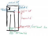
I'm struggling a bit with transferring the design data to the Spice model. I have attached a sketch. Have I interpreted it correctly? And how is the total length calculated. Is it enough to add all the "L" values?
The fiber blocks are not working and offset / bends are missing. I've tried to fix this by myself but this is too complex for me. Are you working on this?
Thank you
Andreas
Thank you for your great work. That's exactly what I need for my new project. Especially now, when the prices for construction timber are extremely high and you have to think hard about experimental setups.
I'm struggling a bit with transferring the design data to the Spice model. I have attached a sketch. Have I interpreted it correctly? And how is the total length calculated. Is it enough to add all the "L" values?
The fiber blocks are not working and offset / bends are missing. I've tried to fix this by myself but this is too complex for me. Are you working on this?
Thank you
Andreas
Attachments
Andrea,
Many thanks for sharing this, some years ago I built some Transmission Line Speakers, see the links below:
Jenzen-Illuminator
Jenzen-Illuminator_Steven
I was very impressed with their performance and I wanted to look into this, however, the tools available were limited until you set up this model. Having found your site I downloaded LTSpice and quickly built a model for all three drivers using your approach, the output aligned very well with the limited measurements I have. The next step I took was to add the crossover design into the model, very easy to do, with the results lining up very well with the information on Troels' website.
The next model I want to build is the integration of all three drive unit models, including cross overs, into one. The starting point would be to have three different speakers in the same model, do you have any hints or tips on how you think this can best be done?
Steve
Hi Andrea.
Thank you for your great work. That's exactly what I need for my new project. Especially now, when the prices for construction timber are extremely high and you have to think hard about experimental setups.
I'm struggling a bit with transferring the design data to the Spice model. I have attached a sketch. Have I interpreted it correctly? And how is the total length calculated. Is it enough to add all the "L" values?
The fiber blocks are not working and offset / bends are missing. I've tried to fix this by myself but this is too complex for me. Are you working on this?
Thank you
Andreas
Thank you very much Andreas,
I guess you had a problem with the "tapered_fiber" block: it's a block I'm working on and it's not actually in the folder. Again, I accidentally left the symbol in the download folder.
In the design you posted the speaker is mounted at the beginning of the line so there is no offset. The exact model starts with the driver and continues with a straight (or tapered) segment to the first 90 fold. The rest seems to be correct.
Andrea
Hi Andrea
Thank you for your fast response.
The length of the straight starts at the rear of the baffle, right?
A last question about the 90 degree bend. It has only one parameter for the area. In my case, the input are is much larger than the output area. Should I use the input or the output size?
Grazie sincero,
Andreas
Andrea,
Many thanks for sharing this, some years ago I built some Transmission Line Speakers, see the links below:
Jenzen-Illuminator
Jenzen-Illuminator_Steven
I was very impressed with their performance and I wanted to look into this, however, the tools available were limited until you set up this model. Having found your site I downloaded LTSpice and quickly built a model for all three drivers using your approach, the output aligned very well with the limited measurements I have. The next step I took was to add the crossover design into the model, very easy to do, with the results lining up very well with the information on Troels' website.
The next model I want to build is the integration of all three drive unit models, including cross overs, into one. The starting point would be to have three different speakers in the same model, do you have any hints or tips on how you think this can best be done?
Steve
Hi Steve,
if you have some practice with LTspice you can make the necessary changes to simulate two different speakers very quickly. First you need to create a new set of parameters for the second driver you want to use. The easiest way to do this is to copy the loudspeaker parameters to the main sheet and rename them, for example: RE_2, QMS_2, FS_2 etc.
Then you should modify the Speaker2 block diagram by replacing the parameters with the new ones (remember to also replace SD with SD_2 in the circuit that models the air load impedance).
Setting the third driver is a more complex job that requires an overhaul of the whole system: SpicyTL is set up to simulate up to 4 of the same speakers (or different, with the small modifications above), but for now only 2 are enabled.
Andrea
- Home
- Loudspeakers
- Subwoofers
- SpicyTL - Transmission Line Simulation Model