That's answered a lot of questions that I had. Thank you for taking the time to reply.It's a good approximation, but to get best accuracy you'll have to use this for determining corner bends.
Rather than dragging up another old thread could you explain some of the measurements Scott is referencing here (the ones in bold)?
~51Hz Fb compact MLTL. V. quick, lightly damped alignment. Internal dimensions:
L = 28.5in
W = 5in
D = 4.75in
St = 5.75in
Sv = 24.125in
Av = 3.14in^2
Lv = 4.5in
Vb (nominal) 11.1 litres [nearly].
Lag all internal walls 3/4in - 1in acoustic fiberglass, SAE-F10 felt, Ultratouch or similar & adjust to preference.
Last edited:
You're welcome!
driver centerline offset from top
vent centerline offset from top
vent area = sqrt(3.14*4/pi) = 2" dia.
vent length
driver centerline offset from top
vent centerline offset from top
vent area = sqrt(3.14*4/pi) = 2" dia.
vent length

Thanks again. I a bench joiner so confident with the build. The maths, not so much. 🤣You're welcome!
driver centerline offset from top
vent centerline offset from top
vent area = sqrt(3.14*4/pi) = 2" dia.
vent length
Yeah, I will when they're built.Cool, please post pics. 😉
Hi Andrea,
A question concerning the "Air parameters" of your SpicyTL 1.61.
What is the definition of Losses ? It should be equal to 50 ? What is the difference if it is set for example to 100 ?
Thanks
George
A question concerning the "Air parameters" of your SpicyTL 1.61.
What is the definition of Losses ? It should be equal to 50 ? What is the difference if it is set for example to 100 ?
Thanks
George
Thanks for creating spicyTL--looks fun and DIYers have good speaker design tools to play with to optimise designs now thank goodness. Not sure if already posted, but MJK's archive is at http://quarter-wave.com/. His FB user group that discusses diy TL projects etc is at https://www.facebook.com/groups/196578981099262/. I seem to recall MJK mentioning he is/was interested in doing some research on foam stuffing. I am having a play with spicyTL on my own enclosure I made a couple of years ago originally modelled in @schmeet's TL program (https://www.diyaudio.com/community/threads/transmission-line-modelling-software.220421/ ), then, after making, Hornresp. Still figuring out how to apply the foam/fibre filling of the line but will persevere 🙂
Last edited:
Ciao Andrea,Hi Steve,
if you have some practice with LTspice you can make the necessary changes to simulate two different speakers very quickly. First you need to create a new set of parameters for the second driver you want to use. The easiest way to do this is to copy the loudspeaker parameters to the main sheet and rename them, for example: RE_2, QMS_2, FS_2 etc.
Then you should modify the Speaker2 block diagram by replacing the parameters with the new ones (remember to also replace SD with SD_2 in the circuit that models the air load impedance).
Setting the third driver is a more complex job that requires an overhaul of the whole system: SpicyTL is set up to simulate up to 4 of the same speakers (or different, with the small modifications above), but for now only 2 are enabled.
Andrea
is now possible to simulate 3 identical drivers in the same multichamber box, just twice copy and paste the same model?
All three are facing outside, two wired in series sharing the same chamber and the third wired in parallel to them with few crossover components but sited in a second different chamber. I'm trying without getting error, so just to be sure.
(If you can I wiil post what I'm trying to simulate...just starting to play...).
Thanks
Just following on from that, can you advise what is the range of numerical adjustment for fibre "filling rate". Is it a percentage? If I wanted to use 17 g/l would I use 100% for fibre filling rate-or with 8g/l ~50%.Thanks for creating spicyTL--looks fun and DIYers have good speaker design tools to play with to optimise designs now thank goodness. Not sure if already posted, but MJK's archive is at http://quarter-wave.com/. His FB user group that discusses diy TL projects etc is at https://www.facebook.com/groups/196578981099262/. I seem to recall MJK mentioning he is/was interested in doing some research on foam stuffing. I am having a play with spicyTL on my own enclosure I made a couple of years ago originally modelled in @schmeet's TL program (https://www.diyaudio.com/community/threads/transmission-line-modelling-software.220421/ ), then, after making, Hornresp. Still figuring out how to apply the foam/fibre filling of the line but will persevere 🙂
Looks like there is no offset block, 80 and 90 deg bends with fibre, only foam if not mistaken. Are the only options to leave empty or use foam?
Just a minor edit you may or may not want to consider is the spelling of "length" at some point.
Last edited:
To my understanding is not a percentage but the area of the section filled. If the area is 120cm2 and you want to fill 50% put in it 60; if you fill 100% put in it 120. Then the density is set in a different place. But let us Andrea confirm...Just following on from that, can you advise what is the range of numerical adjustment for fibre "filling rate". Is it a percentage? If I wanted to use 17 g/l would I use 100% for fibre filling rate-or with 8g/l ~50%.
Looks like there is no offset block, 80 and 90 deg bends with fibre, only foam if not mistaken. Are the only options to leave empty or use foam?
Just a minor edit you may or may not want to consider is the spelling of "length" at some point.
Cool, sounds plausible. Thanks. The resulting spl response didn’t look quite right.To my understanding is not a percentage but the area of the section filled. If the area is 120cm2 and you want to fill 50% put in it 60; if you fill 100% put in it 120. Then the density is set in a different place. But let us Andrea confirm...
In the most recent paper page 15 Martin refers to 0.5lb/ft^3 see http://www.quarter-wave.com/TLs/TL_Alignments.pdf for 3/4 of the line length. But the term— stuff to taste has also been mentioned elsewhere. I used roughly that amount to start with when the driver was new but reduced that after some time.16 kg/m3 = 0.998847 its/in2
A higher density than in any of the lines i have drawn IIRC.
One has to ask the question why the foam effectively eats line volume, and why is the speed of sound changed. That has been a red herring in the past.
dave
excerpt:
“The tapered and expanding transmission line results shown in Figures 10 and 11 respectively include 0.5 lb/ft^3 of stuffing in the first 3/4 of the line’s length. Changing the amount and location of fiber stuffing in a transmission line is a tweak often used to fine tune a transmission line’s SPL results. In Figures 10 and 11 the sharp peaks and nulls in the SPL results (top plot) of Figures 7 and 8 have been reduced to a ripple which looks reasonable for the tapered transmission line but is still significant for the expanding transmission line.”
BASS REFLEX MODEL, is this correct?
I know that there is now the Port model, but I'm asking if the following model would be OK for a bass reflex of 42L (with a reflex tube of 7cm diameter long 14 cm), with 3 drivers (two in series and one in parallel to the ampli).
I know that there is now the Port model, but I'm asking if the following model would be OK for a bass reflex of 42L (with a reflex tube of 7cm diameter long 14 cm), with 3 drivers (two in series and one in parallel to the ampli).
Attachments
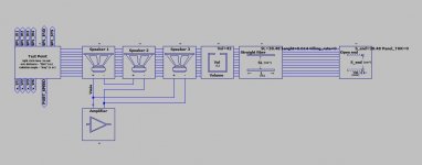
It seems Andrea is not around to answer to all our questions and unfortunately the model is too way complex to be used without training...
In any case I have another question: is there a minimum lenght for the "straight fiber" block to work? So if I put a panel between two chambers with a Variovent (or Flow resistor) can I model it as a "stright fiber" block with a lenght equal to the panel thickness fully filled sited between two "Volume" blocks?
In any case I have another question: is there a minimum lenght for the "straight fiber" block to work? So if I put a panel between two chambers with a Variovent (or Flow resistor) can I model it as a "stright fiber" block with a lenght equal to the panel thickness fully filled sited between two "Volume" blocks?
I hope the development and improvement of spicyTL will continue somewhere if not diyaudio. I think it’s application as a spice file is interesting.
I think it could work. Have you tried comparing that model with the port block?BASS REFLEX MODEL, is this correct?
I know that there is now the Port model, but I'm asking if the following model would be OK for a bass reflex of 42L (with a reflex tube of 7cm diameter long 14 cm), with 3 drivers (two in series and one in parallel to the ampli).
The volume block is a lumped parameter model and contains no information on the surface area exposed to the damping panel. I would rather try with two empty TL sections.It seems Andrea is not around to answer to all our questions and unfortunately the model is too way complex to be used without training...
In any case I have another question: is there a minimum lenght for the "straight fiber" block to work? So if I put a panel between two chambers with a Variovent (or Flow resistor) can I model it as a "stright fiber" block with a lenght equal to the panel thickness fully filled sited between two "Volume" blocks?
SpicyTL 1.7 is available for download.
The 'end' block has been simplified and the model of the air load at the opening has been improved.
I have added a tool within the amplifier block that simplifies the simulation of the loudspeaker impedance curve.
At the following address the download and updated instructions:
https://transmissionlinespeakers.com/en/spicytl-english/
- Home
- Loudspeakers
- Subwoofers
- SpicyTL - Transmission Line Simulation Model