Just playing with aperiodic reflex.
This was modeled with the "Volume" block and the modified "Port" block.
The driver is a ScanSpeak 18W8531 in a 100L box. The port parameters are:
D_port=10 L_port=20 Vbox=100 Qbox=5
The quantity of damping material varies from 0 to 60 g with step of 10 g
The density inside the port is automatically calculated from the parameters above.
The graph shows the responce (driver, port and system) and the impedance curve.
It would be interesting to have some measures available to fine tune the model.
Attachments
Hi Andrea, where You place a .step command in SpicyTl if that's possible? The figures to fill the "foam" field, it is 20 40 60 and so on, what magnitude they stand for? Thanks again. Besides I modelled in Spicy a box that was costructed purely under asumptions, and the program show exactly the shortcomings revealed by the measurement. Thanks for this fine piece of software.
Hi Mosquito,Hi Andrea, where You place a .step command in SpicyTl if that's possible? The figures to fill the "foam" field, it is 20 40 60 and so on, what magnitude they stand for? Thanks again. Besides I modelled in Spicy a box that was costructed purely under asumptions, and the program show exactly the shortcomings revealed by the measurement. Thanks for this fine piece of software.
you must place the .step parameter in the main sheet even if the parameter is defined in the subcircuit. If the parameter is defined in the block editor you have to cancel it otherwise the .step parameter will be ignored (the deletion will not be saved anyway and at the next opening the parameter will be present again in the editor). It would have been more convenient to use the .step command directly in the subcircuit but this can't be handled for a hierarchy issue.
Many thanks for your feedback!
Andrea
The figures to fill the "foam" field, it is 20 40 60 and so on, what magnitude they stand for?
Are you referring to the DENS parameter in the main sheet? It's the material density in kg/m³

S_foam is the cross sectional area of the TL occupied by the foam in cm2No, in the individual blocks, "foam= X"
Yes. I have seen dual drivers in commercial TLs from a while ago. I wanted to play with the location and see if there was some advantage to be had. I have not seen much on this except for a few patents by Bose that came up in the referenced thread.
I wasn't interested in modeling an ideal speaker. I was interested in how adjusting placement could possibly improve things using two drivers. I thought the best way to do this was to just give it a try with the simplest system possible to minimize variables.
BTW, the speaker placement at 1/3 and 1/5 was also discussed on Martin's FB page and he was not sure what effect the different placing would have. So I think that certainty on the "correct" way to place two drivers in a TL might lead one down the wrong path.
this is good thinking and while i dont have an answer for you, i do have an alternative to the idea youre presenting that you might relate to as i have. If we study a thermo acoustic motor it quickly becomes obvious if a TL speaker person,,that theres a distinct similarity in the pressure phase of our TLs, thats used as the mechaism to drive a self propelled system. The hot and cold regions separated by steel wool , are a flame and a wet towel on a closed pipe which will generate a backwave off the closed end where a cycke of pressure will
Begin of hot/cold resulting in a steady state oscillation. The ‘fulcrum’ is where we put the driver in a TL as the pressure node of the odd harmoinc. That seems to 0.349. But also is seen at 0.217, 0.424 066,0.714 and 0.848. The 0.349 position in the thermo acoustic motir is the affextive middle of the pump system action and that same affect is used in the emergency cooling systems pumpless ducting in a nuclear reactor on US NAVY Submarines and it yet another version of this..
If you draw the fullwave from zero of the qw we commonly use to tune a pipe in, those all become approximately the anode and nodes crossing pressure/velocity for 3/4,5/4 forms of the qw.
But what if we want to use that mechanism further? Put a pipe on the opposite output of the driver. in order to do so you must use that same chunk of 1/3. Except in order to maintainphase the driver in the other has to go back to the closed end. If you want to do anything from that point. You look at phase and keep chopping at intervals of or adding them in x2, or 1/2s, inckuding folding at thise. A second driver at the other side is as far away as the offset produceds from the ed of the system(Z to ambient?
In horn response this can all be simmed and phase is observed in that window where it stays at 0/90/180/270/360....720 at the odd harmonics. Etc. But that becomes the tapped horn sim with a rear chamber(same lengths used).
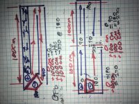
The pic is a generic size for the initial TL optomised as a pipe in horn response. A very good ‘start’ if playing pump or cannon in a pipe. especialky one that later is a steepped expansion from this with that extra drive (polar opposite in this case as you'll see in phase plot).
Hope that helps or leads you to find something like multiple enyree math
Attachments
Heres the plain jane example . But if you observe this it might help decide on a drver location. Because you can move that driver by 100 cm in either pipe. And ive looked at the bose stuff too. i understand what you might refer to in that i think.
The short polar opposite (rear pipe) either fully in or out is ideal for the phase cycle of pressure. but that adds as the driver location in the long front pipe(offset driver TL) is double down on the 3rd harmonic and will spike that location it was smoothing over. it just gets complicated further.... but by then its obvious theres a gain and results fir a robust driver in the right sized pipe. The furthering of this idea can ve seen in a not so obvious version of roar or keystone pipe shapes but the folding/ layout looses some small positions in turns if not for a smaller vas so its all narrow and tifht.
The short polar opposite (rear pipe) either fully in or out is ideal for the phase cycle of pressure. but that adds as the driver location in the long front pipe(offset driver TL) is double down on the 3rd harmonic and will spike that location it was smoothing over. it just gets complicated further.... but by then its obvious theres a gain and results fir a robust driver in the right sized pipe. The furthering of this idea can ve seen in a not so obvious version of roar or keystone pipe shapes but the folding/ layout looses some small positions in turns if not for a smaller vas so its all narrow and tifht.
Attachments
Last edited:
Just downloaded it today 11/3/21 ver 1.4
The spice program installs and runs without error.
however the spicy 1.4 will not run even the included example
too many errors to list.
also seems to be missing files in the package.
Any comment.?
The spice program installs and runs without error.
however the spicy 1.4 will not run even the included example
too many errors to list.
also seems to be missing files in the package.
Any comment.?
Just downloaded it today 11/3/21 ver 1.4
The spice program installs and runs without error.
however the spicy 1.4 will not run even the included example
too many errors to list.
also seems to be missing files in the package.
Any comment.?
The only thing that comes to my mind is that you have run the program from the preview folder of winzip without having first unzipped the folder.
Can you post a screenshot?
Hello Andrea,
Thank you for sharing and developping SpicyTL. I just dowloaded and installed the 1.4 version and it looks promising!
I am trying to simulate a TL and have a couple of questions. I have already made some simulations using Hornresp and am now trying to move to SpicyTL in order to have more flexibility simulating the damping material inside the enclosure. However, I can't find some parameters such as the acoustic path length between the output of the loudspeaker and the output of the line in SpicyTL.
- How is the "acoustic path" length taken into account in SpicyTL? Is it assumed that both outputs are coincident or is there a way to set this length?
- About the damping material modelling, how did you measure the parameters Losses (K_air in former versions), K_1 and K_2 ?
Is the user supposed to tweak those parameters ?
- I am also wondering the same question for c_1 (c_foam) and c_2 (c_fiber).
Thanks,
Slk
Hello Andrea,
Thank you for sharing and developping SpicyTL. I just dowloaded and installed the 1.4 version and it looks promising!
I am trying to simulate a TL and have a couple of questions. I have already made some simulations using Hornresp and am now trying to move to SpicyTL in order to have more flexibility simulating the damping material inside the enclosure. However, I can't find some parameters such as the acoustic path length between the output of the loudspeaker and the output of the line in SpicyTL.
- How is the "acoustic path" length taken into account in SpicyTL? Is it assumed that both outputs are coincident or is there a way to set this length?
- About the damping material modelling, how did you measure the parameters Losses (K_air in former versions), K_1 and K_2 ?
Is the user supposed to tweak those parameters ?
- I am also wondering the same question for c_1 (c_foam) and c_2 (c_fiber).
Thanks,
Slk
Hi Slk,
in SpicyTL the outputs are coincident.
The parameters were derived from measurements on a TEST TL.
Especially for the foam, no change in parameters is required by the user. For fibre, the parameters refer to uncompressed Dacron. When using other fibrous materials an adjustment may be necessary, but a TEST TL is needed for comparison.
Andrea
Andrea/Guys,
Do you know if SpicyTL-1.4.zip is still available?, whenever I try to download it I get an error (DNS lookup failed for the requested URL: "andrear59.sg-host.com").
I would appreciate your help on this or your pointers to this excellent work (Kudos Andrea!!)
-Miguel-
Do you know if SpicyTL-1.4.zip is still available?, whenever I try to download it I get an error (DNS lookup failed for the requested URL: "andrear59.sg-host.com").
I would appreciate your help on this or your pointers to this excellent work (Kudos Andrea!!)
-Miguel-
Andrea/Guys,
Do you know if SpicyTL-1.4.zip is still available?, whenever I try to download it I get an error (DNS lookup failed for the requested URL: "andrear59.sg-host.com").
I would appreciate your help on this or your pointers to this excellent work (Kudos Andrea!!)
-Miguel-
Hi Miguel,
I had to move the site to another server and had missed this problem.
Everything should be fine now. Many thanks for the report and the kudos 🙂
Andrea
Andrea,
I really appreciate your attention to my request!!!, it is working now 🙂, I wish you a very good day. (Now I'm like a child with a new toy)
I really appreciate your attention to my request!!!, it is working now 🙂, I wish you a very good day. (Now I'm like a child with a new toy)

Hi Andrea,
I hope this won't be too disturbing for you or the respectfully nice members of this forum. Usually I tend to be on the lurking side, therefore I'm not posting too much, nonetheless I've learned a lot! during these 20 years.
Lately I've been 'playing' with OB constructions that have been quite satisfactory but with non-sanctioned speakers so I have not published them. They work fairly smooth from 30hz up to 18Khz (Car sub-woofers, High Q, heavy cones, Eminence mediums and bullet tweeters very 'tamed' -I won't use them anymore!- in 'L', 'H' and finishing a baffle-less OB)
So, now I'm about to explore three new candidate projects:
- First, small TL bookshelf, Dayton based, speakers (1 Tweeter, Two 4" woofers -easier to
cancel deeps-) per side most likely active for my son (from Mexico it is cheaper Digital
amps than copper when coils start to be around a 1mH)
- Second, I have several years thinking on a small two way Synergy, Paraline? system
using the horn for 'high' and 'mid's down to 150hz and -Anathema- maybe a sort
Bose's wave cannon for lows (dual TL around a Single/isobaric speaker). The reasons
are that on the pass band you suppose to reach, not really low extension, but high
gain to match the horn with simple speakers. Also, a folded TLine is shorter than a TH
horn and less complex BUT, here is the twist, with tapered pipes, -Smaller!-, and
only the short section with some foam to tame the line, I know, patent is about no
filling in order to maximize output (On your SpicyTl that seems to simulate promising
*More on this matter later*). These for my Dad, small horn sitting on a small footprint
'cannon'?, so they would be a sort of short stand columns... Why Synergy?, because
I was intrigued since the Bass forum, and, Dad doesn't hear too well now so I guess
the promised coherence would help...
- A 'stereo' speaker but active with reflectors a la Jordan's Aurora
(http://elias.altervista.org/html/SingleSpeakerStereo.html) or like Jordan's old
papers (now not available) for my Girl. Most likely the 'lows' section would be
a TLine alike the first project.
-Miguel-
Andrea,
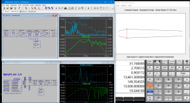
I'm attempting to simulate the 'Wave Cannon' and I think that I found a way to do it not knowing if there is a better way since I'm not well versed on LTSpice.
I'm using the speakers back to back but with reverse polarity and this 'hack' is what I'm trying to offer to this thread. Not all the graphs run smoothly but enough to experiment and be ready to prototype
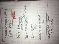
In my solution I had, also to calculate the 'port' diameter by hand as well as the volume (equal to the next section)
If SpicyTL supported directly to have pipes in front and back of the speaker maybe other interesting structures could be simulated like different bandpass subs, waveguides, etc.
I'm attempting to simulate the 'Wave Cannon' and I think that I found a way to do it not knowing if there is a better way since I'm not well versed on LTSpice.
I'm using the speakers back to back but with reverse polarity and this 'hack' is what I'm trying to offer to this thread. Not all the graphs run smoothly but enough to experiment and be ready to prototype
In my solution I had, also to calculate the 'port' diameter by hand as well as the volume (equal to the next section)
If SpicyTL supported directly to have pipes in front and back of the speaker maybe other interesting structures could be simulated like different bandpass subs, waveguides, etc.
Attachments
- Home
- Loudspeakers
- Subwoofers
- SpicyTL - Transmission Line Simulation Model