Here you go:
View attachment 924993
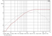
Response shape and level now drastically different to the MJK model, but steep roll-off largely still there. I had to increase K_fiber to 500 to get the response of my original TL design close to the MJK prediction too. It suggests your fibre model isn't correct.
Thanks cs,
the difference could also be due to the material used to develop the model because I found a very good correspondence between the measurement on my test line and its simulation.
SpicyTL is mainly dedicated to foam, which has a much more homogeneous behavior: I used material from many manufacturers, but the density characteristics were always almost identical to each other while I tried only two types of Dacron that turned out to be very different.
Anyway let me do some test. The model is designed to use two parameters (in addition to the speed of sound, which for the fiber has no significant impact) to define amplitude and decay of the response and currently are concentrated in a single parameter for simplicity. Separating them could make the modeling of the response of various materials more flexible.
Foam is able to significantly slow down the wave velocity
in the tunnel, so it is possible to virtually lengthen the
tunnel. This may be utilized to physically reduce the size of
the enclosures.
Many thanks dkjosness, I did not know this publication. That's exactly what I've observed as well.
I have read other papers dedicated to poroelastic materials that talk about slowing down in the speed of sound perfectly in line with what I have experienced.
Slow it down, Or just create a much greater affective distance to weave in and out of the fibers or pourous materials? Its no longer a beeline from A—B, its much longer as switchbacks and zigzags? Some heat, some mass loading, some high frequencies lost in the confusion and chaos while the lower ones just carry on to exit. Might be the coolest part about TL, the art of stuffing and strategies.
Any luck with the foam taming excursion in excess, or between velocity changes in the high Q drivers?
http://www.bobgolds.com/AbsorptionC...VJMs4W-uqekYZKsN_H5uKGgKdUNc7FRjmrf9w9OEf6QLc
.
Thanks cs,
the difference could also be due to the material used to develop the model because I found a very good correspondence between the measurement on my test line and its simulation.
It's possible, although that doesn't fit well with the fact that hundreds of designers have used the MJK models over the past 20 years, and always achieved excellent agreement with the simulation, despite using stuffing from a variety of sources.
There have also been many measurements made on different fibre materials in the past (eg. long fibre wool, acoustastuff, etc) and they don't differ much.
Some years ago, I asked Martin if he had done any measurements on foam. He said he hadn't, but he had seen an impedance plot of a TL speaker which used foam lining. He said the plot exhibited the classic 'double-hump' characteristic of a reflex box, indicating that the foam wasn't actually providing much damping. He postulated that the line was just acting as a very long reflex port, where the main function of the foam was to constrict its cross-sectional area.
Here is a link to a paper titled "Analysis of Damping Materials in a Transmission Line Loudspeaker System." It was presented at the New Trends in Audio and Video conference held in Poland in 2012.
http://www.eletel.p.lodz.pl/docs/aktualnosci/Lusztak_Krzysztof.pdf
Interesting paper.
It's just a pity he didn't include the type of damping arrangement most people use, which is to fill the line cross-section, but vary the density. Just sticking a 3cm layer of wool on the walls isn't going to do much.
It's also somewhat misleading because he has conflated the effect of the stuffing with the line taper, both of which increase the effective acoustic length for a given physical length. Both reduce high frequency ripple too.
It's possible, although that doesn't fit well with the fact that hundreds of designers have used the MJK models over the past 20 years, and always achieved excellent agreement with the simulation, despite using stuffing from a variety of sources.
There have also been many measurements made on different fibre materials in the past (eg. long fibre wool, acoustastuff, etc) and they don't differ much.
Some years ago, I asked Martin if he had done any measurements on foam. He said he hadn't, but he had seen an impedance plot of a TL speaker which used foam lining. He said the plot exhibited the classic 'double-hump' characteristic of a reflex box, indicating that the foam wasn't actually providing much damping. He postulated that the line was just acting as a very long reflex port, where the main function of the foam was to constrict its cross-sectional area.
I too had an excellent match with the simulation. You must not forget that we are talking about simulation models that do not take into account the real response of the speaker, and that (whichever model you use) the result of the simulation will never be perfect, unless you are using an ideal speaker, which unfortunately does not exist.
I will make the necessary changes to the model so that it can be more adaptable to various materials, but already now I do not think that the difference in the system response (for now you are very focused on the opening) between the two simulations goes beyond the difference between the ideal speaker and the real one.
It is difficult to comment on the second part being a reported testimony and in the absence of who would have made those observations.
but already now I do not think that the difference in the system response (for now you are very focused on the opening) between the two simulations goes beyond the difference between the ideal speaker and the real one.
That in effect, is saying that the MJK software in inaccurate, and your software is correct. I think most people here will draw their own conclusions about that.
Your prediction of the port output (both foam and fibre look very similar) is wildly different to the MJK model. The level, response shape, and roll-off are all dramatically different. That has nothing to do with the speaker or any non-ideal behaviour. MJK's models have been verified repeatedly over a 20 year period, and they are not wrong!
It is difficult to comment on the second part being a reported testimony and in the absence of who would have made those observations.
Translated: You are accusing me of lying!
That in effect, is saying that the MJK software in inaccurate, and your software is correct.
This is your conclusion and it is quite fanciful
Translated: You are accusing me of lying!
I just said that I can't comment on sentences reported by others!
Interesting paper.
It's just a pity he didn't include the type of damping arrangement most people use, which is to fill the line cross-section, but vary the density. Just sticking a 3cm layer of wool on the walls isn't going to do much.
It's also somewhat misleading because he has conflated the effect of the stuffing with the line taper, both of which increase the effective acoustic length for a given physical length. Both reduce high frequency ripple too.
Why dont you ask Martin (today) what he thinks... but dont ask him in a way gives him the impression youre questioning his papers, etc. you have to avoid that human characteristic if defense. With any success or confidence in your motoves, you might find Martin has (and continues) to loosen up the reins on some of his rigid topics of 13-20 years ago.
Not putting words in the mans mouth, but he had renigged a lot of ‘exact’ expresions of many things now that he is recognized as authority on the subject(s) instead of having to disprove others and fight uphill with only a limited choice of approaches to do so and be affective.
That means ‘diversity, ‘alternate approaches’ and more ideas are becoming relevant and even experimented by him as he approaches retired. His most recent work on ducts, stubs and damping them in vsrois amounts and locations in a TL. Even as a compound version. With a bass reflex opposing a qW pipe, with similar size and tuning. To which we shared a few messages and ideas which, ended up with us both buying the sane book on the subject. (And a funny coincidence as we were both working on the same type of thing at the time, as personal projects. of course, he had the missing piece i needed to make mine function best... the old mans still got it! I predict a return to the TL and version 2.0 is a MLTL morph with a similar compounded pipe or bass reflex using the opposite side of the cone. Or scattered stubs at harmonics intervals(folding).
Attachments

It's also somewhat misleading because he has conflated the effect of the stuffing with the line taper, both of which increase the effective acoustic length for a given physical length. Both reduce high frequency ripple too.
Not the first time that has happened. The paper has many shortcomings.
Conclusions are questionable.
dave
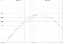
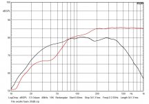
Today I did some testing on the _fiber model focusing particularly on the port output level.
I used my smallest test line: 1m length, SL=SD (35 cm2), RS100-4 driver, 100% filling with 60g of uncompressed Dacron (17kg/m3).
As I expected, the correspondence between measurement and simulation is almost perfect. The parameters used are those currently entered in SpicyTL as default values. I left the full graph, but given the size of the driver, anything below 50 Hz is not significant.
Thanks to the report of cs I also added a second parameter to the model which helps to better define the high frequency roll-off. This may come in handy when modeling the response with different damping materials. It was useful to further improve the response of the _foam models that were showing a slightly steeper roll-off than measurement.
Attachments

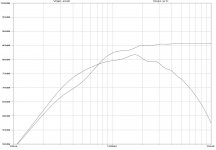
This is the simulation with 50 g of foam. The average sheet height is 2.5 cm which results in about 70% fill. Using the straight_foam block I simply set S_foam to 25 cm2 (the TL is 10 cm wide).
Attachments
Good to see some calibration of some polystuff. There is a need for knowing what high densities are so that TL models become more useful for simulating aperiodic boxes.
100% filling with 60g of uncompressed Dacron (17kg/m3).
about 1 lb/ft3. Some 2x or more dense than i ususally see specified so if non-linear perhaps a data point outside of our interest. But not enuff density to take us to aperiodic.
Line cross-section seems small for the driver you are using so the effect of the (suspected) too small line could be choking/affecting response.
Also, i expect that “Dacron” covers a wide range of different materials. Perhaps test something known, like acoustastuff, i’d be happy to mail you some of you do not have easy access.
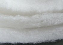
How fluffy is the dacron out of the line?
Thanx for doing this, but i suspect many variables not accounted for and the resulting data needs to be confirmed and fleshed out.
dave
Good to see some calibration of some polystuff. There is a need for knowing what high densities are so that TL models become more useful for simulating aperiodic boxes.
100% filling with 60g of uncompressed Dacron (17kg/m3).
about 1 lb/ft3. Some 2x or more dense than i ususally see specified so if non-linear perhaps a data point outside of our interest. But not enuff density to take us to aperiodic.
Line cross-section seems small for the driver you are using so the effect of the (suspected) too small line could be choking/affecting response.
Also, i expect that “Dacron” covers a wide range of different materials. Perhaps test something known, like acoustastuff, i’d be happy to mail you some of you do not have easy access.
How fluffy is the dacron out of the line?
Thanx for doing this, but i suspect many variables not accounted for and the resulting data needs to be confirmed and fleshed out.
dave
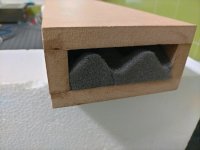
The line c/s equals Sd and the line volume is 3 times Vas. I think this is quite typical for a test line.
It would be very interesting to receive the material, but I'm not just around the corner.
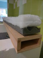
The Dacron I used is very fluffy. Take a look at the picture of the material outside the TL.
If you can provide me with a design and some measurements I don't think it should be too difficult to set up a model to simulate aperiodic boxes.
Attachments

The line c/s equals Sd
That is rarely enuff… and Sd is mostly irrelevant.
That looks far from teased sufficiently.
Small Packet post is cheap. And i have lots of acoutastuff. How many grams do you think would be adequate?
dave
I built several different TLs with polyester fibre damping, using Augspurger TL software. Measurements were exact replica of the simulation.The line c/s equals Sd and the line volume is 3 times Vas. I think this is quite typical for a test line.
From the experience: SrossSect.=Sd and Vb=3Vas are not universal rules of thumb! Good TL depends heavily on TS parameters Qts, Fs and Vas together, besides TL length, tapering, stuffing and driver offset.
The quickest comparison between foam and fibre stuffing would be simulation and measurements of straight "tube" optimised for the driver used, with optimum amount of fibre and foam stuffing, obtaining the same -3dB cut-off frequency and the same ripple. Only than we can compare the quality of the simulation and declare the winner of the foam/fibre duel.
Anyway, I am very interested in your software and I would like to express gratitude for your effort to support DIY community. Please continue improving SpicyTL!
Last edited:
I built several different TLs with polyester fibre damping, using Augspurger TL software. Measurements were exact replica of the simulation.
From the experience: SrossSect.=Sd and Vb=3Vas are not universal rules of thumb! Good TL depends heavily on TS parameters Qts, Fs and Vas together, besides TL length, tapering, stuffing and driver offset.
The quickest comparison between foam and fibre stuffing would be simulation and measurements of straight "tube" optimised for the driver used, with optimum amount of fibre and foam stuffing, obtaining the same -3dB cut-off frequency and the same ripple. Only than we can compare the quality of the simulation and declare the winner of the foam/fibre duel.
Anyway, I am very interested in your software and I would like to express gratitude for your effort to support DIY community. Please continue improving SpicyTL!
I'll try to explain myself better: c/s = Sd is not a rule thumb for designing a good TL, and I've never said this, but is a PERFECT rule of thumb for designing a good TEST TL. More, having c/s = Sd avoids the step of normalizing the opening response to have a correct representation of the system response. I also listed the Vol/Vas ratio only to point out that this is not an undersized TL.
I also experimented with a TL of circular shape and c/s much larger than Sd, just to verify that both gave reliable results and that the rectangular shape did not create alterations in the response. Once I verified this, I returned to the rectangular shape, which is much more practical for foam simulations. The rectangular shape was also essential for me to model the effect of the offset on the response.
Regarding the foam vs. fiber comparison, I personally am not looking for a winner. Both materials have reason to exist and maybe even coexist within the same project. Obviously, experimenting with foam for a long time, I got an idea on the subject, but from now on I will be very cautious about expressing personal opinions on this. I didn't realize I was dealing with something like a religion 🙂
Thank you very much for the gratitude shown, I really appreciate it 🙂
Attachments
That is rarely enuff… and Sd is mostly irrelevant.
That looks far from teased sufficiently.
Small Packet post is cheap. And i have lots of acoutastuff. How many grams do you think would be adequate?
dave
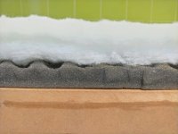
60 g of dacron and 50 g of foam. I confirm that Dacron can be pressed at will.
I'll send you my address via pm. To fill the entire TL would need 3.5 L of material.
Attachments
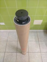
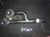
How big(area in crossection) is your line? I run rs100-8 in offset 42/80cm entries to 3” sched 40 pipes(45.6cm2) at 122cm total. I give up few cm on the end offsetting the exit a bit upstream.. These are fully stuffed, however that is very very open and teased. Another version (pic) i played around with for fun was an Mtm is two seperate 3” pipes that converge as a single and exit with the short stub at the end. Same length essentially but with some bends and bringing the exit closer to the drivers.
Just wondering if you prefer a size?
Just wondering if you prefer a size?
Attachments
- Home
- Loudspeakers
- Subwoofers
- SpicyTL - Transmission Line Simulation Model