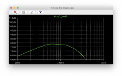
It will be interesting to see the two simulations with fibre compared.
What should I enter for the 'Filling rate' parameter?
I set the tapered line lengths such that they already included the bends, assuming the centre line of each segment defines its length.
Just tried reducing the length of each line segment (from 0.44 to 0.35m) but the only effect was to shift the whole plot to the right. That is, it tuned higher in freq. The general shape of the response was the same, including the large first dip.
Adding foam to the final line segment reduced the ripple slightly, but the rest of the plot was largely unchanged.
The port output plot looks very odd, peaking around 90Hz.
The MJK software plot is exactly the same as the SpicyTL plot, namely 10 to 1000Hz (log) and 60 to 110dB. The stuffing density was set to 1lb/cu.ft in the chamber and first line segment and to 0.5lb/cu.ft in the 2nd segment. 3rd segment has no stuffing. From experience I know that making the stuffing density reduce roughly in proportion to the line taper gives best results.
SpicyTL also takes into account the cross-sectional variation due to a bend.
There is no doubt that the TL is not perfectly optimised. In particular, you immediately notice a coupling chamber that is disproportionate to the total volume and an offset that is too small compared to the total length. With all that volume at your disposal you could do a lot more, but it's still a great design for experimenting with SpicyTL and I think that's what you were going for. Despite everything, the midrange ripple isn't as pronounced as you'd expect for a less than optimised TL. That large dip is due to the peak in the opening response and should definitely be controlled. Keep in mind that SpicyTL's prediction is very accurate and you will find that peak in your final design as well.
If I have interpreted your data correctly, the comparison is between a TL where the coupling chamber and the first segment are completely filled with fibre (plus the third with a 50% filling) and a TL where only a 1.5 cm thick sheet is applied in the chamber and the first two segments. 1.5 cm thickness is far too little: consider that the typical thickness of a sheet is 2.5 cm and that you should fill at least 50% of the total volume.
Regarding the MathCad graph I was referring to the shape (not the scale).
Andrea
What should I enter for the 'Filling rate' parameter?
Is the percentage of the total c-s area filled with damping material.
For the foam I would start with 50% and eventually go to increase.
For the fiber evaluate according to your experience: the density is referred to that of the fiber not compacted, but increasing the parameter k_fiber you can evaluate higher densities.
But what is the density assumed?
The MJK worksheets assume a maximum density of 1lb/cu.ft.
There is no doubt that the TL is not perfectly optimised. In particular, you immediately notice a coupling chamber that is disproportionate to the total volume and an offset that is too small compared to the total length. With all that volume at your disposal you could do a lot more, but it's still a great design for experimenting with SpicyTL and I think that's what you were going for. Despite everything, the midrange ripple isn't as pronounced as you'd expect for a less than optimised TL. That large dip is due to the peak in the opening response and should definitely be controlled. Keep in mind that SpicyTL's prediction is very accurate and you will find that peak in your final design as well.
Firstly, the MJK software is widely regarded as the gold standard for loudspeaker cabinet modelling. Literally thousands of speakers, including commercial designs have used it, because the measured performance agrees very closely to the simulation. Its only real limitation is that only dacron damping is supported.
Regarding my example, the parameters used are fairly standard. Making the chamber smaller makes the performance worse, because the line section then becomes longer (for a given total volume) so the taper has to be reduced as well to keep the line 'on tune'. But a lower taper gives poorer ripple suppression. This is why most people end up with tapers in the range 5:1 to 10:1 or even higher.
The driver offset is determined by the driver dimensions (incl tweeter) so that cannot really be increased, unless you want a really ugly looking speaker!
You will see that the predicted ripple from the MJK software is about 1dB peak to peak, including the first dip. But the first dip in the foam version is clearly much worse. That 'wierd flat dip' never happens using fibre stuffing.
There seems to be a bug in the straight fibre model.
Setting the filling rate to 0 or 100 causes the plots to display as ~ -300dB. Setting it to 0.1 or 99.9 is OK.
Setting the filling rate to 0 or 100 causes the plots to display as ~ -300dB. Setting it to 0.1 or 99.9 is OK.
Last edited:
OK, some results using the straight fibre line SpicyTL model:
My original drawing has a folded line section which has a fairly uniform taper from 1.36Sd down to 0.53Sd at the port. To model this, I approximated the taper with a cascade of 7 straight line sections with diminishing cross-sections. The first two had the stuffing density at 100%, the next two at 50%, and the final three at 0%. Fiddling with the global K_fiber parameter until the results looked sensible (K_fiber=500) gave the following plot:
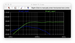
This looks fairly close to the MJK prediction, although the weak port resonance at around 900Hz is missing, giving less HF ripple. The port tuning is also slightly low (40 rather than 45Hz) but that is probably due to the taper approximation.
My original drawing has a folded line section which has a fairly uniform taper from 1.36Sd down to 0.53Sd at the port. To model this, I approximated the taper with a cascade of 7 straight line sections with diminishing cross-sections. The first two had the stuffing density at 100%, the next two at 50%, and the final three at 0%. Fiddling with the global K_fiber parameter until the results looked sensible (K_fiber=500) gave the following plot:

This looks fairly close to the MJK prediction, although the weak port resonance at around 900Hz is missing, giving less HF ripple. The port tuning is also slightly low (40 rather than 45Hz) but that is probably due to the taper approximation.
Last edited:
But what is the density assumed?
The MJK worksheets assume a maximum density of 1lb/cu.ft.
The default parameters assume a density of 16 kg/m3 which is the value I found for the non-pressed dacron
Firstly, the MJK software is widely regarded as the gold standard for loudspeaker cabinet modelling. Literally thousands of speakers, including commercial designs have used it, because the measured performance agrees very closely to the simulation. Its only real limitation is that only dacron damping is supported.
Regarding my example, the parameters used are fairly standard. Making the chamber smaller makes the performance worse, because the line section then becomes longer (for a given total volume) so the taper has to be reduced as well to keep the line 'on tune'. But a lower taper gives poorer ripple suppression. This is why most people end up with tapers in the range 5:1 to 10:1 or even higher.
The driver offset is determined by the driver dimensions (incl tweeter) so that cannot really be increased, unless you want a really ugly looking speaker!
You will see that the predicted ripple from the MJK software is about 1dB peak to peak, including the first dip. But the first dip in the foam version is clearly much worse. That 'wierd flat dip' never happens using fibre stuffing.
I completely agree with you about MJK software, I am indeed convinced that it has no limitation regarding fiber-damped TLs in general. The limitation only exists if you intend to simulate a foam-damped TL: in this case it is necessary to take into account the cross-section area of the pipe not occupied by the damping material and the big difference in the speed of sound between air and foam.
I was thinking about a completely different design, like a full tapered TL without a coupling chamber and a longer offset.
Regarding the flat deep you only need to increas the damping material if you want to reach a result similar to fiber. Foam is a good material, but it is not magic 🙂
There seems to be a bug in the straight fibre model.
Setting the filling rate to 0 or 100 causes the plots to display as ~ -300dB. Setting it to 0.1 or 99.9 is OK.
Thanks for the report, I need to insert some infinitesimals, as I did for the other blocks, to prevent SpicyTL from assigning the value 0 to some components.
OK, some results using the straight fibre line SpicyTL model:
My original drawing has a folded line section which has a fairly uniform taper from 1.36Sd down to 0.53Sd at the port. To model this, I approximated the taper with a cascade of 7 straight line sections with diminishing cross-sections. The first two had the stuffing density at 100%, the next two at 50%, and the final three at 0%. Fiddling with the global K_fiber parameter until the results looked sensible (K_fiber=500) gave the following plot:
View attachment 924563
This looks fairly close to the MJK prediction, although the weak port resonance at around 900Hz is missing, giving less HF ripple. The port tuning is also slightly low (40 rather than 45Hz) but that is probably due to the taper approximation.
To make the simulation more similar to that of MJK's model you must always consider the TL to be 100% filled (99.9) and work only on the k_fiber parameter. The default value is 16 kg/m3 which is equivalent to a 100% fill with non-pressed dacron. In this way the simulation will consider only the damped line, exactly as it does the model of MJK
To make the simulation more similar to that of MJK's model you must always consider the TL to be 100% filled (99.9) and work only on the k_fiber parameter. The default value is 16 kg/m3 which is equivalent to a 100% fill with non-pressed dacron. In this way the simulation will consider only the damped line, exactly as it does the model of MJK
OK thanks, that probably explains the small differences.
Firstly, the MJK software is widely regarded as the gold standard for loudspeaker cabinet modelling. Literally thousands of speakers, including commercial designs have used it, because the measured performance agrees very closely to the simulation. Its only real limitation is that only dacron damping is supported.
Indeed. I have drawn hundreds of those bite for Scott and others. Rarely doe the build not come close to the model. Having someone that knows what they are doing really helps too.
The lack of an adequate damping material library means that one cannot explore some designs, like aperiofic TLs. Then one has to start adding experience to the design.
dave
The MJK worksheets assume a maximum density of 1lb/cu.ft.
16 kg/m3
16 kg/m3 = 0.998847 its/in2
A higher density than in any of the lines i have drawn IIRC.
in this case it is necessary to take into account the cross-section area of the pipe not occupied by the damping material and the big difference in the speed of sound between air and foam.
One has to ask the question why the foam effectively eats line volume, and why is the speed of sound changed. That has been a red herring in the past.
dave
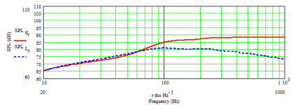
I thought I would try and get a better handle on the difference between foam and fibre using a simple test line, so I set up a 1m long line in the MJK software, fully filled with fibre at 1lb/cu.ft.
The driver is the MW16P-8 with 1W input power (giving 88dB at 1m) and the line cross-section is 119cm^2 (=Sd). Driver offset is zero.
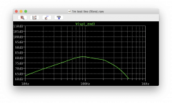
I then set up the same model in SpicyTL and adjusted the K_fiber parameter such that the low frequency port level was the same as the MJK model (81dB). K_fiber needed to be set to 500. Finally, the foam line was used, with the fill factor set to 100%.
Here's the MJK output (the dashed blue line is the port output):
Here's the SpicyTL fibre line output:
Here's the SpicyTL foam line output:
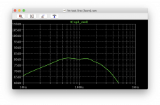
It can be seen that the foam line gives the same low frequency level as the fibre, but the SpicyTL model rolls-off far more than it should with both materials.
The driver is the MW16P-8 with 1W input power (giving 88dB at 1m) and the line cross-section is 119cm^2 (=Sd). Driver offset is zero.
I then set up the same model in SpicyTL and adjusted the K_fiber parameter such that the low frequency port level was the same as the MJK model (81dB). K_fiber needed to be set to 500. Finally, the foam line was used, with the fill factor set to 100%.
Here's the MJK output (the dashed blue line is the port output):

Here's the SpicyTL fibre line output:

Here's the SpicyTL foam line output:

It can be seen that the foam line gives the same low frequency level as the fibre, but the SpicyTL model rolls-off far more than it should with both materials.
On edit:
There was an error in the foam line parameters, now corrected:
View attachment 924909
Low frequency level for the foam line about 3dB lower than the fibre, but both still showing more roll-off than MJK.
What happens to the port output if you set k_fiber to 250?
500 is definitely too high, and that is what determines the steep roll off.
That has been a red herring in the past.
Interesting, I would like to read something on this subject. Can you give me some references?
Here is a link to a paper titled "Analysis of Damping Materials in a Transmission Line Loudspeaker System." It was presented at the New Trends in Audio and Video conference held in Poland in 2012.
http://www.eletel.p.lodz.pl/docs/aktualnosci/Lusztak_Krzysztof.pdf
It's a pretty quick read, and you will all draw your own conclusions from its results, but let me just say that the paper's authors also found that acoustic foam significantly slows down the wave velocity in the tube.
http://www.eletel.p.lodz.pl/docs/aktualnosci/Lusztak_Krzysztof.pdf
It's a pretty quick read, and you will all draw your own conclusions from its results, but let me just say that the paper's authors also found that acoustic foam significantly slows down the wave velocity in the tube.
I would like to read something on this subject. Can you give me some references?
MJK. Augspurger. Others.
dave
MJK. Augspurger. Others.
dave
Could you be more specific? I don't know of any work by MJK or Augspurger about foam.
What happens to the port output if you set k_fiber to 250?
500 is definitely too high, and that is what determines the steep roll off.
Here you go:
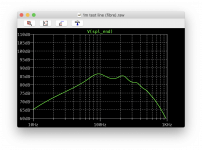
Response shape and level now drastically different to the MJK model, but steep roll-off largely still there. I had to increase K_fiber to 500 to get the response of my original TL design close to the MJK prediction too. It suggests your fibre model isn't correct.
Here is a link to a paper titled "Analysis of Damping Materials in a Transmission Line Loudspeaker System." It was presented at the New Trends in Audio and Video conference held in Poland in 2012.
http://www.eletel.p.lodz.pl/docs/aktualnosci/Lusztak_Krzysztof.pdf
It's a pretty quick read, and you will all draw your own conclusions from its results, but let me just say that the paper's authors also found that acoustic foam significantly slows down the wave velocity in the tube.
Foam is able to significantly slow down the wave velocity
in the tunnel, so it is possible to virtually lengthen the
tunnel. This may be utilized to physically reduce the size of
the enclosures.
Many thanks dkjosness, I did not know this publication. That's exactly what I've observed as well.
I have read other papers dedicated to poroelastic materials that talk about slowing down in the speed of sound perfectly in line with what I have experienced.
- Home
- Loudspeakers
- Subwoofers
- SpicyTL - Transmission Line Simulation Model
