Just to clear up mu previous post where I wrote the word "tube" - with quotes (straight "tube"). Actually, I was recommending a straight, long rectangular shape test enclosure - i.e. straight "tube". Of course rectangular shape enclosure is much better for TL testing than real tube (without quotes)....I also experimented with a TL of circular shape and c/s much larger than Sd, just to verify that both gave reliable results and that the rectangular shape did not create alterations in the response. Once I verified this, I returned to the rectangular shape, which is much more practical for foam simulations. The rectangular shape was also essential for me to model the effect of the offset on the response...
Keep up the good work!
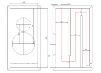
How big(area in crossection) is your line? I run rs100-8 in offset 42/80cm entries to 3” sched 40 pipes(45.6cm2) at 122cm total. I give up few cm on the end offsetting the exit a bit upstream.. These are fully stuffed, however that is very very open and teased. Another version (pic) i played around with for fun was an Mtm is two seperate 3” pipes that converge as a single and exit with the short stub at the end. Same length essentially but with some bends and bringing the exit closer to the drivers.
Just wondering if you prefer a size?
Here you can see a design I made last year with the RS100-4. The c/s area was near 50cm2.
Hado English – Transmission Line Speakers
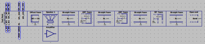
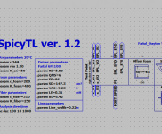
I think you can simulate your set-up with SpicyTL. Acoustically it should work as in the figure.
Attachments
How does this compare to what Hornresp does for modelling damping material?
I'm sorry but I can't tell you how Hornresp models the damping material inside the TL.
Andrea, Thanks for sharing this. There has been some chatter between folks curious about using two speakers in a TL. I think much of it started in the thread "An improved Transmission Line alignment". It mainly boils down to this: Is it better to place the speakers at the 1/4 point as close together as possible or to place them at 1/3 and 1/5 the line length in an attempt to cancel out the first two odd harmonics" (Not sure if the terminology is right)
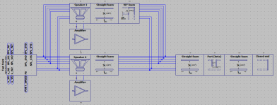
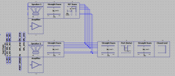
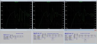
Your model allows playing around and investigating this question. I am showing 3 models here, one speaker at 1/4 length, two speakers tight and centered on 1/4 length, two speakers at 1/3 and 1/5 length.
The two speaker models are powered at 1.415V and the single is at 2.83V. Everything else is the same between them. Foam depth was picked to easily see the changes but filter out the worst "noise". Speakers are RS225, line length is 300CM, line area is 230CM^2.
My observations. The single speaker at 1/4 placement does really well at the low end and is 5db over the other two at 30HZ. Otherwise the single speaker response is rougher than the other two models. The dual 1/4 placement and the 1/3 1/5 placement speakers are very similar and while the 1/3 1/5 is consistently better it might make sense for building ease and proximity of the two speakers to just place them close at the 1/4 point.
Attachments
There has been some chatter between folks curious about using two speakers in a TL
There has been talk about composite (ie multiple drivers) in a TL for decades.
The average driver position should be at Zd, and for maximum line excitation as close as you can get them.
Zd it is rarely at an even fraction except under specific conditions (ie in a Met it is usually ½), the optimum depends on the taper, and ideally placement is the result of looking at what the sim spits out.
dave
There has been talk about composite (ie multiple drivers) in a TL for decades.
Yes. I have seen dual drivers in commercial TLs from a while ago. I wanted to play with the location and see if there was some advantage to be had. I have not seen much on this except for a few patents by Bose that came up in the referenced thread.
The average driver position should be at Zd, and for maximum line excitation as close as you can get them.
Zd it is rarely at an even fraction except under specific conditions (ie in a Met it is usually ½), the optimum depends on the taper, and ideally placement is the result of looking at what the sim spits out.
I wasn't interested in modeling an ideal speaker. I was interested in how adjusting placement could possibly improve things using two drivers. I thought the best way to do this was to just give it a try with the simplest system possible to minimize variables.
BTW, the speaker placement at 1/3 and 1/5 was also discussed on Martin's FB page and he was not sure what effect the different placing would have. So I think that certainty on the "correct" way to place two drivers in a TL might lead one down the wrong path.
Andrea, Thanks for sharing this. There has been some chatter between folks curious about using two speakers in a TL. I think much of it started in the thread "An improved Transmission Line alignment". It mainly boils down to this: Is it better to place the speakers at the 1/4 point as close together as possible or to place them at 1/3 and 1/5 the line length in an attempt to cancel out the first two odd harmonics" (Not sure if the terminology is right)
Your model allows playing around and investigating this question. I am showing 3 models here, one speaker at 1/4 length, two speakers tight and centered on 1/4 length, two speakers at 1/3 and 1/5 length.
The two speaker models are powered at 1.415V and the single is at 2.83V. Everything else is the same between them. Foam depth was picked to easily see the changes but filter out the worst "noise". Speakers are RS225, line length is 300CM, line area is 230CM^2.
My observations. The single speaker at 1/4 placement does really well at the low end and is 5db over the other two at 30HZ. Otherwise the single speaker response is rougher than the other two models. The dual 1/4 placement and the 1/3 1/5 placement speakers are very similar and while the 1/3 1/5 is consistently better it might make sense for building ease and proximity of the two speakers to just place them close at the 1/4 point.
Thank you,
SpicyTL is prepared to simulate up to 4 speakers (potentially even different from each other) in the same project. I will include the other two as soon as possible.
Andrea, two questions
I do not see QT or Qe as parameters for the Spk, I suppose that the program calculates those from other parameters present?
LE is at 1Khz or at 10Khz?
Thanks again
The Q is calculated from the other parameters entered.
You must use the Le at 1 KHz.
Hi Andrea
can SpicyTL approximate a "Karlson-type" enclosure ?
Best wishes,
Freddy
Hi Freddy
No I'm sorry, but I don't exclude that I can work on it in the future.
Andrea
Thanks a lot, now everything is clear.The Q is calculated from the other parameters entered.
You must use the Le at 1 KHz.
SpicyTL 1.4
The latest version of SpicyTL is now available for download.
Now you can more accurately model the opening response and adapt it to the type of material used by means of two parameters.
The first parameter is defined as the density of the damping material in kg/m3 and this makes it more intuitive to use. The second parameter (K_1 for foam and K_2 for fiber) defines the HF roll-off
In the graphs you can see the effect of the two parameters separately and their combined effect (DENS 25, 30, 35 kg/m3 and K_1 200, 300, 400).
Andrea
Attachments
- Home
- Loudspeakers
- Subwoofers
- SpicyTL - Transmission Line Simulation Model