Lee,I'm cornfused, what does OP refer to?
OP refers to the "Original Post" by jimmosher (Jim).
Last edited:
Hello Jim,
Great path analysis of the Klipschorn bass horn. I did a far simpler path length/area study of one of my Klipschorns a few years ago. Will have to dig it out for comparison.
I noticed that on the 2D drawing & Table that position 22 shows a height of 19.19" and a width of 8.19" for a total mouth area of 157.16 in.^2.
I think those numbers are in error. At position 22, my Klipschorn measures 12" x 38" for a mouth area of 456 in.^2.
Regards,
Lee
Hi Arkytype,
Apparently the drawing that I got off the web may not be correct in some of it's dimensions. I used all the dimensions I had available to create a 3D model, cut the model to 1/4 of it's size, then unfold the acoustic path, which is the information that you are referring to.
Thanks for the catch.
")
Jim.
Horn with High Initial Flare - I and II
Hi,
Horns with high initial flare rates are again looked at. Dave McBean mentioned that this type of throat is known as a rubber neck.
Both Klipsch horns, the K-horn and Jubilee both make use of horns with high initial flare rates, so there must be something to the technique.
This is an attempt to understand more fully, what is going on.
Jim.
Attachments
Klipsch Design of Experiments
Hi,
This is an old file, and it was one of the first studies I did to accomplish two things:
1) Understand the details of horn design and the effect of driver parameters.
2) Get a better understanding of how Hornresp parameters affect SPL levels.
Jim.
Hi,
This is an old file, and it was one of the first studies I did to accomplish two things:
1) Understand the details of horn design and the effect of driver parameters.
2) Get a better understanding of how Hornresp parameters affect SPL levels.
Jim.
Attachments
Dave McBean mentioned that this type of throat is known as a rubber neck.
Just to clarify, I mentioned that the initial rapid flare is known as a rubber throat (not a rubber neck).
The term was originally coined by Paul Klipsch.
Hello Jim, et al,
Klipsch forum member "formica" posted some fairly accurate (German?) Klipschorn drawings back in 2003. All dimensions are metric; so 3/4" material is shown as 19 mm instead of the correct 19.05 mm. 1/2" material is shown as 13 mm, not the correct 12.7 mm. also, the horn throat differs slightly from the 3" x 13" in my Klipschorn. Other dimensions appear to match my loudspeaker.
Speaker Plans - Technical/Modifications - The Klipsch Audio Community
Lee
Just to clarify, I mentioned that the initial rapid flare is known as a rubber throat (not a rubber neck).
The term was originally coined by Paul Klipsch.
Hi David,
My best option is drop using the rubber throat reference, so that I do not continue to repeat this mistake. From now on I will stick with "high initial flare", which makes more sense to me anyways.
Jim.
Hello Jim, et al, ....
Lee
Here is the reference I used for cabinet dimensions...
It's actually a very clean rendering of an original drawing, and I can not verify how accurately it was created regarding your speaker cabinet dimensions.
Jim.
Attachments
Last edited:
From now on I will stick with "high initial flare", which makes more sense to me anyways.
FWIW, I like Altec's 'one size fits all' throat adapter whether a separate part or built in, which could be a constant or conical taper depending on the needs of the app.
GM
Just wanted to say this is a very cool thread, about a still very cool product. I'm curious-since the horn impedances I measured were always spiky and messy* and therefore passive crossovers not able to work really as they ought, is anyone running digital time-aligned crossovers on these?
Optimum Horn Shape and Possible Driver
Hi,
This is a good time to post the last three PDFs regarding optimum horn shape and possible driver for best response.
It turns out that a corner horn with a high initial flare gives an advantage over a pure exponential flare. You will have to read the PDF to find out how and why.
________
Picking a few driver candidates turned out to be harder than at first thought, and things could change in the future after more in depth looking. For now however, it seems that two drivers with similar attributes give almost exactly the same simulated acoustic response.
The "candidate" PDF also makes use of Don Keele's early paper regarding T/S parameters and their use in horns.
The "summary" PDF gives an overview of the findings thus far. This is where I will pick up again this fall.
________
This will be the last installment in this thread for some time, since warmer weather is upon us and there are now things to do outside around the house. I hope you enjoyed the research thus far.
Jim.
Attachments
Last edited:
Just wanted to say this is a very cool thread, about a still very cool product. I'm curious-since the horn impedances I measured were always spiky and messy* and therefore passive crossovers not able to work really as they ought, is anyone running digital time-aligned crossovers on these?
Hi,
At some point in the future, I plan on using a digital delay on the high end driver(s), to get better time alignment between the drivers.
Years ago, I had another custom bass horn cabinet and used a digital delay. It was a lower cost unit and muddled the high end however, to the point where I removed it from the system.
Jim.

@jimmosher - pretty cool ! - do you envision the new optimized horn as relatively easy to build ?
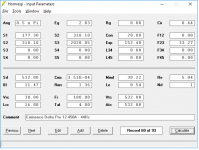
hope I simmed it right....
Hi freddi,
Something looks off in your sim. The final flare should be exponential. The length at 152.4 should have EXP next to it. You can double click on EXP to change to that setting.
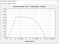
Also, since there are two 12 inch woofers, the simulation needs to include this as well. Note that the sim below shows that two woofers have been selected and are connected in parallel.
Regarding the complexity of the build, I would think that this build would be more labor intensive than a typical K-horn cabinet, as I intent to produce somewhat rounded corners in the bends inside the cabinet. This will need to be researched and/or modeled before proceeding with any kind of build.
Just curious; why did you simulate a 2pi space? A corner horn would always be mounted in a 0.5pi environment, as this makes the use of a bass horn feasible in homes, size wise.
Jim.
Attachments
Last edited:
it was late - so missed the EXP part. Regarding 2 pi just curious as have been looking at the old "Dean cornerless cornerhorn".
so the finished speaker could be something like the Jubilee - what's the easiest way in hornresp to get both halves simulated?
Hi,
To sim two 12 inch speakers, display the SPL curve data
Click on Tools | Multiple Speakers.
Then select Parallel and number of speakers, in this case two.
The SPL graph will be rerendered with the updated speaker setup.
The setup information will be displayed at the top of the SPL graph.
Jim.
You could also configure the driver setting for two drivers and simply double the areas. That way you could still simulate multiple speakers for the full, double-driver cornerhorn. Assuming one would have two for a stereo pair in a normal sized living room. At lower frequencies, the wavelengths are so long that the horns will behave as though they are stacked. I don't often look at that, because the effect is pretty insignificant compared to my roomgain, but it might be significant enough for this type of impressive project.
Bruce Edgar did work on optimal reflectors for bass horns, his finding was that 45 degree reflectors are better than curved reflectors. Have you seen his articles about the Showhorn and the Monolith? I think we can do more in the same volume, or have the same response in a smaller box with all the simulation tools and driver specs at our disposal online, but his fundamental insight about what works and what not is still rock solid.
Bruce Edgar did work on optimal reflectors for bass horns, his finding was that 45 degree reflectors are better than curved reflectors. Have you seen his articles about the Showhorn and the Monolith? I think we can do more in the same volume, or have the same response in a smaller box with all the simulation tools and driver specs at our disposal online, but his fundamental insight about what works and what not is still rock solid.
- Status
- This old topic is closed. If you want to reopen this topic, contact a moderator using the "Report Post" button.
- Home
- Loudspeakers
- Subwoofers
- Klipsch Bass Horn Acoustic Analysis