Horn Bends
In regards to the bending and bifurcating horn pathways, see
Title: Modal sound propagation in curved horns
of rectangular cross-section
Author: Bjørn Kolbrek
Thesis: Master of Science in Electronics
Date: June 2013
Bjørn posts frequently here, so ask him for a copy.
In the meantime, the following article may be helpful. Even though this article addresses bends in musical instrument bores, the physics of the matter remain materially unchanged for loudspeaker horns of rectangular section as well.
WHG
>snip<
Regarding the complexity of the build, I would think that this build would be more labor intensive than a typical K-horn cabinet, as I intent to produce somewhat rounded corners in the bends inside the cabinet. This will need to be researched and/or modeled before proceeding with any kind of build.
>snip<
Jim.
In regards to the bending and bifurcating horn pathways, see
Title: Modal sound propagation in curved horns
of rectangular cross-section
Author: Bjørn Kolbrek
Thesis: Master of Science in Electronics
Date: June 2013
Bjørn posts frequently here, so ask him for a copy.
In the meantime, the following article may be helpful. Even though this article addresses bends in musical instrument bores, the physics of the matter remain materially unchanged for loudspeaker horns of rectangular section as well.
WHG
Attachments
Last edited:
Hi Bill - would some room corner extension past what a sim may indicate also apply to University Sound's "Dean - Cornerless Corner Horn" ?
Best Wishes,
Fred
https://i.imgur.com/KxArg5V.png
Best Wishes,
Fred
https://i.imgur.com/KxArg5V.png
Too-Small
Hi Fred,
The driver is quickly unloaded below 60 Hz. Some benefit may be expected by corner placement. In any event, to reproduce the bottom two octaves will require you to deploy sub-woofers. This is a good example of why bass horns should be designed to work out of room corners. After all these years, the EV Pat IV still remains my favorite commercial bass horn. I have yet to hear something superior during this time (circa 1050s).
Regards,
Bill
Hi Bill - would some room corner extension past what a sim may indicate also apply to University Sound's "Dean - Cornerless Corner Horn" ?
Best Wishes,
Fred
https://i.imgur.com/KxArg5V.png
Hi Fred,
The driver is quickly unloaded below 60 Hz. Some benefit may be expected by corner placement. In any event, to reproduce the bottom two octaves will require you to deploy sub-woofers. This is a good example of why bass horns should be designed to work out of room corners. After all these years, the EV Pat IV still remains my favorite commercial bass horn. I have yet to hear something superior during this time (circa 1050s).
Regards,
Bill
After all these years, the EV Pat IV still remains my favorite commercial bass horn. I have yet to hear something superior during this time (circa 1050s).
... Bill
It's also my experience (since 1968) ... in home made .
Chapeau bas for your info-support ...
Regards.
Karel
It's also my experience (since 1968) ... in home made .
Chapeau bas for your info-support ...
Regards.
Karel
Merci beaucoup.
Bill
Hello everyone, here is a nice corner horn inspired by the Klipschorn.
Cialtronic: The Little Big Horn
Could anyone try to simulate it? I have no idea how to do it. It is supposed to be better than the Klipschorn, at least this is the story that the designer (now in his sixties) keeps telling.
The use of those drivers was forced by Audax, the one who sponsored the kit.
Hi Jim,
Look upon the K-Horn as the 'throat' of a much larger horn formed by the adjoining room walls. Here, room size rules. Some novel non-Klipsch designs are attached.
Regards,
Bill
Thanks Bill for the DCH paper. That design is very creative.
Regarding the walls becoming part of the horn, yes, I follow that concept, and that is what is meant by 0.5 pi.
Jim.
Hello everyone, here is a nice corner horn inspired by the Klipschorn.
Cialtronic: The Little Big Horn
Could anyone try to simulate it? I have no idea how to do it. It is supposed to be better than the Klipschorn, at least this is the story that the designer (now in his sixties) keeps telling.
The use of those drivers was forced by Audax, the one who sponsored the kit.
Hi,
I just looked at the plans for this design, and the mouth size seems much smaller than the K-horn, which to me, does not seem like a good idea. I think the K-horn mouth size is already on the small side to get to 40 Hz reasonably.
Just my opinion.
Jim.
In regards to the bending and bifurcating horn pathways, see
Title: Modal sound propagation in curved horns
of rectangular cross-section
Author: Bjørn Kolbrek
Thesis: Master of Science in Electronics
Date: June 2013
Bjørn posts frequently here, so ask him for a copy.
In the meantime, the following article may be helpful. Even though this article addresses bends in musical instrument bores, the physics of the matter remain materially unchanged for loudspeaker horns of rectangular section as well.
WHG
Hi Bill,
Thanks for the papers again!
I wrote a message to Bjorn, making a request for his paper.
Regarding the EV Pat, it looks very similar to the Klipschorn, at least from my short viewing, especially the bass cabinet. What is it about this speaker that you recommend it so highly?
Thanks, Jim.
Last edited:
Pat IV Details
Hi Bill,
Thanks for the papers again!
I wrote a message to Bjorn, making a request for his paper.
Regarding the EV Pat, it looks very similar to the Klipschorn, at least from my short viewing, especially the bass cabinet. What is it about this speaker that you recommend it so highly?
Thanks, Jim.[/QUOTE
Hi
The Patrician IV is a particular licensed version of the Klipsch Corner Horn, details of which were engineered by Roy Carlson (Cabinet) and Louis Hoodwin (Drivers & Crossovers) of ElectroVoice. Duplicating this system, particularly, the mid-bass region (200-600 Hz range), would be a challenge. The only viable driver alternatives are a Community Light & Sound M4 (2), or a JBL CMCD (1) unit. For optimal results, a larger horn should be used as well. Something like Roy Delgado's Modified Tractrix (Jubilee) would be a good option. Tom Danley's Unity Horn is another attractive option as well, were the mid-bass could be handled by four. small open frame drivers. For the top end, there are numerous alternatives, with the beryllium drivers from TAD, JBL and others at the top of the list.
Regards,
Bill
Attachments
The Patrician IV .....
Duplicating this system, particularly, the mid-bass region (200-600 Hz range), would be a challenge.
For optimal results, a larger horn should be used as well.
Regards,
Bill
Hi.
FYI
indeed.
I opted for (old school) the DIY solution WE66A (& JBL2482), Range 300Hz (even a little lower) to 1200kHz, max 2 octaves LR 24dB / oct & actif X-over.
It's music, I like it.
Karel
Here's a link to Bjorn's paper.
Modal sound propagation in curved horns of rectangular cross-section
Lee
Modal sound propagation in curved horns of rectangular cross-section
Lee
Too-Low C/O Frequency Issue
I like the this phenolic diaphragm compression driver as well; but at 200 Hz c/o point, it will unnecessarily limit the dynamic range of the entire system. The alternatives already provided are superior as they do not impose this limitation.
With some careful design and a patent test and rework regime, a walk up of the c/o to say 400 Hz. should be possible. In this setting I would also consider using the BMS 4599ND [1]; and like EV, I would use them in pairs. WHG
Hi.
FYI
indeed.
I opted for (old school) the DIY solution WE66A (& JBL2482), Range 300Hz (even a little lower) to 1200kHz, max 2 octaves LR 24dB / oct & actif X-over.
It's music, I like it.
Karel
I like the this phenolic diaphragm compression driver as well; but at 200 Hz c/o point, it will unnecessarily limit the dynamic range of the entire system. The alternatives already provided are superior as they do not impose this limitation.
With some careful design and a patent test and rework regime, a walk up of the c/o to say 400 Hz. should be possible. In this setting I would also consider using the BMS 4599ND [1]; and like EV, I would use them in pairs. WHG
Attachments
Klipschorn throat location quiz
In keeping with Jim's thread title, Klipsch Bass Horn Acoustic Analysis, I submit a couple of drawings of the innards of my 1976 Klipchorns and also pose a question as to the location of the Klipschorn's throat(s)..
What I'd like to know is which (if any) of the "throat" locations I've identified is the actual & verifiable Klipschorn throat? Be prepared to argue your selection!
The literature (papers, books, articles) seems to gloss over the throat location issue when it comes to bifurcated acoustic paths. The K-33E outfitted as a compression driver is feeding two horns of equal length. It seems to me the classic exponential horn equations are (like speed limit signs) only a suggestion to the experimenter as how to go about designing and building a bifurcated/folded horn.
While it's true you only pick one of the two paths to model/measure, when it comes to mouth area, some (including PWK) count both mouth areas in their design explanation, not just one as I think it should be.
So, which labeled throat do you say is the correct one(s) to choose?
Admittedly, T1 & T2 are real close with each having an area of 12.5" x 13", not the more cited 3" x 13"; (Don't forget the 1/2" vertical partition splitting the 3" x 13" opening.)
T3 is a somewhat logical choice (at 1.5" x 12.5") as it is at the confluence of the two horn paths and the splitter acts as the first area expansion.
T4a & T4b as well as T5a & T5b could be considered as well.
The attachments are full scale and drawn as a vertical section thru the motor board to the front panel. Again, the measurements are of my Klipschorn. Splitter sizes and woofer slots have varied over the years.
Lee
Attachments
Premature Choice
Two possible explanations come to mind for throat variances addressed here and they are not necessarily mutual exclusive nor do they lead to making an immediate choice regarding superiority of a particular configuration:
1) Over the production life of this enclosure, which has certainly been protracted, I am sure the parameters of the driver used have undergone changes that have required modification of horn acoustics that are easily implemented by alteration of throat dimensions. Thus, to make the right choice requires specification of a particular set of driver parameters and their tolerances only known to the folks at Klipsch.
2) These minor differences may also be due to individual voicing of each unit before final assembly, base on measured driver parameters of the specific unit to be married to a standard horn body by using different throat sub-assemblies to achieve a superior match.
WHG
In keeping with Jim's thread title, Klipsch Bass Horn Acoustic Analysis, I submit a couple of drawings of the innards of my 1976 Klipchorns and also pose a question as to the location of the Klipschorn's throat(s)..
What I'd like to know is which (if any) of the "throat" locations I've identified is the actual & verifiable Klipschorn throat? Be prepared to argue your selection!
The literature (papers, books, articles) seems to gloss over the throat location issue when it comes to bifurcated acoustic paths. The K-33E outfitted as a compression driver is feeding two horns of equal length. It seems to me the classic exponential horn equations are (like speed limit signs) only a suggestion to the experimenter as how to go about designing and building a bifurcated/folded horn.
While it's true you only pick one of the two paths to model/measure, when it comes to mouth area, some (including PWK) count both mouth areas in their design explanation, not just one as I think it should be.
So, which labeled throat do you say is the correct one(s) to choose?
Admittedly, T1 & T2 are real close with each having an area of 12.5" x 13", not the more cited 3" x 13"; (Don't forget the 1/2" vertical partition splitting the 3" x 13" opening.)
T3 is a somewhat logical choice (at 1.5" x 12.5") as it is at the confluence of the two horn paths and the splitter acts as the first area expansion.
T4a & T4b as well as T5a & T5b could be considered as well.
The attachments are full scale and drawn as a vertical section thru the motor board to the front panel. Again, the measurements are of my Klipschorn. Splitter sizes and woofer slots have varied over the years.
Lee
Two possible explanations come to mind for throat variances addressed here and they are not necessarily mutual exclusive nor do they lead to making an immediate choice regarding superiority of a particular configuration:
1) Over the production life of this enclosure, which has certainly been protracted, I am sure the parameters of the driver used have undergone changes that have required modification of horn acoustics that are easily implemented by alteration of throat dimensions. Thus, to make the right choice requires specification of a particular set of driver parameters and their tolerances only known to the folks at Klipsch.
2) These minor differences may also be due to individual voicing of each unit before final assembly, base on measured driver parameters of the specific unit to be married to a standard horn body by using different throat sub-assemblies to achieve a superior match.
WHG
.......While it's true you only pick one of the two paths to model/measure, when it comes to mouth area, some (including PWK) count both mouth areas in their design explanation, not just one as I think it should be.
So, which labeled throat do you say is the correct one(s) to choose?.....
Lee
Hi Lee,
I agree with you, since the K-horn is split in two halves, that the throat size should really be split in half when modeling the shape.
When I modeled the twin (12) drivers, I split the throat into 1/4 of it's full size.
Right now I favor a "phasing plug" for each 12 inch driver and the acoustic paths will be separated physically. The intent of this will hopefully keep the phasing mismatches smaller when the acoustic signal moves from the cone to the horn path.
Jim.
Last edited:
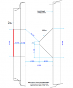
What I'd like to know is which (if any) of the "throat" locations I've identified is the actual & verifiable Klipschorn throat?
The throat is as shown by the red line in the attachment. Behind it is the throat chamber, and in front of it are the horn segments, the first of which is cylindrical (being the port tube opening through the motor board and half-inch thick panel).
Attachments
I agree with you, since the K-horn is split in two halves, that the throat size should really be split in half when modeling the shape.
When I modeled the twin (12) drivers, I split the throat into 1/4 of it's full size.
Hi Jim,
A Klipschorn bass corner horn should be modelled in Hornresp full-size. If only one half of the system is considered, the driver parameter values need to be altered and the solid radiation angle specified as 0.25 x Pi steradians (sixteenth space) to obtain the correct results. Even if adjusted driver parameter values can be determined, the required Ang value is not supported by the program.
Kind regards,
David
It is one thing, one horn design. Why split it? I understand there are two pathways along which the sound waves travel, but they originate with the same driver, they exit fairly close together. The separate waves recombine at lower frequencies, the pathlength difference causes comb filtering at higher frequencies. Other than that, it's a single horn.
I don't have a reference to a paper ready, but remember reading at least a reference to a paper that concluded splitting a horn into multiple equivalent pathways is irrelevant for basic horn function.
I know a friend noticed subjective dynamic losses when he split a horn in four or more pathways. I think he concluded that the relative amount of horn wall was increased, causing more friction losses. But that wasn't a scientific conclusion.
- Status
- Not open for further replies.
- Home
- Loudspeakers
- Subwoofers
- Klipsch Bass Horn Acoustic Analysis